IJEDR1504013
International Journal of Engineering Development and Research (www.ijedr.org)1
A Novel Approach to Reactive Power Control Using
Plant Growth Simulation Algorithm
Tarun Gupta, Neha
Department of Electrical Engineering Shri Sai College of engineering and technology
_______________________________________________________________________________________________________
Abstract— Reactive power control has been an important problem for the last many years. The role of reactive power can be understood as it affects voltage stability, power factor and losses in a power system. To solve this problem many approaches have been used in the literature. Capacitors are utilized for the same. But the problem lies in finding the optimal location and size of the capacitors. This thesis proposes a novel idea of using Plant Growth Simulation Algorithm for finding the optimal placement of capacitors and size of the capacitors deployed.
_______________________________________________________________________________________________________ I.INTRODUCTION
Power Compensation: During the past 20 years, the rise in current demand has conferred higher needs from the facility business. A lot of power plants, substations, and transmission lines got to be created. However, the foremost [4] ordinarily used devices in gift power system square measure the mechanically-controlled circuit breakers. The long change periods and distinct operation create them tough to handle the overtimes modified masses swimmingly and damp out the transient oscillations quickly. So as to compensate these drawbacks, giant operational margins and redundancies square measure maintained to safeguard the system from dynamic variation and live through faults.
II.BASIC PRINCIPAL OF POWER COMPENSATION IN TRANSMISSION:
It shows the simplified model of an influence transmission. 2 power grids square measure [10] connected by a cable that is assumed lossless and painted by the electrical phenomenon XL. 11δ∠V and 22δ∠V represent the voltage phases of the 2 power system buses with angle δ= δ1- δ2 between the 2.
Figure: 1.1. Power transmission system: (a) simplified model; (b) phase diagram [10] The magnitude of this within the cable is given by:
(1) The active and reactive parts of this flow at bus one square measure given by:
(2) III.LITERATURESURVEY
Neelima, S. et al. [15] has described the distribution system is interface between bulk power system and consumers. Among these systems are radial distributions system is well known because of the low cost and design. For purpose, In this, two stage methodologies have been used. In the first stage, load flow of pre-compensated distribution system has been carried out while using dimension reduces distribution load flow algorithm. In second stage, Genetic Algorithm technique has used to define the optimal location and size of capacitors the cost of energy loss and capacitor cost minimum.
IJEDR1504013
International Journal of Engineering Development and Research (www.ijedr.org)2
Sirjani, Reza et al. [17] has discussed the power systems capacitors which are used to transfer reactive power to decrease loss and to increase the voltage profile. The optimal placement of capacitors is important to ensure the system total capacitor costs and power losses are minimal. To decrease shunt capacitors, power loss that are installed in power distribution networks, which are used to compensate for the reactive power.Abul’Wafa Ahmed R. et al. [1]had prescribed an effective and efficient approach for capacitor in radial distribution systems define optimal sizes and locations capacitors with objective reduction of power loss or improve voltage profile. A loss sensitivity method is used to opting candidate locations for capacitor placement. For 28 node feeder has two stage method is proposed: a reconfiguration of feeder in initial stage followed the optimal capacitor allocation consider as a second stage. The two stage method is applicable to 85 node feeder for provided optimum configuration of tie switches.
IV.PROPOSED METHODOLOGY
The problem of load flow in power system forms an example of classic engineering problems in power system. In most of the cases of circuit analyses, the network components are limited to known value of impedances with current and voltage source.
Table 1: Different types of Load Flow Buses
Classification Known Parameter Unknown Parameter
Load Bus or PQ bus P, Q V,
Generator Bus or PV bus P, V Q,
Swing or V,
bus V,
P, QThe set of unknowns producing power balance at all of the specified buses in the system is solved by the load flow algorithm. The power balance equation is given by equation
given given comp comp
i i i i
P
jQ
P
jQ
, (11) Where
*
comp comp
i i i i
P
jQ
V I
. (12)Stated otherwise, the specified power at a particular bus must be same as that of the power flowing into the system. The power which is generated is taken as positive power, which makes it consistent with KCL equation YV=I.
Since two unknowns are present at every bus, the load flow problem is of the size 2N, where N denotes the number of buses. These are obtained from the KCL equations as given below:
* * , 1 N given given comp comp
i i i i i i i i j j
j
P
jQ
P
jQ
V I
V
y V
(13) The above stated equation is then separated into real and imaginary components as shown:
, , 1cos
N giveni k k l l k l k l
k
P
V
y
V
(14)
, , 1sin
N giveni k k l l k l k l
k
Q
V
y
V
(15) Where
V
k
V
k
k,
V
l
V
l
l,
y
k l,
y
k l,
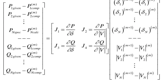
k l, (16) The problem now is to find a set of bus voltages which satisfies these equations stated above. Newton-Raphson MethodIn order to solve the load flow problem, expansion of the Newton-Raphson method is done first. In mixed rectangular-polar form it is expressed as:
1
( ) 1 1
1 1 1
( ) 2 2 2 2 1 ( ) 1 2 ( ) 3 4 1 1 ( ) 2 2 ( ) m m m
given comp m m
m given comp m m N Nspec Ncalc m given comp m given comp m Ngiven Ncomp P P P P P P J J P P V Q Q J J Q Q V Q Q Q Q
1 1 1 1 2 2 1 m N m m m m m m N N V V V V V V IJEDR1504013
International Journal of Engineering Development and Research (www.ijedr.org)3
V
J
J
J
J
Q
P
4 3
2 1
. (17)
The problem dimension can be given as
2
N
PV busses
2
since update ofV
at PV busses are not needed, andV
and
are updated at the slack bus although not necessary.V.RESULTSANDDISCUSSION
This chapter discusses the various simulation results obtained by implementing the proposed algorithm explained in previous chapter for our problem statement. All the simulations have been done MATLAB R 2013b with a 6GB RAM computer with core i5 processor.
Dataset: Three types of datasets have been utilized in this thesis. An IEEE-9 bus, 30-bus and 57-bus system has been utilized and capacitor placement problem is dealt with so that we are able to find the optimal solution in terms of loss minimization and voltage stability.
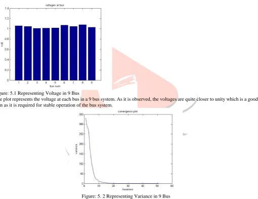
Figure: 5.1 Representing Voltage in 9 Bus
The plot represents the voltage at each bus in a 9 bus system. As it is observed, the voltages are quite closer to unity which is a good sign as it is required for stable operation of the bus system.
Figure: 5. 2 Representing Variance in 9 Bus
IJEDR1504013
International Journal of Engineering Development and Research (www.ijedr.org)4
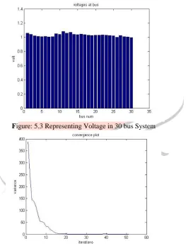
Figure: 5.3 Representing variations in 9 BusFigure 5.3 represents the movement of the morphactin content which starts converging as the iterations are continued. The iterations shows that our proposed algorithm performs quite well.
Figure: 5.3 Representing Voltage in 30 bus System
IJEDR1504013
International Journal of Engineering Development and Research (www.ijedr.org)5
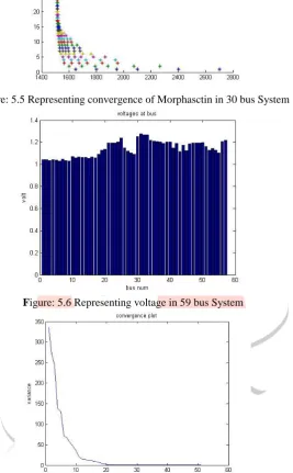
Figure: 5.5 Representing convergence of Morphasctin in 30 bus SystemFigure: 5.6 Representing voltage in 59 bus System
Figure: 5.5 Representing convergence of Morphasctin in 30 bus System
IJEDR1504013
International Journal of Engineering Development and Research (www.ijedr.org)6
Table: Results of All Bus data9-Bus 14 –Bus 30-bus
Bus Number 3,1,9,8 6,2,9,7 2,7,24,24
Selected Size 600, 450, 300, 150 150,300,600,450 300,450,150,600
Loss 3. 3063 3.3075 0.3247
VI.CONCLUSION AND FUTURE SCOPE
A novel idea of Plant Growth Simulation Algorithm has been developed in this thesis to solve the reactive power control problem of the power system. Reactive power is an important parameter in power system which affects many factors such as stability, voltage level, losses etc. To find the optimal location of the capacitor to control the reactive power is a challenging task. To solve this problem a novel approach has been discussed in this thesis.
In future, other algorithms can be tried on the same bus systems. Also the proposed algorithm can be tested on other bus systems. Also hybrid algorithms can be developed to solve the problem. Also STATCOM and SSSC etc can be used to enhance the performance.
VII.REFERENCES
[1] Abul’Wafa, Ahmed R. "Optimal capacitor allocation in radial distribution systems for loss reduction: A two stage method." Electric Power Systems Research 95 (2013): 168-174.
[2] Baran, Mesut E., and Felix F. Wu. "Optimal sizing of capacitors placed on a radial distribution system." Power Delivery, IEEE Transactions on 4.1 (1989): 735-743.
[3] Dehkordi, B. Mirzaeian, et al. "Optimal Capacitor Placement and Sizing in Tabriz Electric Power Distribution System Using Loss Sensitivity Factors and Particle Swarm Optimization (PSO)." International Journal on Technical and Physical Problems of Engineering (IJTPE) 7 (2011): 54-59.
[4] Deng, Yongan. "Reactive Power Compensation of Transmission Lines."Concordia University MASc (2007).
[5] Davoodi, Majid, et al. "Optimal capacitor placement in distribution networks using Genetic Algorithm." Indian Journal of Science and Technology 5.7 (2012): 3054-3058.
[6] Franco, John F., et al. "A mixed-integer LP model for the optimal allocation of voltage regulators and capacitors in radial distribution systems."International Journal of Electrical Power & Energy Systems 48 (2013): 123-130.
[7] Gallego, Ramon A., Alcir J. Monticelli, and Ruben Romero. "Optimal capacitor placement in radial distribution networks" Power Systems, IEEE Transactions on 16.4 (2001): 630-637.
[8] Kannan, S. M., et al. "Optimal capacitor placement and sizing using Fuzzy-DE and Fuzzy-MAPSO methods." Applied Soft Computing 11.8 (2011): 4997-5005.
[9] Kansal, Satish, Vishal Kumar, and Barjeev Tyagi. "Optimal placement of different type of DG sources in distribution networks." International Journal of Electrical Power & Energy Systems 53 (2013): 752-760.
[10] Karayat, Mamta, et al. "Optimal Capacitor and Type-2 DG Placement using Modified KVS–Direct Search Algorithm for Loss Less Distribution."International Journal of Engineering Trends in Electrical and Electronics (IJETEE-ISSN: 2320-9569) Vol 3 (2013): 20-24.
[11] Kodsi, SK Mena, and Claudio A. Canizares. "Modeling and simulation of IEEE 14 bus system with facts controllers." University of Waterloo, Canada, Tech. Rep (2003).
[12] Mahela, Om Prakash, Devendra Mittal, and Lalit Goyal. "Optimal capacitor placement techniques in transmission and distribution networks to reduce line losses and voltage stability enhancement: A review." IOSR Journal of Electrical and Electronics Engineering 3.4 (2012): 01-08.
[13] Mohkami, H., Rahmatollah Hooshmand, and Amin Khodabakhshian. "Fuzzy optimal placement of capacitors in the presence of nonlinear loads in unbalanced distribution networks using BF-PSO algorithm." Applied Soft Computing 11.4 (2011): 3634-3642. [14] Moradi, M. H., and M. Abedini. "A combination of genetic algorithm and particle swarm optimization for optimal DG location and sizing in distribution systems." International Journal of Electrical Power & Energy Systems 34.1 (2012): 66-74.
[15] Nallagalva, Swaroop Kumar, Mukesh Kumar Kirar, and Ganga Agnihotri. "Transient Stability Analysis of the IEEE 9-Bus Electric Power System."International Journal of Scientific Engineering and Technology 1.3 (2012): 161-166.
[16] Sarma, A. Kartikeya, and K. Mahammad Rafi. "Optimal selection of capacitors for radial distribution systems using plant growth simulation algorithm." International Journal of Advanced Science and Technology30.May (2011): 43-54.
[7] Sirjani, Reza, Azah Mohamed, and Hussain Shareef. "Optimal capacitor placement in three-phase distribution systems using improved harmony search algorithm." system 2.18 (2011): 19.