IJEDR1602124
International Journal of Engineering Development and Research (www.ijedr.org)704
Analysis and simulation of voltage sag/ swell of a
distribution system without and with dynamic voltage
restorer (dvr)
1Yogita H. Kataria ,2 Hardik M. Pandya , 3Bharti B. Parmar 1M.E. student, 2 Assistant Professor, 3Assistant Professor
1 (Electrical Engineering Department) 1V.V.P Engineering College, Rajkot, Gujarat India
Abstract - In this technological era, the question of the quality of voltage is rapidly increasing. New technologies are introduced and we are facing many new power quality requirements [18]. Modern industrial devices are mostly based on electronic devices such as programmable logic controllers and electronic control based drives. The electronic devices are very sensitive to disturbances and become less tolerant to power quality problems such as voltage sags, swells and
harmonics. One of these devices is the Dynamic Voltage Restorer (DVR), a modern custom power device used in the most
efficient power distribution networks. In this paper, the usefulness of including DVR in distribution system for the purpose of voltage sag and swell mitigation is described. This paper presents modeling, analysis and simulation of a Dynamic Voltage Restorer (DVR) using MATLAB.
Index Terms -Voltage sag, Voltage swell, Dynamic Voltage Restorer
I INTRODUCTION
Power quality problems are of wide preferable area for the discussion due to the increased use of critical equipments like communication network, process industries etc. [5].
Power Quality problems encompass a wide range of disturbances such as voltage sags/swells, flicker, harmonics distortion, impulse transient and interruptions. Distribution system locates the end of power system and is connected to the customer. So the power quality mainly depends on distribution system. The reason behind this is that the electrical distribution system failure accounts for about 90% of the average customer interruption.
Presently these devices are modified for the use in distribution system so that power quality can be further improved. These modified devices are called Custom Power Devices. The basic Custom power devices which are used for power quality improvement in distribution system are DSTATCOM (Distribution Static Synchronous Compensator), DVR (Dynamic Voltage Restorer), UPQC (Unified Power Quality conditioner) etc. Among these device, Dynamic Voltage Restorer (DVR) belongs to series connected FACTS controllers. The primary function of a DVR is to compensate voltage sags and swells. But it can also perform tasks such as harmonics elimination, reduction of voltage transients and fault current limitation [18].
II.OPERATING PRINCIPLE
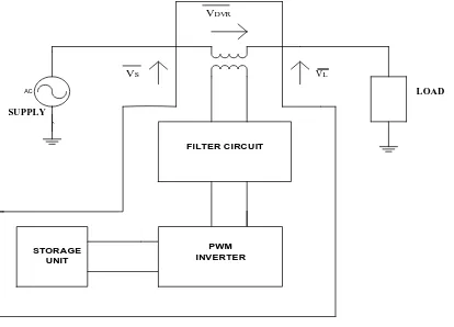
The fundamental principle behind DVR operation is that it injects a voltage waveform through an injection transformer that is the difference between pre-sag and sagged voltage. This is demonstrated in Fig. 1 [17].
IJEDR1602124
International Journal of Engineering Development and Research (www.ijedr.org)705
Fig 1:operation of dvrSeparate control over the magnitude of injected voltage is usually done for a three single phase DVRs.
III
BASIC CONFIGURATION OF DVR`
The general configuration of the DVR as shown in the schematic diagram of DVR as shown in Fig. (2) [17]. Consists of: A Injection/ Booster transformer
B Harmonic filter
C Voltage Source Converter (VSC) D DC charging circuit
E Control and Protection system
A Injection/ Booster transformer
The Injection / Booster transformer is a specially designed transformer that attempts to limit the coupling of noise and transient energy from the primary side to the secondary side. It connects the DVR to the distribution network via the HV-windings and transforms and couples the injected compensating voltages generated by the voltage source converters to the incoming supply voltage. In addition, the Injection / Booster transformer serves the purpose of isolating the load from the system (VSC and control mechanism).
B Harmonic filter
The main task of harmonic filter is to keep the harmonic voltage content generated by the VSC to the permissible level.
C Voltage Source Converter (VSC)
A VSC is a power electronic system consists of a storage device and switching devices, which can generate a sinusoidal voltage at any required frequency, magnitude, and phase angle. In the DVR application, the VSC is used to temporarily replace the supply voltage or to generate the part of the supply voltage which is missing.
There are four main types of switching devices: Metal Oxide Semiconductor Field Effect Transistors (MOSFET), Gate Turn-Off thyristors (GTO), Insulated Gate Bipolar Transistors (IGBT), and Integrated Gate Commutated Thyristors (IGCT). Each type has its own benefits and drawbacks.
The IGCT is a recent compact device with enhanced performance and reliability that allows building VSC with very large power ratings. Because of the highly sophisticated converter design with IGCTs, the DVR can compensate dips which are beyond the capability of the past DVRs using conventional devices.
Figure :2 schematic diagram of dvr D DC charging circuit
FILTER CIRCUIT
PWM INVERTER
AC LOAD
SUPPLY
STORAGE UNIT
VL VS
IJEDR1602124
International Journal of Engineering Development and Research (www.ijedr.org)706
The dc charging circuit has two main tasks. The first task is to charge the energy source after a sag compensation event. The second task is to maintain dc link voltage at the nominal dc link voltage.E Control and Protection system
The control mechanism of the general configuration typically consists of hardware with programmable logic. All protective functions of the DVR should be implemented in the software. Differential current protection of the transformer, or short circuit current on the customer load side are only two examples of many protection functions possibility
IV TEST SYSTEM
Fig 4.1 ieee 9 bus system
V RESULT
IEEE 9 BUS SYSTEM (without dynamic voltage restorer) FAULT CONDITION (BUS NO 6)
Fig No 4.2 bus no 4 voltage sags (without dynamic voltage restorer)
0 0 .05 0 .1 0 .15 0 .2 0 .25 0 .3 0 .35 0 .4 0 .45 0 .5
-1 -0.5 0 0 .5 1
time(sec)
v0
lta
ge
-4
(p
IJEDR1602124
International Journal of Engineering Development and Research (www.ijedr.org)707
Fig No 4.3 bus no 5 voltage sags (without dynamic voltage restorer)Fig No 4.4 bus no 6 voltage sags (without dynamic voltage restorer)
IEEE 9 BUS SYSTEM (with using dynamic voltage restorer)
Fig No 4.5 bus no 4 voltage sags (with using dynamic voltage restorer)
Fig No 4.6 bus no 5 voltage sags (with using dynamic voltage restorer)
0 0.05 0.1 0.15 0.2 0.25 0.3 0.35 0.4 0.45 0.5
-1 -0.5 0 0.5 1
time (sec)
vo
lta
ge
-5
(
pu
)
0 0.05 0.1 0.15 0.2 0.25 0.3 0.35 0.4 0.45 0.5
-1 -0.5 0 0.5 1
time (sec)
vo
lta
ge
-6
(p
u)
0 0.05 0.1 0.15 0.2 0.25 0.3 0.35 0.4 0.45 0.5
-1 -0.5 0 0.5 1
time(sec)
vo
lt
a
g
e
-4
(
p
u
)
0 0.05 0.1 0.15 0.2 0.25 0.3 0.35 0.4 0.45 0.5
-1 -0.5 0 0.5 1
time (sec)
vo
lt
a
g
e
-5
(
p
u
IJEDR1602124
International Journal of Engineering Development and Research (www.ijedr.org)708
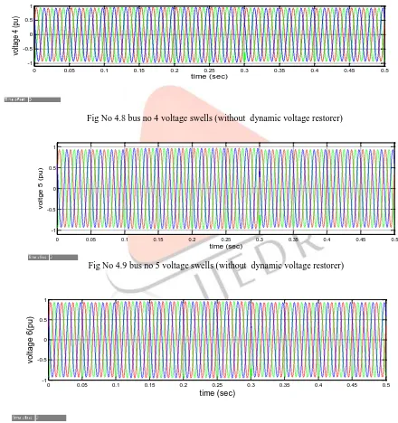
Fig No 4.7 bus no 6 voltage sags (with using dynamic voltage restorer)Voltage swells:
IEEE 9 BUS SYSTEM (without dynamic voltage restorer)
Fig No 4.8 bus no 4 voltage swells (without dynamic voltage restorer)
Fig No 4.9 bus no 5 voltage swells (without dynamic voltage restorer)
Fig No 4.10 bus no 6 voltage swells (without dynamic voltage restorer)
0 0.05 0.1 0.15 0.2 0.25 0.3 0.35 0.4 0.45 0.5
-1 -0.5 0 0.5 1
time (sec)
vo
lta
ge
-6
(p
u)
0 0.05 0.1 0.15 0.2 0.25 0.3 0.35 0.4 0.45 0.5
-1 -0.5 0 0.5 1
time (sec)
vo
lta
ge
4
(
pu
)
0 0.05 0.1 0.15 0.2 0.25 0.3 0.35 0.4 0.45 0.5
-1 -0.5 0 0.5 1
time (sec)
vo
lt
g
e
5
(
p
u
)
0 0.05 0.1 0.15 0.2 0.25 0.3 0.35 0.4 0.45 0.5
-1 -0.5 0 0.5 1
time (sec)
vo
lt
a
g
e
6
(p
u
IJEDR1602124
International Journal of Engineering Development and Research (www.ijedr.org)709
IEEE 9 BUS SYSTEM (with using dynamic voltage restorer)Fig No 4.11 bus no 4 voltage swells (with using dynamic voltage restorer)
Fig No 4.12 bus no 5 voltage swells (with using dynamic voltage restorer)
Fig No 4.13 bus no 6 voltage swells (with using dynamic voltage restorer) VI CONCLUSION
The basic concept of voltage sag and swell is given. In MATLAB SIMULINK, IEEE 9 bus system is modeled and its result is obtained for normal and abnormal condition. From the waveform of abnormal condition, it can be seen that voltage sag takes place in the system due to three phase fault which make the system unhealthy and one need to take care of this. Care of voltage sag and swell can be taken out by using DVR. The simulation results clearly shows the voltage sag and swell due to three phase fault condition in distribution system.
REFERENCES
[1] Debasis Patel, Arup Kumar Goswami ⇑, Santosh Kumar Singh Voltage sag mitigation in an Indian distribution system using dynamic voltage restorer Science Direct Electrical Power and Energy Systems 71 (2015) 231–241.
[2] A. Khoshkbar Sadigh, Student Member, IEEE, and K. M. Smedley, Fellow, IEEE Review of Voltage Compensation Methods in Dynamic Voltage Restorer (DVR) 2012 IEEE.
[3] Mr.Y. Prakash, Research scholar Dept. of EEE and Dr. S.Sankar Professor of EEE Dept. Of EEE “Power Quality Improvement Using DVR in Power System” 2014 Power and Energy Systems: Towards Sustainable Energy (PESTSE 2014) [4] Himadri Ghosh, Pradip Kumar Saha, Goutam Kumar Panda “Performance Comparison between DVR and DSTATCOM Used for Load Voltage Control in Distribution Side” 2012 IEEE
0 0.05 0.1 0.15 0.2 0.25 0.3 0.35 0.4 0.45 0.5
-1 -0.5 0 0.5 1
time (sec)
vo
lta
ge
-4
(p
u)
0 0 .05 0 .1 0 .15 0 .2 0 .25 0 .3 0 .35 0 .4 0 .45 0 .5
-1 -0.8 -0.6 -0.4 -0.2 0 0 .2 0 .4 0 .6 0 .8 1
time(sec)
vo
lta
ge
-5
(pu
)
0 0.05 0.1 0.15 0.2 0.25 0.3 0.35 0.4 0.45 0.5
-1 -0.5 0 0.5 1
time(sec)
vo
lta
g
e
-6
(
p
IJEDR1602124
International Journal of Engineering Development and Research (www.ijedr.org)710
[5] P. Jayaprakash, Member, IEEE, Bhim Singh, Fellow, IEEE, D. P. Kothari, Fellow, IEEE, Ambrish Chandra, Senior Member IEEE, and Kamal-Al-Haddad, “Control of Reduced Rating Dynamic Voltage Restorer with Battery Energy Storage System “2013 IEEE.[6] M. Kanakaraj , Mrs. S. Thirukkovai “ Voltage Sag /Swell Compensation using Fuel cell fed Inverter Base Dynamic Voltage Restorer “ IEEE – international Conference On Advances In Engineering, Science And Management (ICAESM -2012) March 30, 31, 2012
[7] Xueqian Fu, Haoyong Chen, Weike Mo “Dynamic Voltage Restorer Based on Active Hybrid Energy Storage System” 978-1-4799-7537-2/14/$31.00 ©2014 IEEE.
[8] Rakeshwri Pal1, Dr. Sushma Gupta2 “State Of The Art: Dynamic Voltage Restorer for Power Quality Improvement” Electrical & Computer Engineering : An International Journal (ECIJ) Volume 4, Number 2, June 2015.
[9] IEEE Standard 1159-1995 “IEEE Recommended Practice for Monitoring ElectricPower Quality.Published 1995. [10] Richard P. Bingham “Sags and Swells” available from http://www.dranetz-bmi.com/pdf/sags-swells.pdf
[11] H. Hingorani “Introducing custom power” IEEE spectrum, vol.32 no.6 June 1995 p 41-48.
[12] M. H. J. Bollen, “Understanding Power Quality Problems—Voltage Sags and Interruptions” Piscataway, New York: IEEE Press, 2000.
[13] P.T.Nguyen, Tapan K.Saha, “Dynamic voltage restorer against balanced and unbalanced voltage sags: Modelling and simulation”, IEEE transactions on Power Delivery, 2004, pg.1-6.
[14] Yash Pal, A. Swarup, Senior, IEEE, and Bhim Singh, Senior Member, IEEE “A Review of Compensating Type Custom Power Devices for Power Quality Improvement” IEEE Power India Conference, pp. 1-8, 2008.
[15] GHOSH, A., and LEDWICH, G., 2002. Compensation of Distribution System Voltage Using DVR. IEEE Transactions on Power Delivery, 17(4): 1030-1036.
[16] Ankit Pandey, Rajlakshmi ‘Dynamic Voltage Restorer and Its application at LV & MV Level’ International Journal of Scientific & Engineering Research, Volume 4, Issue 6, June-2013 668 ISSN 2229-5518.
[17] Deepa Francis, Tomson Thomas, “Mitigation of Voltage Sag and Swell using Dynamic Voltage Restorer”, International Conference on Magnetics, Machines and Drives (AICERA – 2014 iCMMD)