II. BLOCK DIAGRAM
Fig.2: Block Diagram
A. Silicon Photomultiplier (SiPM)
Silicon Photomultiplier’s are highly sensitive high speed detector. It is used for various applications like detecting a particular particle, PET scan, etc. In this project it is used to detect a high speed photon. The SiPM sensor is made up of avalanche photo diodes (APD’s) in series with quenching resistor. This combination of an APD and a resistor in series is called as a pixel. The APD in SiPM is operated in the geiger mode. In this mode the APD is operated in negative biasing with an extra voltage than the knee point voltage. Due to the extra biasing voltage whenever a photon is incident on the junction of APD it causes avalanche breakdowns giving a gain of 106. Moreover the SiPM is immune to stray electric and magnetic fields and function on considerably low voltage compared to photomultiplier tubes. So SiPM is used for this project.
B. Amplifier
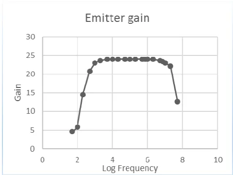
Two stage amplifier with OPAMP stage and TRANSISTOR stage was designed in this project shown in fig.3. We have used OPAMP LMH6629 and TRANSISTOR BFR520. The OPAMP gain is adjusted to 23. OPAMP stage has a high input impedance which will not load the source and provide constant gain. At 2nd stage output is taken from Collector and Emitter terminal, fanout1 will be 180º out of phase with respect to fanout2. The gain of Amplifier can be changed by changing biasing resistors. At Emitter terminal and collector terminal gain is adjusted to 0.9 and 2.0
respectively, thus we have split our signal for other future use. We have obtained bandwidth of 50MHz shown in fig.4. The overall gain of 22.6, Emitter gain variation of 3.75% and Collector gain variation of 3.10% as shown in fig.5 (Testing condition: Collector open and Emitter with matched load of 50 Ω).
Fig.3. Amplifier with Op-amp and Transistor
REFERENCES
[1]Albert Malvino and David J. Bates, Electronics Principle, 7th Ed.
[2]Paul Horowitz and Winfield Hill, the Art ofElectronics, 2nd Ed.
[3]Joëlle Barral, Study of the SiliconPhotomultipliers. [4]E.Atkin, Splitter for Photomultipliers.
[5]S K Gupta, Y Hayashi, A Jain, S Karthikeyan, S
Kawakami, K C Ravindran and S C Tonwar, High Performance Leading Edge Discriminator.
[6] Yuji Miura and Yasuji Suzaki, Development of a High-Speed Differentiation Discriminator For Laser Ranging Systems.
[7] E.Atkin, Yu.Mishin, Yu.Volkov, Analog Signal Splitter. [8] A. Barna and E. L. Cisneroso, Integrated Circuit
Discriminator with 10NSEC Pulse Pair Resolution. [9] R A Shukla, A micron resolution optical scanner fo
characterization of silicon detectors.