International Journal of Scientific Research in Computer Science, Engineering and Information Technology © 2017 IJSRCSEIT | Volume 2 | Issue 5 | ISSN : 2456-3307
An Efficient Lifting Based Architecture for 3D Discrete Wavelet
Transform
J. B. S. Loknath*
1, J. Naga Raju
2*1Department of Electronics and Communication, Malla Reddy Engineering Collage& Management Science‟s, Hyderabad, Telangana, India
2Department of Electronics and Communication, MLR Institute of Technology, Hyderabad, Telangana, India,
ABSTRACT
The digital data can be transformed using Discrete Wavelet Transform (DWT). The Discrete Wavelet Transform (DWT) was based on time-scale representation, which provides efficient multi-resolution. The lifting based scheme (9, 7) (Here 9 Low Pass filter coefficients and the 7 High Pass filter coefficients) filter give lossy mode of information. The lifting based DWT are lower computational complexity and reduced memory requirements. Since Conventional convolution based DWT is area and power hungry which can be overcome by using the lifting based scheme. The discrete wavelet transform (DWT) is being increasingly used for image coding. This is due to the fact that DWT supports features like progressive image transmission (by quality, by resolution), ease of transformed image manipulation, region of interest coding, etc. DWT has traditionally been implemented by convolution. Such an implementation demands both a large number of computations and a large storage features that are not desirable for either high-speed or low-power applications. Recently, a lifting-based scheme that often requires far fewer computations has been proposed for the DWT. In this work, the design of Lossy 3-D DWT (Discrete Wavelet Transform) using Lifting Scheme Architecture will be modeled using the Verilog HDL and its functionality were verified using the Modelsim tool and can synthesized by using the Xilinx tool.
Keywords : DWT, Lifting scheme, Wavelet
I.
INTRODUCTION
The fundamental idea behind wavelets is to analyze according to scale. Indeed, some researchers in the wavelet field feel that, by using wavelets, one is adopting a perspective in processing data.
Wavelets are functions that satisfy certain mathematical requirements and are used in representing data or other functions. This idea is not new. Approximation using superposition of functions has existed since the early 1800's, when Joseph Fourier discovered that he could superpose sines and cosines to represent other functions. However, in wavelet analysis, the scale that we use to look at data plays a special role. Wavelet algorithms process data at different scales or resolutions.
Fourier Transform (FT) with its fast algorithms (FFT) is an important tool for analysis and processing of
many natural signals. FT has certain limitations to characterize many natural signals, which are non-stationary (e.g. speech). Though a time varying, overlapping window based FT namely STFT (Short Time FT) is well known for speech processing applications, a time-scale based Wavelet Transform is a powerful mathematical tool for non-stationary signals.
was Multi-resolution Analysis (MRA) allows DWT to view and process.
II.
METHODS AND MATERIAL
2.1 Discrete Wavelet Transform Architecture
The discrete wavelet transform (DWT) is being increasingly used for image coding. This is due to the fact that DWT supports features like progressive image transmission (by quality, by resolution), ease of compressed image manipulation, region of interest coding, etc. DWT has traditionally been implemented by convolution. Such an implementation demands both a large number of computations and a large storage features that are not desirable for either high-speed or low-power applications.
The proposed architecture computes multilevel DWT for both the forward and the inverse transforms one level at a time, in a row-column fashion. There are two row processors to compute along the rows and two column processors to compute along the columns.
While this arrangement is suitable or filters that require two banded-matrix multiplications filters that require four banded-matrix multiplications require all four processors to compute along the rows or along the columns. The outputs generated by the row and column processors (that are used for further computations) are stored in memory modules.
Recently, a methodology for implementing lifting-based DWT that reduces the memory requirements and communication between the processors, when the image is broken up into blocks. For a system that consists of the lifting-based DWT transform followed by an embedded zero-tree algorithm. A new interleaving scheme that reduces the number of memory accesses has been proposed. Finally, a lifting-based DWT architecture capable of performing filters with one lifting step, i.e., one predict and one update step. The outputs are generated in an interleaved fashion.
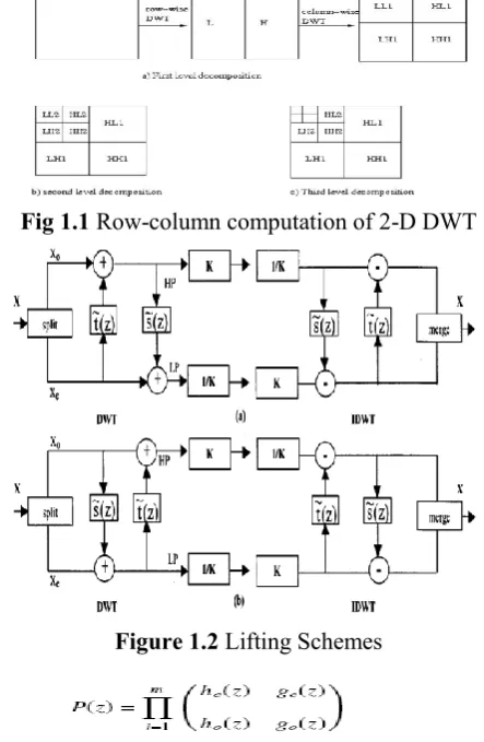
Fig 1.1 Row-column computation of 2-D DWT
Figure 1.2 Lifting Schemes
The basic principle of the lifting scheme is to factorize the poly phase matrix of a wavelet filter into a sequence of alternating upper and lower triangular matrices and a diagonal matrix. This leads to the wavelet implementation by means of banded-matrix multiplications.
2.2 Lifting Implementation of the Discrete Wavelet Transform
As the DWT intrinsically constitutes a pair of filtering operations, a unified representation of the poly-phase matrix is introduced as follows
With λ (z) and γ (z) signifying the filtered low pass and high pass parts of the input x (z).
The lifting scheme factorizes the poly phase representation into a cascade of upper and lowers triangular matrices and a scaling matrix which subsequently return a set of linear algebraic equations in the time domain bringing forth the possibility of a pipelined processor.
For instance, the common Daubechies (9, 7) filter bank can be factorized as
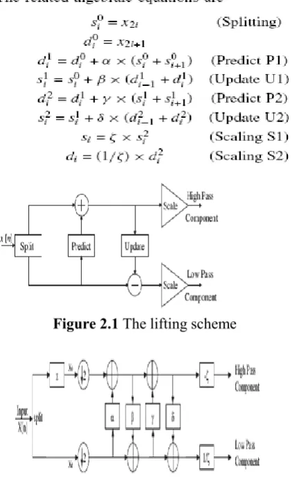
Figure 2.1 The lifting scheme
Figure 2.2 1-D lifting Scheme of daubechies 9/7 for forward wavelet DWT
III. 3D DISCRETE WAVELET TRANSFORM
The 3D DWT can be considered as a combination of three 1D DWT in the x, y and z directions, as shown in Fig. 1. The preliminary work in the DWT processor design is to build 1D DWT modules, which are composed of high-pass and low-pass filters that perform a convolution of filter coefficients and input pixels. After a one-level of 3D discrete wavelet
transform, the volume of image is decomposed into HHH, HHL, HLH, HLL, LHH, LHL, LLH and LLL signals as shown in the Figure
Figure 3.1 3D-DWT Lifting Scheme
The basic idea behind the lifting scheme is very simple; try to use the correlation in the data to remove redundancy. First split the data into two sets (split phase) i.e., odd samples and even samples as shown in Fig. 2. Because of the assumed smoothness of the data, we predict that the odd samples have a value that is closely related to their neighboring even samples. We use N even samples to predict the value of a neighboring odd value (predict phase). With a good prediction method, the chance is high that the original odd sample is in the same range as its prediction. We calculate the difference between the odd sample and its prediction and replace the odd sample with this difference.
We apply these three steps repeatedly on the even samples and transform each time half of the even samples, until all samples are transformed. The bi-orthogonal 9/7 wavelet can be implemented as four lifting steps followed by scaling requires that the following equations be implemented in hardware.
3..2 The 3-D (9, 7) Discrete Wavelet Transform
Initially the Pixel values of any image will be taken with the help of MATLAB, which will be used as the primary inputs to the DWT Block.
Basically 1-D (9, 7) DWT block diagram is developed based on the equations. The registers in the top half will operate in even clock where as the ones in bottom half work in odd clock.
The input pixels arrive serially row-wise at one pixel per clock cycle and it will get split into even and odd. So after the manipulation with the lifting coefficients „a‟,„b‟,„c‟ and „d‟ is done, the low pass and high pass coefficients will be given out. Hence for every pair of pixel values, one high pass and one low pass coefficients will be given as output respectively.
The internal operation of the DWT block has been explained above and hence the high pass and low pass coefficients of the taken image were identified and separated. The generated low pass and high pass coefficients are stored in buffers for further calculations.
Figure 4 Computation of Basic (9,7) DWT Block in which „coefficients „a‟,„b‟,„c‟ and „d‟ are lifting coefficients
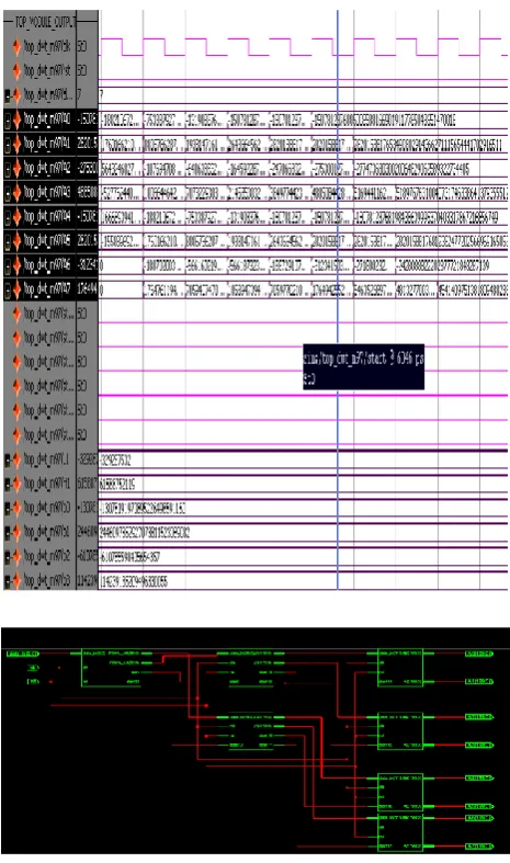
IV. Simulation Results
V.
CONCLUSION AND FUTURE WORK
Basically the medical images need more accuracy without loosing of information. The Discrete Wavelet Transform (DWT) was based on time-scale representation, which provides efficient multi-resolution. The lifting based scheme (9, 7) (The high pass filter has five taps and the low pass filter has three taps) filter give lossless mode of information. A more efficient approach to lossless whose coefficients are exactly represented by finite precision numbers allows for truly lossless encoding.
This work can be extended in order to increase the accuracy by increasing the level of transformations.
This can be used as a part of the block in the full fledged application, i.e., by using these DWT, the applications can be developed such as compression, watermarking, etc.
VI. REFERENCES
[1]. Daubechies and W. Sweldens, “Factoring wavelet transforms into
[2]. lifting steps,” J. Fourier Anal. Appl., vol. 4, no. 3, pp. 247-269, 1998.
[3]. S. Barua, J. E. Carletta, K. A. Kotteri, and A. E. Bell, “An efficient architecture for lifting-based two-dimensional discrete wavelet transforms,” VLSI J. Integration, vol. 38, no. 3, pp. 341-352, Jan. 2005.
[4]. G. Kuzmanov, B. Zafarifar, P. Shrestha, and S. Vassiliadis, “Reconfigurable DWT unit based on lifting,” in Proc. Program Res. Integr. Syst. Circuits, Veldhoven, The Netherlands, Nov. 2002, pp. 325-333.