63
MATLAB Simulink Based Load Frequency Control
Using Conventional Techniques
Rameshwar singh
1, Ashif khan
2Deptt. Of Electrical, NITM, RGPV 1, 2, ,Assistant proff 1 , M.Tech Student2
Email: [email protected], [email protected]
Abstract-This paper present the analysis of tuning the parameters of PID controller and ZN-P,ZN-PI,ZN-PID
controller applied to load frequency control problem .Load Frequency Control (LFC) in power systems is very important in order to supply reliable electric power with good quality. In many industries and domestic application, the speed of the machines depends on the frequency. The load-frequency control (LFC) is used to restore the balance between load and generation in each control area by means of speed control. Load Frequency Controller (LFC) play an important role in maintaining constant. This paper is based on PID tuning approach using traditional Ziegler-Nichols tuning method with the help of Matlab simulink simulation control estimation SISO tools aspects. This paper investigated LFC using proportional integral (PI) Controller and ZN-PID Tuning controller for one area system. The results of the two controllers are compared using MATLAB/Simulink. Comparison results of conventional PI controller and ZN-PID Tuning controller System are presented
Index Terms- PI controller, Ziegler-Nichols -PID, Ziegler-Nichols –P, Ziegler-Nichols –PD,Load Frequency
Control,
1. INTRODUCTION
In recent years electricity has been used to power more sophisticated and technically complex manufacturing processes, and a variety of high-technology consumer goods. These products and process are sensitive not only to the continuity of power supply but also on the quality of power supply such as voltage and frequency [1].In power system operation and control the load is varying continuously and randomly. The varying of load may cause change in real and reactive powers. That means the real and reactive power demands are continuously varying and never steady. If active and reactive powers are changes that may are cause change in system frequency and voltages. But for the successful operation of the system the frequency and voltage should be maintain constant at their normal values [2].In power system, both active and reactive power demands are never steady they continuously change with the rising or falling trend. The changes in real power affect the system frequency, while reactive power is less sensitive to changes in frequency and is mainly dependent on Changes in voltage magnitude. The main purpose of system generation control is to balance the system generation against the load and losses so that the desired frequency and power interchanges between neighboring systems are maintained. The modern power systems with industrial and commercial loads need to operate at constant frequency with reliable power. Load Frequency Control (LFC) is a very important issue in power system operation and control for supplying
Sufficient and reliable electric power with good quality. The main goal of the LFC is to maintain zero Steady state errors for frequency deviation and good tracking load demands in a multi-area restructured power system [3]. Since power system dynamic characteristics are complex and variable, conventional control methods cannot provide desired results. Intelligent controllers can be replaced with conventional controllers to get fast and good dynamic response in load frequency control problems [4]. Many control strategies for Load Frequency Control in electric power systems have been proposed by researchers over the past decades. This extensive research is due to fact that LFC constitutes an important function of power system operation where the main objective is to regulate the output power of each generator at prescribed levels while keeping the frequency fluctuations within prespecifies limits. A unified tuning of PID load frequency controller for power systems via internal mode control has been proposed [5]. During the last decades the researchers have more attention to LFC although the main objective of the control strategy in an interconnected power system is, to generate both voltage and frequency within permissible limits. Recently, lot of research works were documented with an improved transient response by designing proper coupling effects between LFC and AVR and hence proves the necessity of AVR along with LFC. The flows of active power and reactive power in a transmission network are fairly independent of each other and hence this paper deals with individual control mechanism for LFC in order to improve the transient stability of power system [6].
Ziegler-64 Nichols frequency response method and its
Performance has been observed. The most popular tuning technique is the Ziegler-Nichols method. However, besides being suitable only for system with monotonic step response, the compensated system whose controllers are tuned in accordance with the Ziegler-Nichols method have generally a step response with a high- percent overshoot. Ziegler and Nichols proposed the manual tuning of PID controller. The Ziegler Nichols tuned controller parameters are fine tuned to get satisfactory performance.
2. MODELING OF THE PLANT
[image:2.595.73.289.267.397.2]The schematic diagram of the voltage and frequency control loop is represented in Fig.1.
Fig 1 schematic diagram of the voltage and frequency control loop
The schematic diagram of the voltage and frequency control loop is represented in fig.1. The controllers are set for a particular operating condition and take care of small changes in load demand to maintain the frequency and voltage magnitude within the specified limits. Small changes in real power are mainly dependent on changes rotor angle δ and, thus, the frequency f. The reactive power is mainly dependent on the voltage magnitude (i.e. on the generator excitation). Change in angle δ is caused by momentary change in generator speed. Therefore, load frequency and excitation voltage controls are non-interactive for small changes and can be modeled and analyzed independently. Furthermore, excitation control is fast acting while the power frequency control is slow acting since, the major time constant contributed by the turbine and generator moment of inertia-time constant is much larger than that of the generator field. Thus, the cross-coupling between the LFC loop and the AVR is negligible, and the load frequency and excitation voltage control are analyzed independently [1].
3. Load frequency control of single area
The aim of LFC is to maintain real power balance in the system through control of system frequency. Whenever the real power demand changes, a
frequency change occurs. This frequency error is amplified, mixed and changed to a command signal which is sent to turbine governor. The governor operates to restore the balance between the input and output by changing the turbine output. This method is also referred as Megawatt frequency or Power frequency (P-f) control [7]. For the satisfactory operation of power system the frequency should be maintained constant. The considerable drop in frequency in any electrical network could result in high magnetizing currents in induction motors and transformers. So it is essential to regulate the frequency which is a common factor throughout the system. Moreover, the change in active power depends on frequency deviations and hence, the change in frequency in any point of the interconnected power system may affect the active power throughout the system [8].Maintain the frequency to its nominal value, Maintain optimal power flow between control areas and Maintain economical power generation in individual generating units.
4. PID controller with tuning with Ziegler-Nichols method
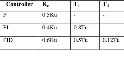
[image:2.595.309.518.625.722.2]The most popular tuning methodology was proposed by Ziegler and Nichols in 1942. PID controller‘s on line auto tuning that is based on Ziegler Nichols tuning method. It is a simple method of tuning PID controllers and can be refined to give better approximations of the controller. Over the 1940s, many methods have been developed for obtaining the P, I, D controller parameters. In this work the technical PI controller method is compared with the traditional technique Ziegler-Nichols PID controller. In 1942, Ziegler and Nichols proposed two experimental approaches to quickly adjust the controller parameters without knowing the precise dynamic model of the system to adjust. Both methods are empirical and based on tests. In this paper we use the second method of Ziegler-Nichols, it is a simple technique to tuning P, I, D controller parameters [9].in this paper used PID tuning parameter show in the table 1.
Table 1 Fast PID controller parameters using Ziegler– Nichols closed-loop method
Controller Kc Ti Td
P 0.5Ku - -
PI 0.4Ku 0.8Tu
PID 0.6Ku 0.5Tu 0.12Tu
5 .PID CONTROLLER
65 system so reducing the steady state error. System load
[image:3.595.74.291.221.288.2]is never steady using this controller these can be controlled. When uncontrolled case more oscillation, negative overshoot be observed but while comparing to conventional type controller PID and propose work result gives better [10].The controller constants Kp, Ki and Kd can be obtained for a system with feedback. The advantage of Z-N PID controller tuning is also carry out for higher order systems Matlab simulink model show in the fig 4. And PID parameter show in the table 2.
Table 2 PID parameter
Ki kp kd
3.925 8.1472 15.762
6. PI CONTROLLER
A P controller system is a type of linear feedback control system. The P controller system is more complex than on-off control systems like a bi-metallic domestic thermostat, but simpler than a PID control system used in something like an automobile cruise controlling general it can be said that P controller cannot stabilize higher order processes [11]. In this paper tuning of PI controller value of K for system, matlab simulink model show in the fig 3 for system KI is 20 or gain is 0.925.
7.0 SIMULATION RESULTS
[image:3.595.305.534.450.711.2]The simulation has been conducted in MATLAB (R2010a) for single area power system with PI and Z N PID tuning controller is design for Power plant model. In the simulink model the controller block ofblock diagram 2 is replaced by PI controller and ZN-PID controller.
Fig 2. Block Diagram of PI Controller And ZN-PID Controller.
The frequency deviations in POWER area studied under PI controller and ZN-P, ZN-PI AND ZN-PID
controller actions. The single area power system parameters consisting of the speed governor, turbine and generator are given in Table 3. Here the governor free operation is assumed and load demand ∆PL = 0.01.
Table 3: Parameters of single area system [12]
S.No Parameter name value
1 Governor gain 1
2 Governor time constant 0.1
3 Turbine gain 1
4 Turbine Time Constant 0.3
5 Load model 6
6 Load time constant 0.6
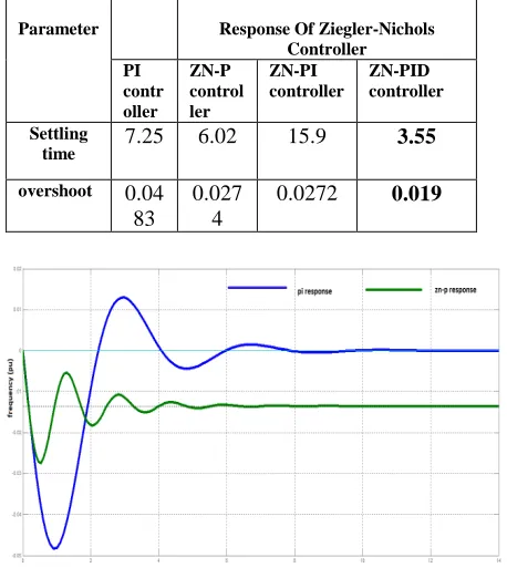
For conventional PI controllers Ki is taken as 20 and R = 3.935 .The values of PID Parameters as obtained by ZN-PID optimization: Kp = R = 3.935; Ki = 8.1472; Kd = 1.5761; Simulation results for the single area power system are shown in Table 4. As can be observed, the settling time and overshoots with the proposed PI and ZN-P,ZN-PI AND ZN-PID TUNING controller are much shorter than that of with the conventional PI controller ,result are show in the fig 3,fig 4 and fig 5. Therefore, the ZN-PID controller provides better performance than conventional PI controller.
Table 4 comparative analysis for different controller
Parameter Response Of Ziegler-Nichols
Controller PI
contr oller
ZN-P control ler
ZN-PI controller
ZN-PID controller
Settling
time 7.25 6.02 15.9 3.55
overshoot 0.04
83
0.027 4
0.0272 0.019
[image:3.595.75.289.538.665.2]
66 Fig 4 Frequency Deviation of Single area PID
controller and ZN-PI controller
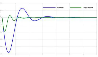
Fig 5 Comparison of Frequency Deviation of Single areas with PI and ZN-PID controller
Conclusion
The quality of the power supply is determined by the constancy of frequency. In this paper, the tuning of PI controller and Ziegler-Nichols PID Tuning controller was proposed to solve the load frequency control problem of single area power system. Simulation results show that Ziegler-Nichols PID Tuning controller is frequency deviations of power system has a better performance than the PI controller because reduced the settling time and minimize overshoot, Z-N Tuned PID controller with simple approach can provide better performance comparing with the conventional PI controller,that the proposed ZN-PID Controller can search the optimal parameters of LFC quickly & efficiently.
REFRENCES
[1]T.R Shyama, R Satheesh Kumar, V Shanmugasundaram, “Design of FGSPI Controller Based Combined LFC and AVR of Two Area Interconnected Power Generating System” International Journal of Engineering and Advanced Technology (IJEAT) ISSN: 2249 – 8958, Volume-1, Issue-4, April 2012.
[2] T.C. Srinivasa Rao, Ravi Ponnala, “Frequency Error and Voltage Control by using PI and Fuzzy Logic Controllers for Multi Area Inter Connected Power System”,International Journal
of Computer Applications (0975 – 8887) Volume 77– No.2, September 2013.
[3] T. Hussein, “A Genetic Algorithm for Optimum Design of PID Controller in Load Frequency Control”, International Scholarly and Scientific Research & Innovation, World Academy of Science, Engineering and Technology Vol:6 2012-10-24.
[4] H.D. Mathur and S. Ghosh, “A Comprehensive analysis of intelligent controllers for load frequency control,” IEEE Power India Conference, 10.1109/POWER.
[5] M. A. Tammam1, M. A. S. Aboelela2, “Fuzzy Like PID Controller Tuning By Multiobjective Genetic Algorithm For Load Frequency Control In Nonlinear Electric Power Systems”, International Journal of Advances in Engineering & Technology, Nov. 2012, ISSN: 2231-1963.
[6]Saumya Kr. Gautam, Nakul Goyal, “Improved Particle Swarm Optimization BasedLoad Frequency Control in a Single Area Power System”, 2010 Annual IEEE India Conference (INDICON), 978-1-4244-9074-5/10/$26.00 ©2010 IEEE.
[7] A. Soundarrajan1, S. Sumathi2 and G.Sivamurugan3, “Hybrid Evolutionary Algorithms For Frequency And Voltage Control In Power Generating System”, Ictact Journal On Soft Computing, October 2010,issue 02.
[8] Anbarasi S#1, Mur alidharan S*2, “Transient Stability Improvement Of LFC And AVR Using Bacteria Foraging Optimization Algorithm” 2014 IEEE International Conference on Innovations in Engineering and Technology (ICIET’14), Volume 3, Special Issue 3, March 2014.
[9] N.EL.Y. Kouba, M. Menaa, M. Hasni, B. Boussahoua, and M. Boudour, “Automatic Generation Control in Interconnected Power System with Integration of Wind Power Generation Using PID Controller Based on Particle Swarm Optimization”, International Conference on Renewable Energies and Power Quality (ICREPQ’14), ISSN 2172-038 X, No.12, April 2014.
[10] 1K Smriti Rao, 2Ravi Mishra, “Comparative study of P, PI and PID controller for speed control of VSI-fed induction motor” 2014 IJEDR | Volume 2, Issue 2 | ISSN: 2321-9939 [11] Atul Ikhe, Anant Kulkarni, “Load frequency
control for interconnected power system using different controllers” Automation, Control and Intelligent Systems 2013; 1(4): 85-89
[image:4.595.81.287.262.382.2]67 Particle Swarm Optimization Technique”
International Journal of Scientific Research Engineering & Technology (IJSRET), ISSN 2278 – 0882 Volume 3, Issue 5, August 2014. [13]Saumya Kr. Gautam, Nakul Goyal, “Improved
Particle Swarm Optimization Based Load Frequency Control in a Single Area Power System”, 2010 Annual IEEE India Conference (INDICON), 978-1-4244-9074-5/10/$26.00 ©2010 IEEE.
[14] K.J. Astrom,T.Hagglund “Revisiting the Ziegler– Nichols step response method for PID control”, www.elsevier.com/locate/jprocont, Journal of Process Control 14 (2004) 635–650 .