Alternate Rectangular Slots loaded Proximity
Fed Antenna
Dinesh B. Ganure1, S. L. Mallikarjun2, P. M. Hadalgi3
Research Scholar, Department of Applied Electronics, Gulbarga University, Kalaburagi, Karnataka, India1 Guest Faculty, Department of Applied Electronics, Gulbarga University, Kalaburagi, Karnataka, India 2
Professor, Department of Applied Electronics, Gulbarga University, Kalaburagi, Karnataka, India3
ABSTRACT: This paper presents the effect of alternate slots on rectangular microstrip patch antenna using proximity feed technique. The fabricated antenna uses two-layer substrate with the microstrip-line on the lower layer and the patch antenna on upper layer such as the feed line terminates in an open end underneath the patch. In this study four alternate rectangular slots are etched on a rectangular patch such that four alternate rectangular patches are formed where each patch is resonating for different frequency by providing quad band operation. The other antenna parameters such as radiation pattern, return loss, gain, VSWR and HPBW are presented and discussed. The proposed antenna finds the application in modern wireless communication systems.
KEYWORDS: Microstrip antenna, proximity feed, quad band, gain and VSWR.
I. INTRODUCTION
In the present-time communication, antennas cover a wide range of applications in different areas, such as mobile communication, satellite navigation, internet services, automobiles and radars. Especially they are applied to microstrip antennas, because of its characteristics like low profile, lightweight and low power handling capacity [1-4]. However, gain and bandwidth are sometimes low and not sufficient in most of applications. Modification of shape and using special materials could be useful to solve such backlashes of this type of antennas. Therefore it becomes very important to develop a technique to increase the bandwidth and gain of the microstrip antenna.
In modern wireless communication GPS, Bluetooth, WLAN and WiMAX have been widely applied in mobile devices such as hand held computers and smart phones. These two techniques have been widely recognized as a viable, cost-effective, and high- speed data connectivity solution, enabling user mobility with the rapid development of the modern wireless communication system, antenna design has turned to focus on wide multiband and small simple structures that can be easy to fabricate. Compact, multiband, low-profile and low-cost antennas are widely used in personal communication devices along with the rapid development of the wireless communication systems. Similarly various studies on slots have seen in the literature in order to achieve two or more than two band operations were reported. A quad-band U-slot microstrip patch antenna using co-axial feeding technique for wireless application is presented [5]. Design of quad band operation of antenna at four different bands of frequencies which is possible by constructing two rhombus slots on rectangular microstrip patch element [6]. A new quad-band small size microstrip handset antenna is designed using different substrate material [7]. A single feed dual layer rectangular microstrip antenna with single short pin which gives quad-band antenna can operate effectively in four frequency bands [8].
II. ANTENNA DESIGN
The proposed antenna using proximity feeding technique is fabricated using a commercially available low cost glass epoxy substrate material with relative permittivity εr= 4.2 and dielectric loss tangent tan δ = 0.02.
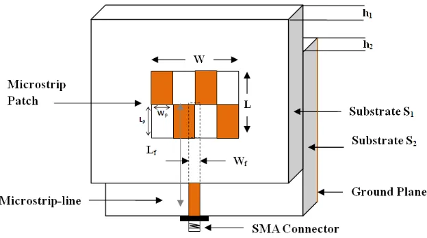
Figure 1 shows geometry of the proposed antenna. It consists of four rectangular slots on top surface of substrate S1.
The microstripline feed of length Lf = 24.971 cm and width Wf = 3.166 cm is etched on the top surface of substrate S2.
The substrate S2 is placed below substrate S1 and the bottom surface of the substrate S2 acts as the ground plane of
dimension Lg = 33.570 cm and Wg = 40.608 cm.
Fig. 1 Geometry of proposed antenna
The proposed has been designed for 3 GHz. The art work of the proposed antenna is sketched by using computer software Auto-CAD 2006 to achieve better accuracy and the substrate material of thickness of h = 1.66 mm is same for two layers. At the tip of microstrip feed line, a 50 Ω coaxial SMA connector is connected for feeding the microwave power.
III.EXPERIMENTAL RESULTS
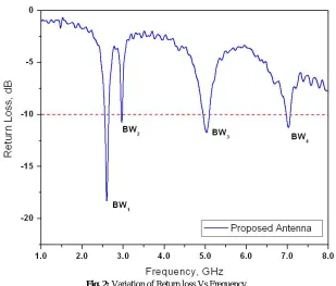
The measurements are taken on Vector Network Analyzer (Rohde & Schwarz, German make ZVK Model No. 1127.8651). The impedance bandwidth over return loss less than -10dB for the proposed antenna is measured which is shown in Figure 2. The experimental impedance bandwidth is defined as,
Impedance Bandwidth (%) = ... (1)
Fig. 2: Variation of Return loss Vs Frequency
From the figure it is observed that, antenna operates for quad band of frequencies at 2.61 GHz, 2.96 GHz, 5.02 GHz and 7.02 GHz. The experimental impedance bandwidth (BW1) at 2.61 GHz is found to be 87 MHz (3.36%), at 2.96
GHz the impedance bandwidth (BW2) is 17.5 MHz (0.58%), at 5.02 GHz the impedance bandwidth (BW3) is 157.5
MHz (3.13%) and the impedance bandwidth (BW4) at 7.02 GHz is 105 MHz (1.49%). Similarly the minimum return
loss measured in this antenna is found to be -18.75 dB, -11.18 dB, -11.75 dB and -11.27 dB respectively.
The X-Y plane co-polar and cross-polar radiation patterns of antenna are measured at their resonating frequencies and the radiation pattern at 2.61 GHz is shown in Figures 3. The figure indicates that the antenna shows broader side radiation characteristic. The cross-polarization level of this antenna is found to be below -11dB.
Fig. 3: Radiation pattern at 2.61 GHz
…….. (2)
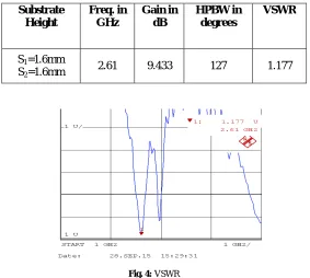
where, Pt and Pr are transmitted and received powers respectively, Gt is the gain of the pyramidal horn antenna and R is the distance between transmitting antenna and antenna under test. The gain of the antenna is tabulated in Table 1. Similarly, Voltage Standing Wave Ratio (VSWR) is found to be 1.177 and this corresponds to a perfect match [11] which is shown in Figure 4.
Table 1: Calculated Gain, HPBW and VSWR
Substrate Height
Freq. in GHz
Gain in dB
HPBW in degrees
VSWR
S1=1.6mm
S2=1.6mm 2.61 9.433 127 1.177
Fig. 4: VSWR
The input impedance shown has a loops at the center of Smith chart which validated its quad band nature and the impedance matching is found at 42.53-j2.236 which illustrates the nearly matching of the feedline and radiating patch at 50Ω to the standard [6] which is shown in Figure 5.
0 0.2 0.5 1 2 5 10
-5
-2
-1 -0.5
0.5
1
2
5
CH1 1 U
START 2.5 GHz STOP3.1 GHz
FIL 1k 1k FIL 1k 1k S11
1
1: 42.53 -j2.236
2.608 GHz
IV.CONCLUSION
The experimental study illustrates that the antenna is relatively simple in design and fabrication and quite good in enhancing the bandwidth by quad frequency operation and giving better broadside radiation pattern. The other antenna parameter return loss, gain and VSWR are found to be good for this antenna. This antenna is better as it uses low cost substrate material and finds applications in S and C-band frequency ranges such as in modern wireless communication systems.
ACKNOWLEDGEMENTS
The authors would like to thank the Department of Science and Technology, New Delhi for sanctioning the Vector Network Analyzer to our Department under FIST program.
REFERENCES
[1] I. J. Bahl and P. Bhartia, Microstrip Antennas, Artech House, Dedham, MA, 1980.
[2] Fan Yang; Xue-Xia Zhang; Xiaoning Ye; and Yahya Rahmat-Samii, “Wide-Band E-Shaped Patch Antennas for Wireless Communications”,
IEEE Trans. Antennas Propog. Vol. 49, No. 7, 2001.
[3] Girish Kumar and K. P. Ray, Broadband Microstrip Antennas, Norwood, MA: Artech House, 2003.
[4] David M. Pozar, Microwave Engineering, Addison Wesley Publishing Company, Inc. 1990.
[5] Swaraj Panusa and Mithlesh Kumar, “Quad-band U slot Microstrip patch antenna”, International Journal of Scientific Research Engineering
and Technology, Vol. 3, Issue 1, pp.145-148, April 2014.
[6] Ambresh P. A., A. A. Sujata, A. M. Khan, P. M. Hadalgi, and P. V. Hunagund, “Quad Band Rectangular Microstrip Antenna for S and C-Band
Applications”, International Journal of Computer and Communication Engineering, Vol. 3, No. 5, pp.334-337, September 2014.
[7] Asem S. Al-Zoubi, Mohamed A. Moharram, “Quad-Band Microstrip Antenna for Mobile Handsets”, Journal of Theoretical and Applied
Information Technology, Vol. 60 No.1 pp. 106-111, February 2014.
[8] Gada Mahamood Faisal, Kaydar Majeed Quboa and Dia Mohamad Ali, “Quad band dual layer microstrip antenna design for mobile handset”,
American Journal of Electrical and Electronics Engineering, Vol. 2, No. 2, pp. 51-56, 2014.
[9] B. G. Dinesh, S. L. Mallikarjun, G. M. Pushpanjali and P. M. Hadalgi, “Diagonal slot-loaded rectangular microstrip patch antenna”, Indian Journal of Scientific Research, Vol.12, Special Issue No. 1, pp.214-216, 2015.
[10] Ramesh Garg, “Microstrip Antenna Design Handbook”, Artech House, Noorwood, MA, 2001.
[11] John R. Ojha and Marc Peters, “Patch antennas and Microstriplines”, Intechopen, Germany, 2014.
BIOGRAPHY
Mr. Dinesh B. Ganure received his M.Sc., M.Phil degree in Applied Electronics from Gulbarga University, Kalaburagi in the year 2010, 2013 respectively. He is working as a Research Scholar in Dept. of Applied Electronics, Gulbarga University, Kalaburagi. He is an active researcher in the field of Microwave Electronics.
Dr. S. L. Mallikarjun received his M.Sc., M.Phil. and Ph.D. degree in Applied Electronics from Gulbarga University, Kalaburagi in the year 2005, 2007 and 2011 respectively. He is working in Dept. of Applied Electronics, Gulbarga University, Kalaburagi. He is an active researcher in the field of Microwave Electronics. His area of interest includes microstrip antenna, arrays and dielectric resonator antenna. He has more than 70 publications in reputed International/National Journals and in conference and symposia.