ABSTRACT
POLIT, SEBASTIAN. Development of a High Throughput Nano-Positioning System with Applications in Micro-Manufacturing. (Under the direction of Dr. Jingyan Dong).
The second part is the development of a high throughput two dimensional nano-positioning stage using the previously developed nano-positioning modules as building blocks. Two nano-positioning modules are assembled together and two additional double clamped beams are integrated to the system in order to produce the desired device. The new integrated beams provide high stiffness to the system, while the hybrid modules decoupled the two axis displacement. As a result, a high bandwidth system that is capable of providing well controlled independent displacement in two dimensions is obtained. Theoretical analysis is presented to explain the design parameters and their effect in the system’s behavior. FEA analysis is performed to simulate and optimize the system, and to confirm the results obtained in the theoretical analysis. Manufacturing and assembly processes are described and the manufactured final device is tested using high bandwidth piezoelectric actuator and capacitance sensors to complete the assembly. Static and dynamic responses are then experimentally tested and the desired high throughput required for the possible applications is verified.
Development of a High Throughput Nano-Positioning System with Applications in Micro-Manufacturing
by Sebastian Polit
A thesis submitted to the Graduate Faculty of North Carolina State University
in partial fulfillment of the requirements for the degree of
Master of Science
Industrial Engineering
Raleigh, North Carolina 2010
APPROVED BY:
______________________________ ______________________________
Dr. Yuan-Shin Lee Dr. Yong Zhu
Chair of Advisory Committee BIOGRAPHY
Sebastian Polit was born in Quito, Ecuador on October 02th, 1977. He graduated from Metropolitano high school of Quito in 1995. He obtained his degree in Mechanical Engineering from the Escuela Politécnica del Ejército (ESPE), at Quito, in 2001. After graduation, he worked for a year as maintenance manager assistant in KFC Ecuador. Then, he worked 6 years as design engineer for CODIPLA (Construction, Design and Planning).
ACKNOWLEDGMENTS
I would like to thank Dr. Jingyan Dong, my academic advisor, for his guidance and help, which have been of fundamental importance in the completion of this work. I would also like to thank the professors that have been part of my graduate education as teachers or through my research process. Thanks too to the laboratory personnel for all their help, advice and support.
I am grateful to the Fulbright Program and the Department of Industrial and Systems Engineering at North Carolina State University for the financial support that allowed me to pursue my Master’s degree, and to enjoy this great academic and life experience. Thanks to all my friends that have been an important support during my years of study.
TABLE OF CONTENTS
LIST OF TABLES ... vi
LIST OF FIGURES ... vii
CHAPTER 1: INTRODUCTION ... 1
CHAPTER 2: Single degree of freedom nano-positioning module ... 5
2.1 Introduction ... 5
2.2 Comparison between different single degree-of-freedom flexure mechanisms ... 7
2.3 Analysis of hybrid compliant-notch flexure mechanism ... 11
2.4 Results from finite elements analysis ... 17
2.5 Application of the hybrid flexure modules ... 26
2.6 Conclusions ... 28
CHAPTER 3: Two degrees of freedom nano-positioning system ... 30
3.1 Introduction ... 30
3.2 Mechanical design and kinematic analysis ... 34
3.4 Design Considerations for a high-bandwidth stage ... 49
3.5 Finite Elements Analysis and Results ... 52
3.6 Experimental results ... 57
3.7 Conclusions ... 65
CHAPTER 4: Micro-milling using the designed hybrid two DOF nano-positioning stage ... 67
4.1 Introduction ... 67
4.2 Methodology ... 70
4.3 Set up and practical considerations ... 71
4.4 Machining variables calculations ... 74
4.5 Experiments results ... 76
4.6 Conclusions ... 80
CHAPTER 5: Conclusions and recommendations ... 82
LIST OF TABLES
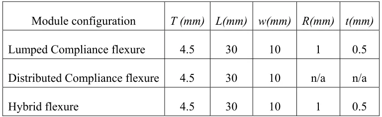
Table 1: Model parameters used in Figure 4: Dominant resonant modes for the three flexure configurations. ... 19
LIST OF FIGURES
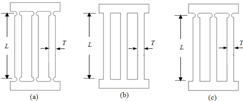
Figure 1: Different configurations of single degree-of-freedom flexure structures. (a) Lumped- compliance flexure. (b) Distributed-compliance flexure. (c) Hybrid
compliant-notch flexure design. ... 8
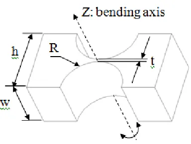
Figure 2: Parameters for notch flexure hinges design ... 12
Figure 3: Illustration of the hybrid compliant-notch flexure mechanism. ... 14
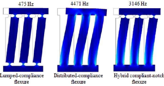
Figure 4: Dominant resonant modes for the three flexure configurations. ... 18
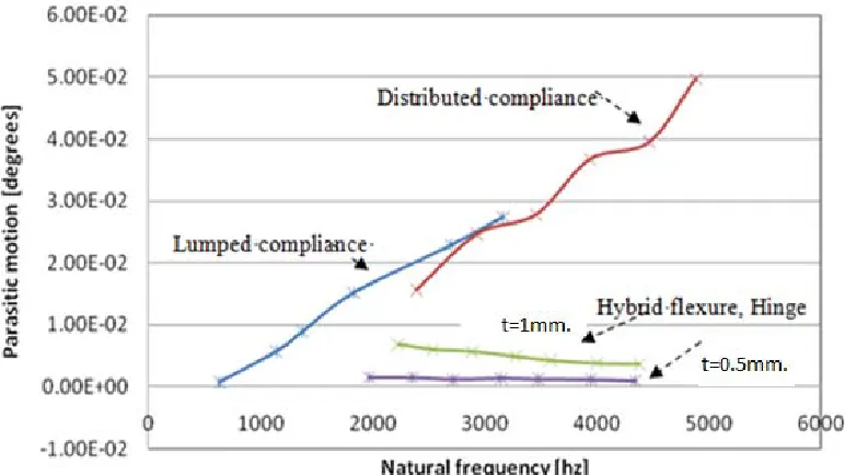
Figure 5: Structural frequency vs. parasitic Abbe/sine error for different configurations. ... 20
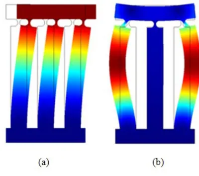
Figure 6: Modal shapes of 1st and 2nd modes. (a) 1st mode (3146 Hz) (b) 2nd mode (15512 Hz) ... 23
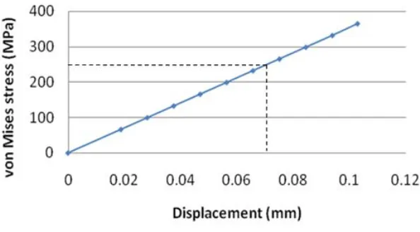
Figure 7: The maximum Von Mises stress with respect to displacement... 24
Figure 8: (a) Stress distribution and (b) Stress distribution at a flexure hinge, (c) total displacement distribution (multiplied by 40). ... 24
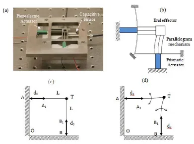
Figure 10: (a) Mechanical structure of the XY nanopositioning system (b) Schematic representation of the system (deformed system when x axis is actuated) (c, d) Equivalent linkage of the parallel kinematics XY stage for the purpose of analysis at the nominal position and under actuation. ... 34
Figure 11: Illustration of the hybrid compliant-notch parallelogram flexure module. ... 35
Figure 12: Stage displacement under different actuation force. ... 53
Figure 13: (a) Stress distribution of the deformed mechanism with deformation magnified by 100. (b) Stress distribution around the flexure hinges. ... 54
Figure 14: Vibration modes and their corresponding frequencies. ... 55
Figure 15: Out of plane displacement under Z load. ... 57
Figure 16: (a, c) Experimentally measured static displacement with respect to actuation voltage for one axis. (b, d) Cross-coupled displacement from the other axis. ... 58
Figure 17: Steady state noise level... 59
Figure 18: Noise histogram of steady state sensor measurements. ... 60
Figure 20: Closed-loop step response in X (left) and Y (right) directions. ... 63
Figure 21: Closed-loop stepwise motion. ... 64
Figure 22: Histogram of closed-loop steady state error ... 64
Figure 23: Set up for the proposed micro machining process. ... 72
Figure 24: Achieved surface finish compared with mirror like (#8). ... 78
Figure 25: Tool trajectory used in the G-CODE program. (a) Total surface trajectory. (b) Different considered sectors. ... 79
Figure 26: 2 x 10 um letters in a 50 um size square machined in aluminum using tungsten tip. ... 79
CHAPTER 1: INTRODUCTION
Micro and nanotechnology have become increasingly important for the industry over the recent years. Broadly, the term nanotechnology means “the study, development and processing of materials, devices and systems in which structure on a dimension of less than 100 nm is essential to obtain the required functional performance” [1]. As a reference, the raw human eye can resolve features of around 20 um, it is 2x10⁴ nm. Nanotechnology is experiencing this fast development due to the high demand of low cost complex products with low requirements in energy and materials. Miniaturization is in fact an effective way to decrease the products’ requirements for material and energy, and potentially lead to cheap production processes with almost no waste of resources.
Currently, nanotechnology has been applied to many increasingly important industries. For example, it is used in advanced optics to machine the mirrors used in X-ray telescopes that require nanometer accuracy. In addition, micro-features machined in integrated circuits are common in electronic industry. In a word, nanotechnology has been successfully applied to fields that go from aerospace industry, computer disks and semiconductor devices, to medicine, biotechnology and environmental protection industries.
nano-positioning systems (X, Y, θ) are required in submicron lithography [3]. In micro-machining in particular, atomic force microscopes (AFM) using high speed nano-positioners have been used to scratch metal surface at nanometer scale [4].
Some work has been done to develop high speed and accuracy micro-positioning stages. For instance, a novel parallel kinematic mechanism for integrated, multi-axis nano-positioning has been proposed in [5] and [6]. However, the continuously developing nano-scanning and nano-manufacturing applications for these devices in current industry, such as AFM scanners or nano-manufacturing through atomic manipulation, require throughputs that have not been achieved yet. For this reason, the development of novel devices that can achieve such characteristics is an active and important field of research.
For the first part, flexure structures and parallel mechanisms concepts are integrated to design the mentioned one degree of freedom (1 DOF) nano-positioning module. High speed and nanometer accuracy are the two main characteristics that this new design is focused on achieving. Theoretical analysis and FEM simulation are used to verify the effectiveness of this new design regarding the required characteristics.
In the second part, additional elements are integrated to these modules and are combined to generate a high throughput two degrees of freedom (2 DOF) nano-positioning stage. This new system is successfully designed, analyzed theoretically, tested through FEM simulation and finally experimentally tested in the laboratory. For the experimental tests, piezoelectric actuators and capacitance sensors are used to generate the desired displacement and register the obtained output respectively. The three used analyses, e.g. theoretical, FEM and experimental analyses verify the good mechanical characteristics of this new design. A closed loop configuration is also attempted using a DSP-based (Digital Signal Processing based) motion controller and the possibility of operating the new nano-positioning system in this configuration with good throughout is also verified.
CHAPTER 2: Single degree of freedom nano-positioning module
2.1 Introduction
Structural frequency (open-loop bandwidth) becomes a critical requirement for the nano-positioner in high-throughput nano-manufacturing and metrology applications. Most of nanoscale manipulators and manufacturing processes have extremely fast speed. For example, the micro cantilevers that are used in scanning probe microscopes [17, 18, 19, 20, 21] and dip-pen nano-lithography [22, 23, 24] have bandwidths over 10-100 kHz. Fast manipulation and manufacturing processes place increasingly demanding performance requirements on nano-positioning systems. The slow response speed of nano-positioners (normally <500 Hz) becomes a bottle neck for achieving the high-throughput nano-manufacturing.
In this chapter, a hybrid compliant-notch flexure-based single degree-of-freedom nano-positioning module is designed for achieving the desired mechanism with high structural bandwidth (i.e. natural frequency), while keeping the parasitic motion at a very low level. This flexure design decouples the performance requirements for the structural bandwidth and parasitic accuracy that are correlated in the lumped-compliance mechanisms and distributed-compliance mechanisms. The designed parallelogram hybrid compliant-notch flexure mechanism enables simultaneous achievement of a higher structural bandwidth and a smaller parasitic motion. Results from finite element analysis demonstrate the effectiveness of this hybrid compliant-notch flexure over widely used compliant mechanisms and notch flexure mechanisms, especially when a high bandwidth is needed from the flexure mechanisms. The resulted one degree-of-freedom nano-positioning modules can be used as building blocks for multi-degree-of-freedom (XY, XYZ) micro/nano-positioning and manufacturing applications. By assembling two or more nanopositioning modules together, customized multiple degrees-of-freedom systems can be built conveniently for variant applications.
2.2 Comparison between different single degree-of-freedom flexure mechanisms
Figure 1: Different configurations of single degree-of-freedom flexure structures. (a) Lumped-
compliance flexure. (b) Distributed-compliance flexure. (c) Hybrid compliant-notch flexure design.
of the flexure hinges, so as to obtain a larger structural stiffness. Although the main objective (high bandwidth) can be achieved in this way, the parasitic motion at the end-effector of the resulted mechanism will increase considerably, because the assumption that a flexure-hinge based joint is very close to an ideal rotary joint is not valid when the dimension of the flexure joint is too large. As a result, the natural frequency of the lumped-compliance flexure mechanism is increased at the cost of increasing the parasitic motion and sacrificing the positioning accuracy.
base. As a result, a large undesired parasitic rotation is generated. For this configuration, a high structural frequency can be achieved through increasing the width of the beam, T. However, larger beam width indicates larger nonlinearity in its deformation and larger parasitic motion. Generally, the distributed compliance configuration is capable of achieving a high bandwidth, but the parasitic motion is very large and the accuracy is not satisfactory.
better than the lumped compliance flexure-mechanism when the bandwidth of the mechanism is high enough. The advantage of this hybrid compliant-notch flexure configuration is the decoupling of two contradicting performance specifications (i.e. structural bandwidth and parasitic Abbe/sine error). The hybrid flexure mechanism can be designed with high bandwidth (by increasing the beam width), and at the same time very small parasitic motion error (by decreasing the thickness of the notch flexure hinge) can be obtained. With this configuration, a device with high open-loop bandwidth and low parasitic motion error can be designed to satisfy the requirements of many precision and high-rate applications. The trade-off of this hybrid flexure design is its relatively small range-of-motion compared with the distributed compliance flexure mechanism, due to the large rotational motion of the notch-flexure-hinges in this mechanism required to obtain the same end-effector displacement. However, this disadvantage can be compensated by designing flexure-hinges with small thickness, so as to enlarge the maximum allowed rotational motion of the flexure-hinges and to increase the overall displacement range of the mechanism.
2.3 Analysis of hybrid compliant-notch flexure mechanism
beams plus the mass of the top linkage. The stiffness of a single beam is described as follows:
𝑘 =𝐸𝑤𝑇
4𝐿
(2.1)
where E is Young’s modulus of the material of the compliant structure, w is the device thickness, T is the beam width, and L is the length of the beam. Since the new design has multiple (3) beams as a multi-parallelogram structure, the overall stiffness is as follows:
𝐾 = 𝑛𝑘 = 𝑛EwT3
4L3
and 𝑛 = 3.
The design parameters for the single-axis circular flexure hinge are shown in Figure 2.
Figure 2: Parameters for notch flexure hinges design
𝑐 = 1 𝑘 = 𝛼 𝑀 = 3 2𝐸𝑤𝑅 1
2𝛽 + 𝛽 𝑥 (2.2)
1 + 𝛽 𝛾 +
3 + 2𝛽 + 𝛽
𝛾. (2𝛽 + 𝛽 ) . 1 − (1 + 𝛽 − 𝛾) +
6. (1 + 𝛽) (2𝛽 + 𝛽 ) . 𝑡𝑎𝑛
2 + 𝛽 𝛽 𝑥
(𝛾 − 𝛽) 1 − (1 + 𝛽 − 𝛾)
Where β = t/2R; γ = h/2R; E is the Young’s Modulus of the material of the flexure hinge; αz is the angular deformation of the hinge about Z-axis in radians and Mz is the external bending torque applied to the flexure hinge. In the parallelogram mechanism, when the end-effector of the mechanism is actuated, all the flexure hinges undergo the same deflection, thus the rotary stiffness from the flexure hinges is 𝐾 = 𝑛 = 𝑛𝑘 .
Figure 3: Illustration of the hybrid compliant-notch flexure mechanism.
As shown in Figure 3, a force is applied to the end-effector to generate a displacement of Δd at the end-effector and also at the tip of the parallel beams. Since the end-effector is parallel to the base, the flexure hinges absorb the rotary deflection of the cantilever beam, thus the rotational angle of the hinge is equal to the deflection angle at the tip of the beam. When the deflection is small compared with the size of the mechanism, which is the case for micro/nano-positioning, the beam deflection angle and the rotary angle of the flexure hinges is given [27] as follows:
∆𝜃 ≈3
2 ∆𝑑
𝐿
(2.3)
1
2𝐹∆𝑑 =
1
2𝐾 (∆𝑑) +
1
2𝐾 (∆𝜃)
(2.4)
Here Δθ is the rotation angle of the flexure hinge. Simplifying equation 2.4 to express Δd in terms of the actuation force and flexure parameters, we obtain
∆𝑑 = 𝐹
𝐾 + 2.25 𝐾 /𝐿
(2.5)
The equivalent structural stiffness of the mechanism Km is described by 𝐾 = 𝐾 +
2.25 𝐾 /𝐿 . The maximum stress inside the compliant beams and the flexure hinges should always be kept within the proportional limit (yield strength) for the flexure mechanism to function properly. Such maximum stress imposes a limit on the maximum achievable displacement of the designed flexure mechanism. Since the flexure hinge has much higher stress concentration than the compliant beam, the maximum achievable displacement of the mechanism is generally limited by the maximum stress of the flexure hinges. The maximum stress inside the mechanism should be within its yield strength to avoid the plastic deformation of the compliant beams and hinges. Therefore the maximum bending torque that can be applied to a flexure hinge is:
𝑀 =2𝜎 𝐼
𝑡
where Imin = wt3/12, which is the smallest moment of inertia of the flexure hinge about the
rotation axis; σp is the stress limit. The motion range limit of a flexure hinge αz−max and the
maximum displacement of the mechanism Δdmaxcorresponding to the maximum bending torque are:
𝛼 = 𝑀 𝑐 (2.7)
∆𝑑 =2
3𝛼 𝐿
(2.8)
For the new hybrid module design, the design parameters are shown in Figure 1(d) and Figure 2, where t = 0.5mm, R = 1mm, w =10mm and L = 30mm. Stainless steel is used to fabricate the micro-positioning module. The rotation limit of the rotary hinge is 𝛼 = ±0.0038 radians, which indicates a maximum motion range of 76 microns.
For the parallel cantilever beam, the maximum stress occurs at the fixed end with the maximum stress to be 𝜎 = 𝜎 = . The maximum displacement that the beam undergoes before failure is:
∆𝑑 =2𝜎 𝐿
3𝐸𝑇
(2.9)
160 microns, which is larger than the maximum displacement limited by the flexure hinge. The flexure hinge has a higher stress concentration than the compliant beam, and its maximum stress limits the maximum achievable displacement of the overall mechanism.
Using the derived structural stiffness, the resonant frequency of the mechanism can be estimated. In the flexible cantilever beam system, the effective mass is used to simplify the structural dynamic analysis. Similar idea of the effective mass can be used here to analyze the dynamic behavior of the hybrid compliant-notch flexure-based mechanism. The effective mass of the parallelogram linkage is Meff =c×Mlink; here c is the coefficient of the effective
mass with a numerical value 33/140 from [26]. The overall moving mass of the system includes the mass of the end-effector and the effective mass from the multiple parallelogram compliant beams, M = Meff+Mc. The dominant resonant frequency can be express as follows:
𝑓 = 1
2𝜋 𝐾
𝑀 =
1 2𝜋
𝐾
𝑀 + 𝑀
(2.10)
For this specific mechanism design, a theoretical resonant frequency about 3088.6 Hz is obtained.
2.4 Results from finite elements analysis
hybrid flexure mechanism, the distributed-compliance mechanism, and the lumped-compliance mechanism.
The finite element model of the designed mechanism has the boundary condition similar to the actual assembly. The base linkage is fixed in all directions. The actuation force is applied to the end-effector as shown in Figure 3. The FEM simulation is performed using COMSOL. The material of the mechanism is set to be stainless steel (AISI 302).
First, finite element analysis for the three different flexure configurations of the micro/nano-positioning module is performed to compare their performance with respect to the bandwidth and the parasitic motion. To evaluate the structural bandwidth capabilities, the dimensions for the flexure hinges and compliant beams used in the three flexure configurations are chosen to be the same, so as to give a fair comparison.
As shown in Figure 4, the hybrid flexural mechanism can achieve a much higher structural bandwidth than the lumped compliance module (> 3kHz versus 475 kHz), without increasing the parasitic Abbe/sine error.
Table 1: Model parameters used in Figure 4: Dominant resonant modes for the three flexure
configurations.
Module configuration T (mm) L(mm) w(mm) R(mm) t(mm)
Lumped Compliance flexure 4.5 30 10 1 0.5
Distributed Compliance flexure 4.5 30 10 n/a n/a
Hybrid flexure 4.5 30 10 1 0.5
the end-effector in the distributed-compliance flexure in, where the end-effector is no longer parallel to the base.
To demonstrate the scalability of the structural bandwidth in these three flexure mechanisms, the relationship between the obtained structural bandwidth and the other important design objective (i.e. accuracy or parasitic Abbe/sine error) of these flexure mechanisms are studied. By changing the design parameters of flexural components in these mechanisms (beam width T in the distributed-compliant flexure, hinge width t in the lumped-compliant flexure, and beam width T in the hybrid flexure for a fixed hinge width t (t=0.5mm. and t=1mm.) ), the corresponding dominant structural frequencies through eigen-frequency analysis for all three flexure configurations can be obtained.
hinges become less like ideal rotary joints. But the parasitic rotation error is still almost constant and independent of the structural bandwidth. In other words, the two important performance specifications, structural bandwidth and parasitic error, are decoupled in the hybrid flexure design. This feature of the hybrid flexure mechanism becomes a big advantage over the widely used distributed-compliance flexure and lumped compliance flexure mechanisms, in which structural bandwidth and parasitic error are two conflicting performance requirements, and it is difficult to satisfy these requirements at the same time. With this advantage, the hybrid configuration provides the flexibility to be configured for simultaneously achieving the objectives of the high structural bandwidth and low parasitic error. The structural frequency can be improved through increasing the beams width, while the undesirable parasitic motion can be controlled by choosing the proper size of the notch flexure hinges.
The modal frequency is much higher (5 times) than the desired translational mode of the flexure module, which indicates much higher stiffness (25 times) to displace and excite such undesired motion.
The elastic operating range can be found from the maximum stress inside the flexure system. In Figure 7, the displacements obtained from the system by applying different driving forces are plotted against the maximum von Mises stress. From the Figure 7, considering the elastic limit of the material as 240 MPa, the maximum displacement that the system can achieve without producing plastic deformation is 71µm with an actuation force of 297 N.
Figure 6: Modal shapes of 1st and 2nd modes. (a) 1st mode (3146 Hz) (b) 2nd mode (15512 Hz)
Figure 7: The maximum Von Mises stress with respect to displacement.
From the stress distribution it can be seen that stress concentration occurs in the hinge regions and along the edge of the compliant beams.
Figure 8: (a) Stress distribution and (b) Stress distribution at a flexure hinge, (c) total displacement
Moreover, the stress distribution in the hinge shows that the dominant deformation in the flexure hinge is the bending around the Z axis direction, since the maximum stresses are located on the side surfaces of the hinge. It is also shown in Figure 8(c) that the deformation of the designed mechanism agrees with the motion of parallelogram mechanisms. The displacement of the end-effector is translational motion along the x-axis with negligible parasitic rotation.
2.5 Application of the hybrid flexure modules
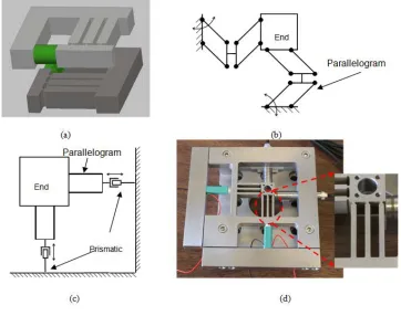
The high-bandwidth high-accuracy hybrid flexure-based nano-positioning modules can be applied to a variant of applications. A single hybrid flexure module can be used as a one degree-of-freedom nano-positioner. Such nano-positioning modules can also be configured to build a multi-degree-of-freedom positioner. By directly assembling two nano-positioning modules orthogonal to each other, a XY nano-positioning system can be built conveniently with low cost (Figure 9(a)).
Besides its direct usage in micro/nano-positioning, parallelogram flexure mechanisms are widely used as the basic building blocks for many low degree-of-freedom parallel kinematic stages, such as XY and XYZ micro/nano-positioning stages [12, 14, 15]. Figure 9(b, c) demonstrate two examples of parallel kinematic XY stage design.
In these designs, parallelogram mechanisms restrict all rotational degree-of-freedom of the end-effector, and they are the basic constituent units in these stage designs. The hybrid flexure modules can be applied as parallelogram mechanisms to achieve better structural bandwidth and positioning accuracy. Figure 9(d) shows a fabricated nano-positioning XY stage with the scheme from Figure 9(c) adopting the hybrid flexure mechanism.
Figure 9: (a) Two dimensional (XY) micro-positioning system. (b) Scheme of parallel kinematic XY
stage design using parallelogram mechanisms [15]. (c) Another XY stage design with prismatic joints
and parallelogram mechanisms [28]. (d) A high bandwidth XY stage implemented from scheme (c).
2.6 Conclusions
This chapter introduces the design of a new single degree-of-freedom bandwidth high-precision hybrid compliant-notch flexure-based nano-positioning module for high-throughput nano-manufacturing applications. Compared with widely used lumped-compliance mechanisms and distributed-compliance mechanisms, the hybrid flexure module adopts a hybrid flexure structure that is composed of compliant beams and notch-flexure hinges. This hybrid flexure design decouples the performance objectives for the structural bandwidth and parasitic accuracy that are correlated in the lumped-compliance flexure and distributed-compliance flexure. The parallelogram hybrid compliant-notch flexure enables simultaneously achieving a higher structural bandwidth and a smaller parasitic motion.
building blocks, and chapter 4 presents a specific application of this new design in micro/nano-manufacturing.
CHAPTER 3: Two degrees of freedom nano-positioning system
3.1 Introduction
Micro/nano-positioning systems with nanometer level resolution and accuracy are critically important for micro and nanotechnology. Nano-positioning stages are widely used in various applications, such as scanning probe microscope [2, 9], micro/nano-manipulation and manufacturing [3, 10, 11, 12, 13], and optical alignment [28]. The majority of the state-of-art nano-positioners utilize flexure-based structures, due to their smooth and friction-free motion and high durability without wear and deterioration. Piezoelectric actuators and high resolution displacement sensors are widely used with flexure-based mechanisms to obtain displacement with nanometer level resolution.
nano-scale manipulation and manufacturing. Closed-loop control is very important to obtain the required precision and accuracy. The achievable closed-loop bandwidth of a flexure-based nano-positioning system is generally limited by the resonant frequency of the nanopositioner due to the low damping characteristics of such flexure-based systems. A nano-positioning system with high natural frequency provides better performance capabilities for achieving a large bandwidth of the closed-loop control system.
The structural bandwidth (i.e. natural frequency) and accuracy are often contradictive performance requirements for a multiple degree-of-freedom flexure-based nano-positioner. The natural frequency of a flexure device can be improved through increasing the structural stiffness and decreasing the moving mass of the flexural structure. However, for the widely used flexure-based structures (e.g. compliant mechanisms and notch-flexure-hinges), simply scaling up the dimension of flexure components will bring severe side effect (e.g. parasitic rotary motion of the end-effector). As the stiffness of the flexure-based mechanism is increased for higher bandwidth, the parasitic motion of the system will increase as well, due to the undesired stress distribution and non-linear elastokinematic effects [25] over the mechanism when the dimension of the flexural components is scaled up. The high-bandwidth structures need to be designed carefully to minimize the parasitic motion for achieving high-bandwidth and high-accurate nano-positioners.
position control over the stage displacement. Ando and his team [30, 31] utilized stiff piezo-stack actuators to build XY positioning stages with high resonance frequency with limited motion range and operated these stages at open-loop mode. These stages were used in an atomic force microscopy to obtain real-time imaging of biomolecular processes. Schitter et. al. [32] developed a high-speed scanner based on compact flexures and actuated by piezo-stack actuators. Each axis is equipped with two actuators that are configured in a push-pull configuration. Leang et. al. [33] developed a high speed serial kinematic XY scanner for scanning probe microscope, in which the two axes are connected together in serial, in which one axis is carried by the other. As a result, one axis has a faster response than the other and the performances of the two axes are different from each other. Such configuration works better for line-by-line scanning applications in scanning probe microscopy than general purpose nano-positioning applications.
bandwidth cannot be simply obtained by scaling up the dimension of flexure components due to the requirement for high accuracy.
In this chapter, a high bandwidth XY nano-positioning system is designed and tested. The high-speed nano-positioner is expected to address applications such as high-throughput nanoscale metrology, imaging and manufacturing. The developed system is intended to achieve a high natural frequency while keeping the parasitic motion as low as possible.
A parallel kinematic mechanism is designed with two independent kinematic chains that connect the base to the end-effector in parallel. Each kinematic chain includes a prismatic joint that is actuated by a piezoelectric stack actuator and a parallelogram hybrid flexure mechanism. The parallelogram hybrid flexure mechanism is connected to the end-effector or the table. Each axis allows only planar translation with actuation in a single direction. The two kinematic chains are placed orthogonal to each other, thus spanning the XY plane. Kinematic and dynamic analyses show that the mechanical structure of the stage has decoupled motion in XY direction and has achieved high bandwidth.
(Proportional-Integral) controller is implemented for the stage and a closed-loop bandwidth of 2 kHz is obtained.
3.2 Mechanical design and kinematic analysis
Figure 10: (a) Mechanical structure of the XY nanopositioning system (b) Schematic representation
of the system (deformed system when x axis is actuated) (c, d) Equivalent linkage of the parallel
kinematics XY stage for the purpose of analysis at the nominal position and under actuation.
To implement this mechanism design, the prismatic joints are replaced by doubly-clamped beams as linear guides, and they are actuated by piezoelectric actuators. The doubly-clamped beams have large compliances in the actuation direction and a very large stiffness in the lateral direction. The parallelogram mechanism is implemented by a hybrid compliant-notch flexure (Figure 11), in which each linkage includes a compliant beam and a circular flexure hinge at the end of the beam. The parallel beams provide high structural stiffness to the studied system, while the flexure hinges help to relief the undesired stress concentration at the end of the beams and make the connector orient to the base very well. Compared with widely used lumped-compliance mechanisms (using notch-flexure-hinges) and distributed-compliance mechanisms (using compliant-flexure-beams), the hybrid flexure decouples the performance requirements for the structural bandwidth and parasitic accuracy that are correlated in the lumped-compliance mechanisms and distributed-compliance mechanisms [36]. The parallelogram hybrid flexural structure enables simultaneous achievement of a higher structural bandwidth and a smaller parasitic motion.
with a fixed length L. Here the motion of point T completely represents the motion of the end-effector, because it only undergoes pure translation.
For the kinematic analysis, the relationship between actuation displacement, which is linear displacement of two prismatic joints, and the displacement of the stage, needs to be found. In Figure 10, the coordinates of point O are chosen as the origin (0, 0), then the position where the kinematics chains connected to the base are A (0, d0+L), B (d0+L, 0). The nominal position for the table in this coordinate system is (d0+L, d0+L). After the prismatic joints are actuated to dx and dy, the coordinates at the end of the joints are A1 (dx, d0+L), B1 (d0+L, dy). The coordinates of the new position of the table T now can be solved as the length of the second joints remain the same. Let the position of the stage be (x,y), under the assumption of small displacement of the parallel beam, which is validated by micro/nano-positioning applications, we haveTB1 =TA1 =L, which satisfy the relationships given in equations 3.1
and 3.2.
(𝑥 − 𝑑 ) + (𝑦 − 𝑑 − 𝐿) = 𝐿 (3.1)
𝑦 − 𝑑 + (𝑥 − 𝑑 − 𝐿) = 𝐿 (3.2)
∆𝑑
∆𝑑 = 1 00 1
∆𝑥
∆𝑦 (3.3)
∆𝑥 ∆𝑦 = 𝐽
∆𝑑
∆𝑑 = 1 00 1
∆𝑑 ∆𝑑 (3.4) Here, 𝐽 = ⎣ ⎢ ⎢ ⎢ ⎡𝛿𝑥 𝛿𝑑 𝛿𝑥 𝛿𝑑 𝛿𝑦 𝛿𝑑 𝛿𝑦 𝛿𝑑 ⎦⎥ ⎥ ⎥ ⎤
= 1 00 1
(3.5)
The diagonal Jacobian matrix in equation 3.5 indicates a decoupled motion in X and Y directions around the operational point, when the device undergoes a small displacement relative to the overall dimensions of the stage (which is just the case for the nano-positioner). The effect of crosstalk between different axes (at the first order of approximation) is zero. One actuator will generate displacement in X direction and the other in the Y direction.
of table need to be derived. As shown in Figure 11, when an actuation effect is applied to the mechanism, a displacement of Δd is generated at the end-effector and also at the tip of the parallel beams. Since the end-effector is parallel to the base, the flexure hinges absorb the rotary deflection of the cantilever beam, thus the rotational angle of the hinge is equal to the deflection angle at the tip of the beam. When the deflection is small compared with the overall size of the mechanism, which is the case for micro/nano-positioning, the beam deflection angle and the rotary angle of the flexure hinges is given as follows:
∆𝜃 ≈3
2 ∆𝑑
𝐿
(3.6)
When one axis is actuated by a displacement of Δd, the parallelogram compliant structure on the other axis will also be displaced by Δdto decouple the motion between the two axes. Thus, we have
∆𝜃 ≈3
2 ∆𝑦
𝐿
(3.7)
∆𝜃 ≈3
2 ∆𝑥
𝐿
(3.8)
the hinges in the hybrid parallelogram flexure and the displacement of the end-effector can be linearized with Jacobian matrix, J1 and its inverse, J1-inv.
∆𝜃 ∆𝜃 = 𝐽 ∆𝑥∆𝑦 = 𝐽 . 𝐽 ∆𝑑 ∆𝑑 (3.9) where 𝐽 = ⎣ ⎢ ⎢ ⎢ ⎡𝛿𝜃 𝛿𝑑 𝛿𝜃 𝛿𝑑 𝛿𝜃 𝛿𝑑 𝛿𝜃 𝛿𝑑 ⎦⎥ ⎥ ⎥ ⎤ (3.10)
From differentiating Equations 3.7 and 3.8 with respect to dxand dy, inverse Jacobian matrix J1-inv is
given by:
𝐽 = 0
3 2𝐿 3
2𝐿 0
(3.11)
3.3 Structural and dynamic analysis
actuation force is applied in the middle of the doubly-clamped beam by piezoelectric actuators.
The overall workspace of the stage is defined by the stiffness of the mechanism and the actuation force that is applied by the piezoelectric actuator. The stiffness of the doubly-clamped beam is given by
𝐾 =192𝐸𝐼
𝐿 =
16𝐸𝑤𝑇 𝐿
(3.12)
Where I is the beam’s moment of inertia calculated from 𝐼 = , E is the Young’s Modulus of the structural material (i.e. stainless steel), w is the device thickness (8.76 mm), Tdb is the width of the doubly-clamped beam ( 5.1 mm), and Ldb is the length of the beam
(46.5 mm).
For the beams in the hybrid parallelogram flexure, since the flexure hinges absorb the rotary deflection at one end of the beams, the beams behave as free cantilever beams with a stiffness of:
𝑘 =𝐸𝑤𝑇
4𝐿
where T b is the beam width (1.68 mm), and Lb is the length of the compliant beam (19 mm). Since
multiple (3) beams are used as a parallelogram structure, the overall stiffness being n=3 is as follows:
𝐾 = 𝑛𝑘 = 𝑛𝐸𝑤𝑇𝑏
3
4𝐿𝑏3
(3.14)
One-dimensional circular flexure hinges are used in the stage design as rotary joints. The rotary
stiffness of the hinge is given by [27],
𝑘 =𝑇 𝜑 = 2𝐸𝑇 9𝜋 𝑡 𝑅 (3.15)
where t is the neck thickness of the flexure hinge (0.5 mm), R is the radius of a flexure hinge at the neck (0.5 mm), and T is the height of the flexure hinge or the device thickness (8.76 mm). In the parallelogram mechanism, when the end-effector of the mechanism is actuated, all the flexure hinges undergo the same deflection, thus the rotary stiffness from the flexure hinges is Kz = nkz .
When the device is actuated, the work done by the actuator is balanced by the energy stored in the hinges and the beams. From the principle of virtual work:
1
2𝐹 ∆𝑑 +
1
2𝐹 ∆𝑑 =
1
2𝐾 (∆𝑑 ) +
1
2𝐾 ∆𝑑 +
1
2𝐾 (∆𝑥) +
1
2𝐾 (∆𝑦) +
1
2𝐾 (∆𝜃 ) +
1
2𝐾 ∆𝜃
This equation can be expressed in matrix form:
𝐹 ∆𝑑
𝐹 ∆𝑑 = 𝐾0 𝐾0 +
𝐾 0
0 𝐾 +
𝐾 0
0 𝐾 (𝐽 . 𝐽)
∆𝑑 ∆𝑑
(3.17)
where Fxand Fyare actuation force for X and Y axes. Assuming only one axis (X) is actuated, we
have
2
2 2 3 2
2
x x db x b x z x
F d K d K d K d
L
⎛ ⎞
Δ = Δ + Δ + ⎜ ⎟ Δ
⎝ ⎠ , thus 2.25 2
x x z db b F d K K K L Δ =
+ + . The
overall stiffness of the system is given by
𝐾 = 𝐹
∆𝑑 = 𝐾 + 𝐾 + 2.25
𝐾 𝐿
(3.18)
From this specific design, the total stiffness is K = 39.5E6 N/m, while the doubly-clamped beam contributes more than 95% of the total stiffness.
compliant beams and hinges. For a flexure hinge, the maximum bending torque that can be applied to is:
𝑀 =2𝜎 𝐼
𝑡
(3.19)
where Imin = wt3/12, which is the smallest moment of inertia of the flexure hinge about the
rotation axis; σp is the stress limit. The motion range limit of a flexure hinge αz−max and the
maximum displacement of the mechanism Δdmaxcorresponding to the maximum bending torque are:
𝛼 = 𝑀 𝐶 (3.20)
∆𝑑 =2
3𝛼 𝐿
(3.21)
For the parallel cantilever beam, the maximum stress occurs at the fixed end with the maximum stress to be 𝜎 = 𝜎 = . The maximum displacement that the beam undergoes before failure is:
∆𝑑 = 2𝜎 𝐿
3𝐸𝑇
For the double-clamped beam, the maximum stress occurs at the fixed end and the middle of the beam with the maximum stress to be 𝜎 = 𝜎 = . The maximum displacement that the beam undergoes before failure is:
∆𝑑 = 𝜎 𝐿
12𝐸𝑇
(3.23)
The maximum achievable displacement of the device is defined by
max max max
min(Δd −z,Δd −b,Δd −db). For this specific design, stainless steel is used to fabricate the nano-positioning stage. The rotation limit of the rotary hinge is 𝛼 =
±0.0029 𝑟𝑎𝑑𝑖𝑎𝑛𝑠, which indicates a maximum motion range of 36 microns. The maximum
motion from the parallel cantilever beams and double-clamped beams are 171 microns and 51 microns respectively. It is clear that the maximum stress concentration is located in the flexure hinges, and that the maximum displacement is bounded by their behavior.
𝑑 𝑑𝑡 𝜕𝑇 𝜕𝑞̇ − 𝜕𝑇 𝜕𝑞 + 𝜕𝑉
𝜕𝑞 = 𝑄 , 𝑖 = 1,2, . . . 𝑁
(3.24)
where, T represents the total kinetic energy of the system, V is the potential energy which includes both strain energy and the potential of any conservative external forces, where qi
represent linearly independent generalized coordinates, Qi represents generalized
non-conservative forces, and N is the number of generalized coordinates, which is also equal to the number of DOF of a system (two for this designed stage). Assuming the hinges as perfect springs, and without considering any non-conservative forces, a multiple degree-of-freedom harmonic oscillator is expected. The stage has 2 generalized coordinates which we will conveniently use as the axes directions x and y of the table (that undergoes no rotations). For free vibrations of the stage, since there are no external or dissipative forces, Qi = 0. From
the kinematics of the stage, it is given that Δ = Δp J q where, Δ = Δ Δp
[
x y,]
T and, T
x y
q ⎡ d d ⎤
Δ = Δ⎣ Δ ⎦ .
effective mass with a numerical value 33/140 from [36]. The total kinetic energy in the system is given by:
𝑇 = 𝑇 + 𝑇 + 𝑇 = 1
2[𝑣 𝑣 ]𝑀
𝑣
𝑣 =12[𝑣 𝑣 ] 𝑀0 𝑀0
𝑣
𝑣 (3.25)
where vx = Δx v&, y = Δy&
Here M is the mass distribution matrix with
𝑀 = 𝑚 , + 𝑀 , + 𝑚 , + 𝑀 = 𝑐𝑀 + (1 + 𝑐)𝑀 + 𝑀 (3.26)
and
𝑀 = 𝑚 , + 𝑀 , + 𝑚 , + 𝑀 = 𝑐𝑀 + (1 + 𝑐)𝑀 + 𝑀 (3.27)
The potential energy in the system is given by the energy stored as elastic deformation of the hinges and compliant beams. The strain energy of a flexure hinge deformed by an angle of
Δθ is 1 2
2
V = kΔθ , and in a compliant beam deformed by a displacement Δd is 1 2
2
V = k dΔ .
𝑉 =1
2𝐾 [∆𝑑 ∆𝑑 ].
∆𝑑 ∆𝑑 =
1
2𝐾 [∆𝑥 ∆𝑦]. [𝐽 𝐽 ]
∆𝑥
∆𝑦 (3.28)
The energy stored in the parallelogram beams when the table has moved by Δ = Δ Δp
[
x y,]
is given by:𝑉 =1
2𝐾 [∆𝑥 ∆𝑦].
∆𝑥
∆𝑦 (3.29)
and the energy stored in the flexural hinges is:
𝑉 =1
2𝐾 [∆𝜃 ∆𝜃 ].
∆𝜃 ∆𝜃 =
1
2𝐾 [∆𝑥 ∆𝑦]. [𝐽 𝐽 ].
∆𝑥
∆𝑦 (3.30)
Therefore the total potential energy in the system is given by:
𝑉 = 𝑉 + 𝑉 + 𝑉 =1
2[∆𝑥 ∆𝑦]. [𝐾 𝐽 𝐽 + 𝐾 𝐽 𝐽 + 𝐾 𝐼].
∆𝑥
∆𝑦 (3.31)
𝑀 0
0 𝑀 ∆𝑥̈∆𝑦̈ + [𝐾 𝐽 𝐽 + 𝐾 𝐽 𝐽 + 𝐾 𝐼]. ∆𝑥∆𝑦 = 0 𝑜𝑟 (3.32)
𝑀0 𝑀0 ∆𝑥̈∆𝑦̈ + 𝐾. ∆𝑥∆𝑦 = 0
Thus, it is a 2-DOF harmonic oscillator. The eigenvectors of 1
M K− will give the modal
directions for the system and the corresponding eigenvalues λi, give the corresponding modal
frequencies 1
2
i i
f λ
π
= . Based on the design of the compliant flexural components and the
numerical values for the different matrices, the modal directions along X and Y directions and a main resonant frequency of 7130 Hz are found.
3.4 Design Considerations for a high-bandwidth stage
The kinematic scheme presented in the previous section had to be adapted for physical realization of a
flexure-based, parallel kinematic nano-positioning stage. The monolithic stage structure that includes
a doubly-clamped beam and a parallelogram hybrid flexure module for each axis is fabricated on a
wire-EDM (Electrical Discharge Machining) machine. To achieve a high-bandwidth, the mechanical
structure needs to have a large stiffness and large natural frequency. Besides the required high overall
mechanical stiffness, the stiffness needs to be distributed to different compliant components properly
to achieve the performance requirements on bandwidth and accuracy. The kinematic analysis assumes
that the doubly-clamped beam is a linear guide and provides linear displacement. However, this
of the parallelogram flexure mechanism. Otherwise the parallelogram flexure mechanisms that
connect the end-effector to the two doubly-clamped beams cannot completely decouple the behavior
between the two kinematic chains. As results, the doubly-clamped beams are designed to have a large
stiffness while the parallelogram flexure mechanisms are designed to have a large compliance to
decouple the two axes displacements. On the other hand, the parallelogram flexure mechanisms still
need to have a minimum stiffness to support the end-effector and make sure the local vibration modes
will not deteriorate the overall natural frequency of the device.
maximum current of 1A and output voltage of -30V to 150V are selected to drive the actuator.
Capacitive sensors (Probe 2805 and Gauging Module 8810 by ADE Technologies, range +/-5μm, bandwidth 10 kHz with analog output of +/-10 V) are used as displacement sensors to directly sense the motion of the end-effector. The targets for the capacitive sensors are provided by a cubical metal block with two polished orthogonal surfaces, mounted on to the bottom of the end-effector. The sensors are fixed to the base to measure displacement by sensing the change in capacitance due to the motion of a metal target block on the end-effector. As non-contact sensors, they do not contribute to load, friction or wear. Further, the setup and calibration are relatively easy and the resolution obtained is significantly higher than most other types of displacement sensors.
The stage assembly is constructed by mounting the target block, capacitive probes and piezoelectric actuators on to the monolithic flexure structure. The assembled device is shown Figure 10 (a).
maximum force must also be considered to guarantee that it is capable of providing the required actuation force for the specific designed system.
3.5 Finite Elements Analysis and Results
In this section, FEM (Finite Element Method) analysis is performed to verify the design objectives of this high-bandwidth XY nano-positioning system. The FEM simulation is performed using COMSOL software. The global stiffness, required actuation force, and the maximum achievable displacement of the system, as well as its stress distribution are studied using static analysis. Then, the dynamic behavior of the device, such as vibration modes and their corresponding resonant frequencies are obtained from the dynamic analysis. The finite element model of the designed mechanism has the same boundary conditions to the actual assembly where all the unmovable parts are full constrained. The actuation force is applied to the middle points of the double-clamped beam. The material of the mechanism is set to be stainless steel with Young’s modulus E = 205 GPa and Poisson’s ratio = 0.28.
Figure 12: Stage displacement under different actuation force.
The results fit into a line very well, which indicates the good linearity of the stage response. The slope of the fitted line (i.e. stiffness of the mechanism) is 4.13 E7 N/m, which is close to the theoretic analysis.
Figure 13: (a) Stress distribution of the deformed mechanism with deformation magnified by 100. (b)
Stress distribution around the flexure hinges.
Figure 14: Vibration modes and their corresponding frequencies.
occur when the parallelogram hybrid flexures bend in the same directions or in different directions.
The other four modes are related to the lateral dynamics of the parallelogram hybrid flexure mechanisms, and they are not directly related to the actuation behavior. These local vibration modes correspond to a mode that is roughly 6 times stiffer than those associated with the desired XY motions. This is attributed to the parallel kinematics XY stage design which besides producing a relatively high natural frequency associated with the dominant modal directions (the desired translational DOF in XY plane), also provides for large separation between the modes associated with the desired motion and other high-order modes. The dominant model has a resonant frequency of 7411 Hz, which verify the theoretical analysis, and provide high potential for fast operation and high-throughput.
Even though micro/nano-manufacturing applications are not associated with heavy load, there will be some loads in Z axis from the sample and sample holder’s weight and the force from the manufacturing processes. The structure is desired to have a large stiffness in Z-direction and small out-of-plane motion. As part of the FEM analysis, the out-of-plane stiffness is estimated by applying a load in Z-direction to the end-effector of the mechanisms, and recording its Z-displacement.
withstand the manufacturing process without producing considerable displacements in this direction.
Figure 15: Out of plane displacement under Z load.
3.6 Experimental results
cross-coupling comes from the mechanism design that decouples the motion in the X and Y directions.
Figure 16: (a, c) Experimentally measured static displacement with respect to actuation voltage for
one axis. (b, d) Cross-coupled displacement from the other axis.
the hysteresis from the piezoelectric actuators can be observed from the open-loop step response from Figure 16 (a, b)). The total workspace of the stage is about 15x15microns in the XY directions.
Resolution is an important performance for a nano-positioning system. In this flexure-based system, reference signals in XY directions are directly controlled, there is no error from kinematic interpolation. The resolution is primarily restricted by noise. Due to the low damping of the mechanical structure, this high frequency noise will vibrate the stage and deteriorate the positioning resolution.
Considering the sensor’s accuracy as the best possible resolution of the system, the achievable resolution is limited by many other factors, such as environmental disturbance and electronic noise.
Figure 18: Noise histogram of steady state sensor measurements.
For this particular system, Figure 18 demonstrates a noise histogram of the steady state output from the position sensors. The standard deviation of the output signal is 0.77 nm when the system is actuated and hold at a command position, which indicates a nanometer level resolution.
The two axes have similar dynamic response with the dominant resonant peak at around 8.9 kHz. This experimental value is larger than the results from the theoretic analysis and finite element analysis. These discrepancies can be explained by approximations made in the effective mass in the system, and dimensional errors during manufacturing.
Figure 19: Frequency response of the nanopositioner. (a) From X actuator to X displacement. (b) X
The stage has an almost flat magnitude response up to 6 kHz in the directly actuated axes, which provide better potential for closed-loop control design. The cross-talks between the two axes (Y-X and X-Y response) are insignificant at most of the frequency range. The DC gain of the off-diagonal response differs from the gain of the diagonal frequency response by 30 to 40db. Such cross-coupling effect can be compensated by the closed-loop control.
To construct a closed-loop system, A DSP (digital signal processing) based motion controller is used to receive displacement feedback from capacitive sensors, calculate the control out and send it to the amplifier. A high resolution (16 bits) A/D converter is used to translate the analog voltage positional signal to digital signals used by the controller.
Since the sensitivity of the capacitance sensor is 2.5μm/volt and the maximum value of the 16 bit digital signal is 10 volts, the resolution from the ADC is about 0.76 nm, which is the best resolution of the control loop. A piezo amplifier with a magnification factor of 20 is used to receive command signals from the controller and provide amplified voltage to drive the piezoelectric actuators. To close the position loop, a PI (Proportional-Integral) controller was implemented on the controller. The PI controller can obtain a larger than 1 kHz closed-loop bandwidth. Figure 20 shows the closed-closed-loop step response of two axes.
Figure 20: Closed-loop step response in X (left) and Y (right) directions.
With a mechanical design with higher resonant frequency, even a simple PI controller can gain a very high-closed loop bandwidth. Figure 21 shows the control result for stepwise motion of the stage using the PI controller. The step size was 1 µm.
Clearly, the closed-loop control provides a linear and repeatable motion, compared with open-loop operation as shown in Figure 16 (a,b), in which the nonlinear hysteresis effect from the piezoelectric actuators can be easily observed.
Figure 21: Closed-loop stepwise motion.
This resolution is comparable to the open-loop result, and a nanometer level control resolution is obtained for high precision and high accuracy applications.
3.7 Conclusions
is expected to address applications such as high-throughput nanoscale metrology, imaging and manufacturing.
CHAPTER 4: Micro-milling using the designed hybrid two DOF nano-positioning stage
4.1 Introduction
Micro-manufacturing is one of the most important and active fields of study due to its broad applications in the modern industry. Gyroscopes and accelerometer for aerospace and automotive industries, biosensors and micro-needles for medical and biomedical companies, solar cells and data storages for telecommunications and information peripherals, and chemical and bio-sensors for environmental monitoring are just a few examples of the many applications that micro-manufacturing has in modern industry.
Micro-manufacturing was originated from microelectronics industry, and currently it has extended to as many and diverse applications as semiconductor manufacturing, MEMS (micro-electro-mechanical systems), nanotechnology, and biomedical applications, among others. There are many micro-manufacturing techniques that are required for these industries, such as lithography, additive processes (deposition, doping and oxidation), subtractive processes (dry and wet etching) and surface micro-machining (bulk and patterning).
such as cutting, sandblasting, ultrasonic machining and grinding can be listed as part of this group. From this group, cutting is the one that presents the best geometric correlation between the tool path and the desired features in the machined surface due to the fact that in this process, there is physical contact between a single point of the tool and the work piece.
Many alternatives have been proposed to improve these micro cutting processes. The main objectives are to decrease the size of the smallest achievable feature that can be machined, as well as better surface finish, good accuracy and high efficiency to reduce costs. The first approach that can be found in the literature is the miniaturization of the conventional scale milling process. This approach is limited by the minimum size of the micro-milling tool, especially due to the brittle characteristics of the required materials, and the extremely fast required spindle speed. Features of around 50 um in size have been achieved using hard metals micro-milling tools in brass and stainless steel [42]. Micro-milling machines with multiple degrees of freedom have also been presented as an alternative for milling miniaturization [43]. Attempts to measure and optimize the required parameters to obtain the desired surface finish and accuracy have been previously developed as shown in [44, 45].
CNC cutting machine that generates a circular path to rotate the tool instead of the spindle, and also generate the required displacements to create the desired features. However, these alternatives have some problems.
In the first case, the tool size and spindle speed are the limitations. For the second approach, due to the fact that it is based on the scratching of the surface, and not on the continuous cutting that is characteristic in conventional scale machining, they present issues related to surface quality and tool life prediction. The achievable feature shapes are also limited in this approach due to the one directional nature of the process, which lack of the flexibility that conventional methods present in feature shapes. The productivity and effectiveness of the last proposed alternative [47] is limited mainly for the achievable speed in the circular path tool displacement.
technique is capable of achieving is also presented. Finally, a comparison between the previous achievements and this new approach’s characteristics is presented to justify its application.
4.2 Methodology
Conventional scale milling requires a cutting tool, a sample, and a machine that provides the necessary relative displacement between the cutting tool and the sample. Usually this displacement is divided in two different motions. The first one consists of the tool rotation that provides the cutting force, and the second is the one provided by the positioning system that moves the sample to create the desired features.
for the automation platform, and the rotation like displacement is controlled through varying the voltage and phase of the sinusoidal signals applied to the two piezoelectric actuators attached to each axis of the nano-positioning system.
In this way, the sample can be moved as desired using the controller to create the required features. The micropositioning system provides a circular path relative displacement between the sample and the tool, so the tip and nano-positioning system assembly acts as a single tooth micro-milling tool with a minimum diameter of a few microns (depending on the applied voltage and tip diameter) mounted on a spindle that can achieve rotation speeds as high as 360.000 rpm. This approach is similar to fly cutting at conventional scales, but uses the nano-positioning stage instead of the conventional rotational spindle to generate the sample-tool relative motion. This configuration allows the achievement of features between several nanometers to a few microns with good accuracy, high efficiency and relatively low cost.
4.3 Set up and practical considerations
1.6). Then, the sample nano-positioning assembly is attached to the automation platform using another set of screws. Finally, the zero set up is performed using a NAVATAR I-6265 zoom lens attached to a digital Unibrain microscopic video camera to visually approach the tip, and a multimeter to detect the final contact with the sample. A picture of the assembled system is presented in Figure 23.
Figure 23: Set up for the proposed micro machining process.
any circumstances the tip radius. As it was told, the used tip radius is around 500 nm, so the approaching process must be made with extremely carefulness to avoid damaging the tip. For this reason, this approaching process is divided in three steps.
The first step is similar to the one used to localize the tip in the X and Y axes, it is, a visual approach until the tool is safely close to the sample. When the tip is as close as possible to the sample using this approach, the digital video camera with a magnification factor of 393 X is used to continue the approaching process. In this step, an extremely low approaching speed (around 100 nm/sec) is used to assure the integrity of the tip. This is done using the CNC control. The final step is a step by step approaching process using an even slower speed (50 nm/sec) and a 50 nm step. The multimeter is then used to detect the tool-sample contact through measuring the electrical resistance between the sample and the tip. When the tip touches the sample, this resistance is close to zero, so the step by step process is continued until the reading in the multimeter is close to zero. Through this process, a maximum tip-sample engagement of less than 50 nm is guaranteed for the first pass. Despite of this fact, because of the lack of the sample total flatness, sometimes the first pass can have more than 500 nm of engagement, producing damage to the tip and future problems to the surface finish and accuracy of the whole process.
is in the air but very close to the sample). Then, if there is a higher point in that surface, it will be machined before the others, thus ensuring a maximum engagement equal to the chosen Z step, which must be less than the previous mentioned tip radius. Using this approach, the tip integrity and the best possible surface finish are ensured.
To provide the necessary tool-sample displacement, a National Instruments data acquisition system (NI USB-6259 M SERIES) connected to a conventional PC is used. Using this equipment, two equal magnitude but different phase sinusoidal signals are sent through two piezoelectric amplifiers as actuation signal to the two axes piezoelectric actuators of the system. Varying the voltage and frequency, the circular path diameter and the angular velocity are changed and can be successfully controlled. The same system allows the user to control the resulting motion using capacitance sensor. In this way, changes in tool path can be recorded and further correction can be made to optimize the system’s behavior.
4.4 Machining variables calculations
can be controlled in this new technique, and its variation is equivalent to a different tool diameter in conventional scale machining through the relation expressed in equation 4.1.
𝑇 = 𝑉 + 𝑑 (4.1)
where Td is the virtual tool diameter and dt is the diameter of the used tip.
The depth of cut is also controlled through the Z displacement of the tool, as in a conventional milling process.
These parameters can be controlled using the basic set up in the CNC G-CODE programs and the vibration parameters (signals’ frequency, phase and amplitude) of the nano-positioning system. Spindle speed is directly related with vibration frequency in kHz. This vibration frequency (𝑉 ) in combination with the linear speed, that in this case defines the feed rate in mm/sec, determine the feed per tooth in um/rev as follows:
𝐹 =𝑓𝑒𝑒𝑑 𝑟𝑎𝑡𝑒
𝑉
(4.2)
This equation is valid because the system behaves as a single tooth tool milling process. The feed per tooth must be kept under the tip radius value to ensure good results.
𝑈𝑅 =3𝑟𝜋𝐹 4
(4.3)
where r is defined as the vibration amplitude (A) plus the tip radius. The parameters’ combinations to obtain optimal results are material dependant. In the next section, a summary of experiments using aluminum samples (5052 alloy) are presented and the results are analyzed for further recommendations.
4.5 Experiments results
The first set of experiments was devoted to obtain satisfactory microscopic visual results in surface quality. The final judgments were performed based on digital pictures taken using an Olympus BHM metallurgical microscope (400 X maximum magnification factor) with a Paxcam digital microscope camera connected to a PC. To do so, Picoprobe ST-20-05 tungsten tips with diameter equal to 1 um were used as cutting tools and square 5052 aluminum pieces of 1 cm size were used as samples. Due to the specific aluminum alloy characteristics, the general propose Tap Magic cutting fluid was added to the process based on literature recommendations [49]. The machining parameters were then changed systematically to compare the obtained results. The different parameter combinations used for these visual surface quality tests are summarized in Table 2: Parameters combinations for visual surface quality tests..
nano-positioning stage motion. It is, the maximum voltage was not enough to produce the required amplitude at those frequencies.
Table 2: Parameters combinations for visual surface quality tests.
Parameter Initial value Final Value Increment
Vibration frequency (kHz) 0.50 6.00 0.50 Feed per tooth (um/rev) 0.10 0.50 0.05 Circular path diameter (um) 2.00 4.00 0.50
The combinations involving 0.5 kHz vibration frequency and feed per tooth less than 0.25 did not produced good results because these speed-feed rate combinations were not enough to form a chip during the cutting process, producing then the base material to melt and the surface quality to degrade.