Efficiency Comparison of Diversity
Techniques in FSO links for Fading mitigation
using EDFA and APD
Rekha Reghunadh1, Lakshmy G.B2
PG Scholar, Dept. of ECE, TKM Institute of Technology, Kollam, Kerala, India1
Asst. Professor, Dept. of ECE, TKM Institute of Technology, Kollam, Kerala, India2
ABSTRACT: Free Space Optics technology is the advanced wireless communication system that provides higher bandwidth with a higher data rate transmission over higher link range. Due to propagation in free space, the signal gets attenuated and loses information until it reaches the receiver end. These factors affecting the communication in FSO technology generates the need of using amplifiers and sophisticated photodetectors in the link. The performance of amplifiers like EDFA and SOA and photodetectors like PIN and APD are analyzed using OptiSystem.12 software and the best pair of optical amplifier and photodetector to yield better Q factor, eye height, received signal power and minimum BER is selected to analyze weather conditions with diversity techniques.
KEYWORDS: Optical amplifiers; Photodetectors; Atmospheric turbulences; Diversity
I. INTRODUCTION
Free space optical (FSO) communication uses visible or infrared (IR) wavelengths to broadcast high-speed data wirelessly through the atmospheric channel. FSO technology is based on connectivity between FSO-based optical wireless units, consisting of a high-power optical source (i.e. LASER), and a lens that transmits light through the atmosphere to another lens receiving the information. The receiving lens connects to a high-sensitivity receiver via optical fiber. Free Space Optics (FSO) Technology is the advanced wireless communication system that provides higher bandwidth with a higher data rate transmission over higher link range. The free space optical communication has only difference that this system ignores using solids such as optical fiber cable or optical transmission line as transmission medium.
The performance of FSO communications is mainly dependent on the unpredictable atmospheric channel such as fog, smoke and temperature dependent turbulence.Most significant is the fact that rain, dust, snow, fog, or smog can block the transmission path and shut down the network. Attenuation under clear air conditions is mainly due to the absorption by gaseous molecules. Atmospheric absorption at specific optical wavelengths results from the interaction between photons and atoms or molecules which leads to the absorption of the incident photon and an elevation of the temperature. Molecular absorption is a wavelength-selective phenomenon which results in atmospheric transmission windows and atmospheric absorbing regions. All these degrade the performance of free space optical communication system.
II.LITERATURESURVEY
A. General Background :
Free Space Optical (FSO) communication is an agelong technology in which the transmission of information is by optical radiation through the atmosphere from one pointto the other. The first optical communication in an unguided channel was the Photophoneexperiment by Alexander Graham Bell in 1880. In his experiment, Bell modulated theSun radiation with voice signal and transmitted it over a distance of about 200 metres.The receiver was made of a parabolic mirror with a selenium cell at its focal point. However, the experiment did not go very well because of inaccuracy of the devices used and the intermittent nature of the sun radiation. FSO has also been heavily researched for deep space applications by NASA (National Aeronautics and Space Administration) and ESA (European Space Agency) with programmes such as the then Mars Laser Communication Demonstration (MLCD) and the Semiconductor-laser Inter-satellite Link Experiment (SILEX) respectively.
B. Challenges faced by FSO communication :
FSO provides good solutions for broad band networks, especially in geographical areas where optical fiber deployment is not feasible but there are some performance limitations. The most dominant factors are atmospheric conditions such as fog, dust, snow,rain etc.
i. Rain attenuation : Rain is the highest attenuation factor in environment for light,so it effects the FSO link also. Rain can reduce visibility to much higher intensity. Rain intensity factor is capable of attenuating laser power andeffect the FSO system. The visibility of FSO system depends upon the quantity of the rain.The attenuation due torain is described by :
= 1.076 .
where R represents the rainfall rate. The increase in rainfall rate causes linear increase in attenuation and raindrop size also increases with rainfall rate. The scattering due to rain is non-selective as attenuation coefficient has no dependence on laser wavelength.
ii. Fog attenuation : Fog is a visible mass of water droplets which scatter incident light and reduces visibility. Fog is the most critical attenuation factor among all atmospheric attenuations. Mie scattering is used to calculate attenuation. The specific attenuation is calculated from Kruse model by :
( | )( | )
where V is the visibility in km and q is the particle size distribution. Low visibilities increases atmospheric attenuation and reduce the availability of optical signals from free space.
iii. Haze attenuation : Haze is an atmospheric phenomenon where dust, smoke and other dry particles obscure the clarity of the sky. It results in more particles to stay longer in atmosphere as compared to rain and hence presents more serious degradation on FSO performance.
Here also Kim and Kruse model is used to calculate specific attenuation as :
= (3.91| )( |550)
C. Diversity Technique in FSO :
Diversity is one of the methods to provide high quality services by sending several copies of the same signal. It gives reliability to the transmission. Diversity techniquesare effective when the branches considered are assumed to be independently faded. Spatial diversity is the major type of diversity technique where in one path signal undergoes a fade and in another path may have strong signal. As there are more than one path the average SNR at the receiver gets improved. The use of multiple antennas allows to exploit spatial dimensions of channel and to provide reliability by transmitting same signal through many new degrees of freedom.
III.PROPOSEDMETHODOLOGY
A. FSO System Model :
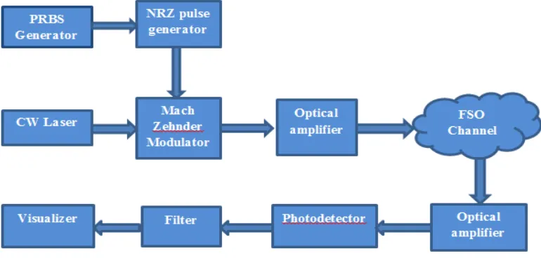
FSO system consists of mainly three sections namely transmitter, atmosphere as channel and a receiver which is shown in figure 1.The transmitter section includes the sequence generator which generates the binary input. It is then fed to LED/laser diodes driver circuit which helps to convert binary input to light signals with the help of Mach Zehnder modulators. This light signals are then directly send to the channel ie, atmosphere. FSO technology is based on connectivity between FSO-based optical wireless units, consisting of a high-power optical source (i.e. LASER), and a lens that transmits light through the atmosphere to another lens receiving the information. The receiving lens connects to a high-sensitivity receiver via optical fiber. Due to propagation in free space, the signal gets attenuated and loses information until it reaches the receiver. These factors affecting the communication in FSO technology generates the need of using amplifiers and sophisticated photodetectors in the link. After propagation through the atmosphere it is converted to electrical signals by the photodiodes in the receiver section. These signals are converted back to binary signals through signal processing. The general free space optical communication system is shown in figure 1 below.
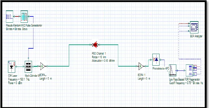
0.43 dB/km, 4.3 dB/km and 43 dB/km respectively [7]. Initially, the attenuation value is set as 0.43 dB/km (clear). The optical signals from the FSO channel are received by photodetector APD. A low pass Bessel filter is used to filter the signal from noise [1]. This simulations uses three visualizers namely optical power meter, optical spectrum analyser and BER analyzer. Optical spectrum analyzers provide the facility to analyze the optical spectrum. Optical power meters gives the power received in both dBm and Watts. BER analyzer automatically calculates the BER value, Q factor and display eye diagram.
B. FSO link distance and bit rate variation with various optical amplifiers and photodetectors :
Due to propagation in free space, the signal gets attenuated and loses information until it reaches the receiver end. These factors affecting the communication in FSO technology generates the need of using amplifiers and sophisticated photodetectors in the link. The use of amplifiers mainly EDFA and Travelling wave SOA are analyzed, which not only improves the signal quality but also increases the range of communication. At the receiver side the performance of photodetectors like PIN and APD are analyzed using optiSystem 12 software. From the analysis the best pair of optical amplifier and photodetector to yield better Q factor, eye height, received signal power and minimum BER is selected as EDFA-APD and is used for a robust FSO link simulation. Simulations of both 1 TX/1 RX FSO system with a power of 10 dBm, range of 10 km and bit rate of 2.5 Gbps are analyzed for different combinations of amplifiers and photodetectors.
Wavelength 1550nm Input laser power 5 – 25 dBm Attenuation 0.43 (clear) FSO length .5 – 10 km Transmitter aperture diameter 10cm Receiver aperture diameter 25 cm Beam divergence 2 mrad
C. Diversity technique in Free Space Optics system :
Figure 2: FSO system with spatial diversity
IV. SIMULATIONRESULTS
The OptiSystem software is developed by Optiwave to perform complex optical communication simulation. It provides an easy user interface which is common to many other electrical engineering tools. The OptiSystem 12 software is suitable to be used to model and simulate fiber optic system, free space optic system and also OWC system.
Figure3 : Simulation diagram of general FSO system
in graph below.The figure 4 represents the graphical analysis when bit rate and link distance is varied. The better Q-factor value is obtained for EDFA-APD pair compared to others.
Figure 4 : Link distance and bitrate variations with Q-factor
Diversity is one of the methods to provide high quality services by sending several copies of the same signal.It gives reliability to the transmission. Spatial diversity is oneof the possibilities of including diversity based on theavailability of multiple antennas at the transmitter or thereceiver. It is possible to linearly increase the throughput ofthe channel with every pair of antennas added to the system.The use of multiple antennas allows to exploit the spatialdimension of the wireless channel and to provide reliabilityby simultaneously transmitting the same signal through thenew degrees of freedom provided by this spatial dimension.Space diversity is called transmit diversity if multipletransmit antennas are used for transmission purpose andreceive diversity if multiple receive antennas are used forreceiving purpose.
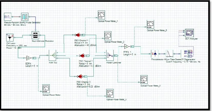
In the simulation layout shown in Figure 5, instead of one FSO channel, three channels are used. Fork is used for duplicating the input beam to all the channels. Output port of fork is set as 4, since four channels are considered. At the receiver end, the optical signals from these channels are combined with the help of a power combiner having 3 input ports. At the transmitter side power is measured and after each channel output powers are measured. Final received power is analysed to determine the best channel path for transmission.
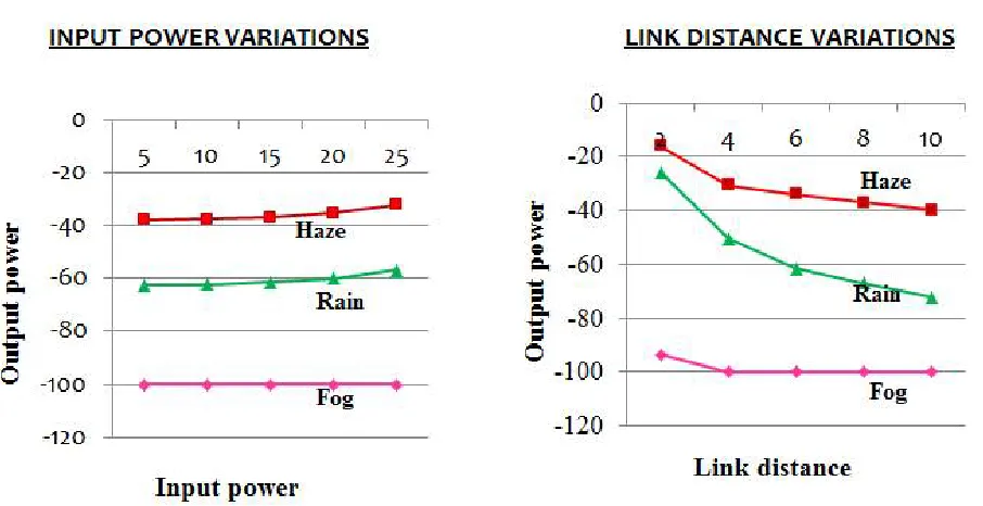
Figure 6 : Input power and link distance variation for different weather conditions
The figure 6 represents the graphical variations of output power for three different weather conditions (rain, haze, fog). The analysis is done by varying input power and link distance. Out of the three weather conditions, haze condition provides a better result than rain and fog conditions. Fog condition provides severe attenuation to the optical signal transmitted.
V. CONCLUSION
Free Space Optics is a promising communication technology in the near future. Due to the atmosphericdisturbances, there is distortion of signals at the receiver. Incorporation of sophisticated optical amplifier EDFA and highly sensitive photodetector APD improved the system performance. Also by using new techniques it is possible to reduce theatmospheric effects on the optical signal. Incorporation ofspatial diversity in the FSO system increased the efficiency ofsystems under different disturbances, out of 3 conditions (rain, fog and haze) considered, the haze channel performed better than other FSO paths.
REFERENCES
4. Amit Gupta, Shaina, “Mitigating the effects of attenuation in FSO link using EDFA”, International Journal of Scientific Engineering and Applied Science(IJSEAS), Vol.1, Issue-8, November 2014.
5. Zeenat Afroze, Farhana Hossain, “Eliminating the effect of Fog attenuation on FSO link by multiple Tx/Rx system with TWSOA”, IEEE , December 2014.
6. Nur Haedzerin Md Noor, Wajdi Al-Khateeb, A.W. Naji, “ExperimentalEvaluation of Multiple Transmitters/Receivers on Free Space Optics Link”, IEEE Student conference on Research and Development, 2011.
7. AditiMalik and Preeti Singh, “Free Space Optics: Current Applications and Future Challenges”, International Journal of Optics volume 3, Article ID 945483, 7 pages, 2015.
8. Somanath Pradhan, P.K Sahu, Rajat Kumar Giri, “Intersatellite optical wireless communication design using Diversity techniques”, International conference on microwave, IEEE, vol.2, issue 8,December 2015.
9. Nitika Sachdeva, Deepak Sharma, “Diversity: A Fading Reduction Technique”, International Journal of Advanced Research in Computer Science and Software Engineering, vol 2, Issue 6, June 2012.
10. Jan Vitásek, Jan Látal, Stanislav Hejduk, Jiří Bocheza, Petr Koudelka, Jan Skapa,Petr Šiška, and Vladimír Vašinek, Atmospheric Turbulences in Free SpaceOptics Channel “, IEEE, 2011.
11. Pravin W. Raut, Dr. S.L. Badjate, “Diversity Techniques for WirelessCommunication”, International Journal of Advanced Research in Engineering and Technology, Volume 4, 2013.
BIOGRAPHY
Rekha Reghunadh received her B.Tech degree in Electronics and Communication Engineering from Cochin University of Science and Technology in 2015. She is currently pursuing second year M.Tech in Optoelectronics and Communication Engineering at TKM Institute of Technology, Kollam, Kerala, India.