University of Windsor University of Windsor
Scholarship at UWindsor
Scholarship at UWindsor
Electronic Theses and Dissertations Theses, Dissertations, and Major Papers
2012
Temperature measurement and thermal control of die casting
Temperature measurement and thermal control of die casting
processes using CCD cameras
processes using CCD cameras
Davor Srsen
University of Windsor
Follow this and additional works at: https://scholar.uwindsor.ca/etd
Recommended Citation Recommended Citation
Srsen, Davor, "Temperature measurement and thermal control of die casting processes using CCD cameras" (2012). Electronic Theses and Dissertations. 5348.
https://scholar.uwindsor.ca/etd/5348
This online database contains the full-text of PhD dissertations and Masters’ theses of University of Windsor students from 1954 forward. These documents are made available for personal study and research purposes only, in accordance with the Canadian Copyright Act and the Creative Commons license—CC BY-NC-ND (Attribution, Non-Commercial, No Derivative Works). Under this license, works must always be attributed to the copyright holder (original author), cannot be used for any commercial purposes, and may not be altered. Any other use would require the permission of the copyright holder. Students may inquire about withdrawing their dissertation and/or thesis from this database. For additional inquiries, please contact the repository administrator via email
TEMPERATURE MEASUREMENT AND THERMAL CONTROL OF DIE CASTING PROCESSES USING CCD CAMERAS
by
DAVOR SRSEN
A Thesis
Submitted to the Faculty of Graduate Studies through Electrical and Computer Engineering in Partial Fulfillment of the Requirements for the Degree of Master of Applied Science at the
University of Windsor
Windsor, Ontario, Canada 2012
c
TEMPERATURE MEASUREMENT AND THERMAL CONTROL OF DIE CASTING PROCESSES USING CCD CAMERAS
by
DAVOR SRSEN
APPROVED BY:
R. Bowers
Mechanical, Automotive, and Materials Engineering
K. Tepe
Electrical and Computer Engineering
X. Chen, Co-Advisor Electrical and Computer Engineering
H. Hu, Co-Advisor
Mechanical, Automotive, and Materials Engineering
R. Rashidzadeh, Chair of Defense Electrical and Computer Engineering
Declaration of Co-Authorship /
Previous Publication
I. Co-Authorship Declaration
I hereby declare that this thesis incorporates material that is result of joint research,
as follows: This thesis also incorporates the outcome of research undertaken under
the supervision of professors Dr. Xiang Chen and Dr. Henry Hu. The collaboration is
covered in Chapter 4 of the thesis. In all cases, the key ideas, primary contributions, experimental designs, data analysis and interpretation, were performed by the author,
and the contribution of co-authors was primarily through the provision of supervision.
I am aware of the University of Windsor Senate Policy on Authorship and I certify
that I have properly acknowledged the contribution of other researchers to my thesis,
and have obtained written permission from each of the co-author(s) to include the
above material(s) in my thesis.
I certify that, with the above qualification, this thesis, and the research to which
it refers, is the product of my own work.
II. Declaration of Previous Publication
This thesis includes 1 original paper that has been previously published/submitted
for publication in peer reviewed journals, as follows:
Thesis Chapter
Publication Title/Full Citation Publication
Status Chapter 4 D. Srsen, X. Chen, and H. Hu, ”Thermal Control of
Die Cooling Using Inexpensive Standard Cameras”, in proceedings of the American Foundry Society, 2012.
Published
anyone’s copyright nor violate any proprietary rights and that any ideas, techniques,
quotations, or any other material from the work of other people included in my
the-sis, published or otherwise, are fully acknowledged in accordance with the standard referencing practices. Furthermore, to the extent that I have included copyrighted
material that surpasses the bounds of fair dealing within the meaning of the Canada
Copyright Act, I certify that I have obtained a written permission from the copyright
owner(s) to include such material(s) in my thesis.
I declare that this is a true copy of my thesis, including any final revisions, as
approved by my thesis committee and the Graduate Studies office, and that this thesis
Abstract
A non-contact temperature measurement system for the die casting process is
de-veloped, using low-cost, charge-coupled device (CCD) cameras. Factors present in
an industrial setting that affect non-contact temperature measurement are identified, and a system is developed to overcome these factors. A temperature control system
for the die casting process is also developed to minimize temperature variance in the
die casting process by controlling the water cooling lines.
The temperature measurement system is tested experimentally, using an experimental
die that incorporates the identified factors. The measurements from the system are
compared to ground truth measurements from thermocouples, and also to the
perfor-mance of an industrial infrared camera. The experiments show that the measurements
from the system closely correlate to the thermocouple measurements; moreover, the
developed system outperforms the industrial infrared camera. Finally, the tempera-ture control system is experimentally tested, and it is concluded that it can minimize
Dedication
Acknowledgements
First, I would like to thank my advisors Dr. Xiang Chen and Dr. Henry Hu for
their guidance and support throughout this work, and for the life-long lessons I’ve
learned throughout this experience. I would like to thank Dr. Randy Bowers, my external reader, and Dr. Kemal Tepe, my departmental reader, for their assistance in
completion of this work.
My sincere gratitude to the numerous technologists throughout the Engineering
Department, for sharing their experience regarding metallurgy, as well as for creating
the materials necessary for the experiments.
I would also like to thank my fellow students, especially Mr. Jose Alarcon and
Mr. Aaron Mavrinac, for their advice and assistance, and for sharing their knowledge
of computer vision.
Contents
Declaration of Co-Authorship / Previous Publication iii
Abstract v
Dedication vi
Acknowledgements vii
List of Figures xi
List of Tables xiv
1 Introduction 1
1.1 Contact and Non-Contact Temperature Measurement . . . 1
1.2 Die Casting Processes . . . 2
1.3 Motivation and Objectives . . . 3
1.4 Literature Survey . . . 4
1.4.1 Temperature Measurement using Standard Cameras . . . 4
1.4.2 Thermal Management Systems . . . 7
1.5 Thesis Outline . . . 8
2 Background 9 2.1 Electromagnetic Radiation . . . 9
2.1.1 Blackbody Radiation . . . 10
2.1.2 Emissivity . . . 10
2.1.3 Absorbtion and Reflection of Incident Radiation . . . 13
2.1.4 Effect of Reflections on Temperature Measurement . . . 14
2.2 CCD Camera . . . 16
2.2.1 Monochrome Spectral Response . . . 16
2.3 Geometry . . . 18
2.3.1 Euclidean Geometry . . . 18
2.3.2 Pose . . . 19
2.3.3 Perspective Projection . . . 20
3 Development of CCD-Based Temperature Measurement for Die Cast-ing 22 3.1 Overview . . . 22
3.2 Factors Affecting Accurate Temperature Measurement in an Industrial Setting . . . 24
3.2.1 Emissivity . . . 24
3.2.2 Pose of the Die . . . 25
3.2.3 Temperature Range and Pixel Normalization . . . 26
3.2.4 Determining Temperature . . . 26
3.2.5 Reflecting Radiation . . . 27
3.3 Hardware . . . 30
3.3.1 Camera System . . . 30
3.3.2 Casting Dies . . . 32
3.4 Die Temperature Measurement System . . . 35
3.4.1 Initialization . . . 37
3.4.2 Temperature Measurement Procedure . . . 45
4 Experimental Validation 57 4.1 Temperature Measurement Validation . . . 57
4.1.1 Experimental Setup . . . 57
4.1.2 Experimental Procedure . . . 57
4.1.3 Data Analysis . . . 59
4.1.4 Results . . . 59
4.2 Case Study: Closed-loop Temperature Control using CCD-Camera Sys-tem . . . 65
4.2.1 Experimental Setup . . . 67
4.2.2 Experimental Procedure . . . 69
4.2.3 Results . . . 70
5 Conclusions 74 5.1 Summary of Main Contributions . . . 74
5.1.2 Temperature Control . . . 76
5.2 Suggestions for Future Research . . . 77
Appendices 78
A Partitioning Algorithm 79
A.1 Introduction . . . 79
A.2 Definitions . . . 82
A.3 Algorithm in 2D . . . 85
Bibliography 92
List of Figures
1.1 Main components of a die casting machine. . . 2
2.1 Electromagnetic spectrum [1]. . . 9
2.2 Blackbody photon emission at various temperatures, according to Planck’s Law. . . 11
2.3 Emission of a blackbody, graybody, and a non-graybody at 400 ◦C. . 11
2.4 Reflection, absorption, and transmission of incident radiation. . . 13
2.5 Spectral and diffuse reflections. . . 14
2.6 Combination of reflected and emitted radiation that reaches the imager. 15 2.7 Typical sensitivity of silicon based CCD camera [2]. . . 17
2.8 Coordinate Frame with Fixed Axis Rotation Convention . . . 19
2.9 Perspective Projection Model . . . 20
3.1 Incorporating a vision-based temperature measurement system into the casting process. . . 23
3.2 Comparing the effect of using different sensors to detect blackbody photon emission at relevant temperatures. . . 25
3.3 The two identical CCD cameras in their final setup. The Vision Camera is on the right of the image, while the Thermal Camera is on the right. They differ only in their purpose and optical filters. . . 30
3.4 Spectral transmittances for the optical filters used on the Thermal Camera [3]. . . 31
3.5 Spectral transmittance of SP625 filter [4]. . . 33
3.6 Spectral transmittance of SP785 filter [4]. . . 33
3.7 Schematic of the Cylindrical Die Insert. . . 34
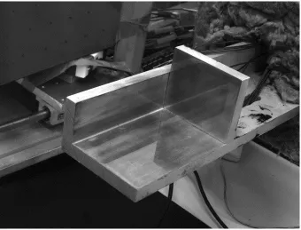
3.8 (a)The Aluminum Die. (b) 13 areas each with a thermocouple. . . 35
3.9 Schematic of the Aluminum Die. . . 35
3.11 Stereo-calibration. (a) Image from Vision Camera. (b) Image from
Thermal Camera. . . 37
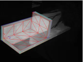
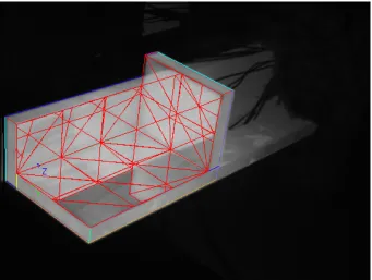
3.12 (a) 3D shape model representation of Aluminum Die. (b) 3D model using triangular subsurfaces defining the Aluminum Die. . . 38
3.13 Effect of ambient light on Aluminum Die, for the Vision and Thermal Camera. . . 41
3.14 Raw pixel values vs Temperature at numerous exposure times. . . 42
3.15 Normalized intensity Value vs Temperature. . . 43
3.16 Normalized intensity value vs temperature, with trend line. . . 44
3.17 Outline of the temperature measurement procedure. . . 45
3.18 Raw image from the Vision Camera. . . 46
3.19 Raw image from the Thermal Camera. . . 46
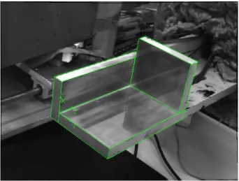
3.20 Image from the Vision Camera, showing the pose determined by 3D shape matching. . . 47
3.21 Image from the Thermal Camera, showing the pose determined by pose composition. . . 47
3.22 Image from Thermal Camera showing the partitioned regions, when RMax = 0. . . 49
3.23 Image from Vision Camera showing the partitioned regions, when RMax = 0. . . 49
3.24 Image from Thermal Camera showing the partitioned regions, when RMax = 1. . . 52
3.25 Image from Thermal Camera showing the partitioned regions, when RMax = 2. . . 52
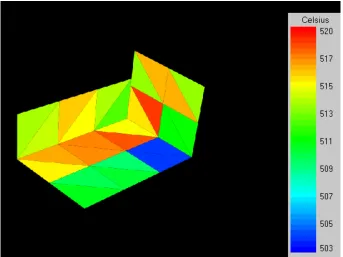
3.26 Color coded temperature image created from temperature measure-ment, using RMax = 2. . . 56
4.1 Experimental setup. From left to right: infrared, Thermal, and Vision Camera. . . 58
4.2 Experimental setup. (a) Die outside of the furnace. (b) Die inside of the furnace. . . 58
4.3 Data from all considered images, at RMax = 2, and Emissivity = 0.7. 64 4.4 Image taken by infrared camera with emissivity set to 0.20. . . 66
4.5 Image taken by infrared camera with emissivity set to 0.32. . . 66
4.6 Overview of the laboratory die casting process simulator. . . 67
4.7 Schematic of the Cooling Die Insert. . . 68
4.9 Images from the final cycle. (a) Vision Image. (b) Thermal Image. . . 71
4.10 Temperatures of Regions 1, 2, and 3, at each cycle. . . 72
4.11 Temperature difference between Regions 1 and 2 compared to Target Region 3, at each cycle. . . 72
4.12 Amount of coolant used in Region 1 and 2, for each cycle. . . 73
A.1 Effect of reflections on infrared imaging. Actual surface temperatures are essentially uniform. . . 79
A.2 Simplified 3D model of the Aluminum Die. . . 80
A.3 Partitioning with RMax set to 0. . . 81
A.4 Partitioning with RMax set to 1. . . 81
A.5 Partitioning with RMax set to 2. . . 81
A.6 2D diagram of three die subsurfaces imaged by camera. . . 87
A.7 Initial region of subsurface 0 projected in image. . . 87
A.8 Points reflected on subsurface 0. Reflections are present from 1’ and 2’ in some parts of the initial region ∼ 0. Current depth of reflection = 1. 88 A.9 Points reflected on subsurface 2. Reflections are present from 2”. Depth of reflection = 2. . . 88
List of Tables
3.1 Average effect of dark current on pixel value at different exposure times 39
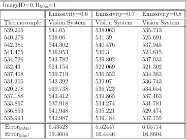
4.1 Temperature measurement results: ImageID=0 and RMax=0 . . . 61
4.2 Temperature measurement results: ImageID=0 and RMax=1 . . . 61
4.3 Temperature measurement results: ImageID=0 and RMax=2 . . . 62
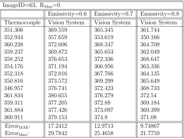
4.4 Temperature measurement results: ImageID=63 and RMax=0 . . . . 62
4.5 Temperature measurement results: ImageID=63 and RMax=1 . . . . 63
Chapter 1
Introduction
1.1
Contact and Non-Contact Temperature
Mea-surement
Methods used for temperature measurement in the industry can be separated into
two main categories: contact and non-contact methods.
Contact temperature measurement methods include thermocouples, thermistors,
resistance temperature detectors (RTDs), and liquid-in-glass thermometers, and rely
on a transfer of heat energy from the material to the sensor. While the technology
behind such temperature measurement methods is well known and used throughout
industry, they carry several drawbacks [5–7]:
• A sensor is required for each temperature measurement sample, making it diffi-cult to measure temperature over a wide area and with high resolution.
• The temperature of the sensor must reach thermal equilibrium with the mate-rial for accurate measurement, increasing the response time of the sensor when
temperature changes.
• The sensor must be installed to have contact with the material at the desired location, which can be impractical in restrictive spaces, or where the material must be free to move.
Non-contact temperature measurement methods overcome these issues, because
they do not require a transfer of heat energy though mass, and include single-color
infrared wavelengths, and are often referred to as infrared imagers/cameras. However,
there has been a growing interest in using standard cameras such as charge-coupled
device (CCD) cameras for pyrometry, mainly because of low cost, and their response to near-infrared wavelengths.
All pyrometers rely on the ability of the material to emit thermal radiation, and
to reflect and absorb incident radiation in a predictable manner. Issues that
non-contact methods must overcome include varying and uncertain emissive and reflective
properties of the material, as well as reflecting radiation generated from ambient
sources.
1.2
Die Casting Processes
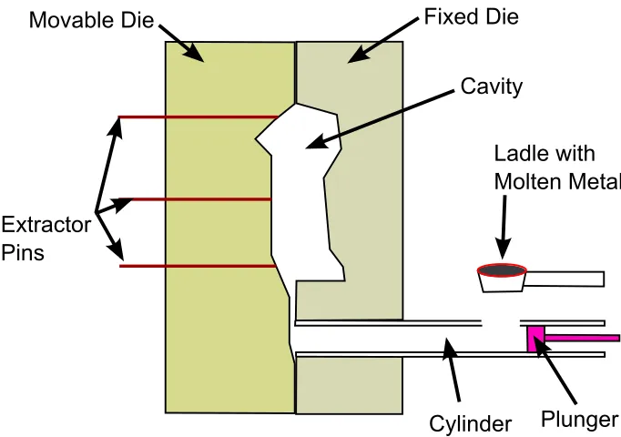
Die casting is a manufacturing process in which molten metal is forced into a cavity
inside of a reusable mould, called the die. In the cavity, the metal solidifies and takes the shape of the cavity. In order to remove the solidified metal, called the casting,
the die is constructed of two main sections: one stationary section called the fixed
die half, and one section that is moved by a hydraulic press, called the movable die
half [9–11]. Figure 1.1 shows the main components of a die casting machine.
Fixed Die
Cavity
Ladle with Molten Metal
Plunger Cylinder
Extractor Pins
Movable Die
Figure 1.1: Main components of a die casting machine.
One die casting production cycle can be broken down into four main sections:
and blown by compressed air, to reduce the temperature of the die from the
previous cycle and to lubricate the surface for the upcoming steps.
2. Cavity filling: The two die halves are clamped together with a hydraulic press. Molten metal is poured into the cylinder, and is injected into the cavity using a
plunger.
3. Solidification: While still under pressure from the hydraulic press, the molten
metal solidifies inside of the die. Water cooling is used to reduce the solidification
time.
4. Casting Ejection: The die two halves are separated and the casting is ejected
from the die. The casting is then removed by an operator or a robot.
The die serves two major roles: to determine the shape of the solidified casting,
and to rapidly draw heat during the solidification phase. Both of the die halves are
usually constructed of many individual die inserts. Each die insert can have one or
more internal water cooling lines. The purpose of the water cooling lines is to shorten
the cycle time in order to increase production yield, and to have control over the temperature of the die insert.
Having control of the temperature of the die inserts is most crucial during the
solidification process, which is done by adjusting the water flow rates for each of the
cooling lines. In industry, this is usually done manually by experienced operators,
typically using trial-and-error. The water flow rate configuration can have a large
impact on the thermal conditions that the casting experiences during solidification.
1.3
Motivation and Objectives
The thermal conditions that the casting experiences during solidification play a major
role in the quality of the casting. However, traditional methods for temperature
con-trol, such as trial-and-error, often lead to a very nonuniform temperature distribution
on the die surface, which may lead to a range of casting defects. Over-cooled regions
of the die can lead to defects such as poor fill, while under-cooled regions of the die
can lead to defects such as porosity and hot tearing [12]. Furthermore, issues such
as partial or full clogging of the water cooling lines can affect the performance of the
Die casting manufacturers are motivated to reduce cost and increase the
produc-tion yield, in the face of increasing competiproduc-tion. The objective of this research is
to develop a low-cost, vision-based, die casting temperature measuring and thermal management system. The system must be able to accurately monitor the temperature
of the die using standard cameras1, and adjust the water cooling of the die in order
to minimize the temperature variation on the die. The majority of the focus is placed
on developing an accurate temperature measurement system using standard cameras.
1.4
Literature Survey
1.4.1
Temperature Measurement using Standard Cameras
It has been known for a long time that standard cameras can be used for pyrometry, particularly due to the fact that their sensitivity to light extends slightly into the
infrared region. In fact, the main difference between the sensors in CCD cameras and
the sensors in dedicated pyrometers/infrared cameras involves the wavelengths of the
electromagnetic spectrum that the sensors can detect. The literature survey regarding
camera-based temperature measurement is categorized by pyrometry method.
Single-Color Pyrometry
[13–15] Single-color pyrometry uses one sensor element to absorb radiation in a range
of wavelengths. This range mostly depends on the material of the sensor. The sensor’s
response to the radiation is used to infer the temperature of the material, either using
a lookup table (LUT), or a mathematical relation. These pyrometry systems usually
allow the user to manually set an approximated emissivity value2. The closer the
set emissivity value is to the actual emissivity of the material, the more accurate the
temperature measurement will be.
CCD camera implementations of single-color temperature usually rely heavily on
the narrow range of infrared wavelengths that the CCD is sensitive to, and generally use infrared-pass optical filters to block visible light from affecting the image.
J. Chen et al. [13] develop a CCD camera LUT approach that achieves accuracy
similar to a commercial pyrometer. This is achieved in laboratory settings, where the
1A standard camera refers to a charge-coupled device (CCD) camera, in contrast to an infrared pyrometer/camera that is specifically designed for temperature measurement.
same material used for calibration is used to verify the system, which bypasses the
issue of emissivity.
E. Renier et al. [14] examine the temperature vs. camera response relationship, and the effects that different filters have on the relationship.
T. Sentenac et al. [15] present radiometric and geometric models for temperature
measurement using CCD cameras. The spectral sensitivity of the sensor is explored,
along with the sources of noise within the sensor, including the sensor-temperature
dependant dark current effect. Through modeling of the sensor, a relationship for
temperature measurement is determined and verified.
The single-color pyrometry method is the simplest approach, and is also the most
sensitive to emissivity approximation error. For many materials, emissivity in not
invariant. It can change as the temperature or surface condition of the material changes, and its value can differ at different wavelengths.
Two Color or Ratio Pyrometry
[7, 16–18] Ratio pyrometry generally uses two sensors, each to absorb radiation at
two separate and narrow ranges of wavelengths. The two ranges of wavelengths are
referred to as the two colors that the specific pyrometer uses. Ratio pyrometry does
not rely on knowledge regarding the emissivity of the object, but does rely that the emissivity is of identical value at the two colors. If this assumption is true, then the
ratio of the responses from the two sensors is unique for each temperature, and is
unaffected by variation in emissivity.
CCD camera implementations use two narrow ranges of wavelengths, or colors,
within the range of wavelengths to which a CCD camera is sensitive. A relationship
is established between the ratio of the camera’s response at the two colors vs. the
temperature of the material. One approach uses a single monochrome camera3, and
two optical filters on a system that quickly moves the filters in front of the camera,
in order to take two images using two different colors [16]. Another approach uses
two cameras with fixed optics and a beam splitter, so the two images can be taken simultaneous [17].
The most recent research regarding temperature measurement using standard
cam-eras is focused on ratio pyrometry using a single commercially available color CCD
camera. Color cameras internally have alternating red, green, filters on the pixels. The
ratio between the different colored pixels can be used to determine the temperature
of a material [7, 18].
Ratio pyrometers generally cannot be used on materials whose emissivity can have different values at the two colors. Also, since enough radiation must be absorbed at
both of the colors to determine a meaningful ratio, the ratio pyrometer can’t be
implemented to measure temperatures as low as the single color pyrometer can.
Multi-Color Pyrometry
[17, 19, 20] Multi-color pyrometry uses as low as three, but often many more narrow
wavelength bands, to determine the spectral emission of the object across a wide range of wavelengths. It does not require an estimate regarding the emissivity of the object,
and it can reliably measure temperature of objects whose emissivity varies at different
wavelengths. This method is relatively new regarding not only CCD implementation,
but also implementation using standard pyrometers.
Notes
While many CCD camera temperature measurement systems have been developed, only a small number of issues that affect accuracy are addressed: mainly those that
arise even under laboratory settings, such as dark current noise. No work seems to
exist regarding real-world issues that affect CCD-based temperature measurement,
particularly issues that arise in an industrial die casting setting. Therefore, this work
focuses on identifying and overcoming issues that can cause unreliable temperature
measurements in such industrial settings.
Most of the current work listed focuses on industrial applications involving very
high temperatures, usually greatly over 800 ◦C. These temperatures are not relevant
for most casting processes: the average die temperature once the casting is removed is
usually below 400 ◦C [21]. At such low temperatures, the emitted thermal radiation is strong enough to have a measurable response by the CCD sensor only over a very
small range of wavelengths that the CCD sensor can detect. Segmenting this small
range of wavelengths into colors for two color or multi-color pyrometry is difficult.
More importantly, since each color must have a measurable response, using two or
multi-color pyrometry would increase the minimum temperature that the system can
measure. To increase the range of temperatures that the system can measure, this
1.4.2
Thermal Management Systems
In the past, various approaches have been taken in developing a thermal management
system for die casting processes, using different methods to measure the temperature
of the die or casting. The literature survey regarding casting thermal management
is categorized by temperature measurement method. Some major approaches are
categorized below.
Thermocouple Approaches
[22] A hole is drilled into the die insert and a thermocouple is placed at each region
where temperature measurement is required. To obtain useful information, the hole
is drilled so the thermocouple is close enough to the surface of the die that is in
contact with the solidifying casting. With the temperature data of the die inserts,
the cooling system can be modified using a number of methods, including On-Off
Solenoid Valve Control, Proportional-Integral-Differential (PID) Control, or Fuzzy
Control. The benefit of using thermocouples is that continuous temperature data is
available so the cooling can be controlled throughout the solidification process. The drawbacks of thermocouples include:
• Drilling cost: drilling numerous holes that are narrow and deep through tool steel is very expensive.
• Die life: the introduction of holes in the die reduces the life of the die, increasing the overall cost of operation.
• Measurement density: Each measurement requires a separate thermocouple. Therefore the temperature of the die cannot be densely monitored.
• Measurement accuracy: The measured temperature can vary greatly even with a small change in position of the thermocouple in a die insert. This is because
of the thermal dynamics of the die: the effect of the water cooling lines, the
geometry of the die inserts, and the heat from the solidifying casting, can cause large temperature variation over very small spaces. Also, the thermocouple is
known for poor tracking when temperature is quickly changing.
Infrared Camera Approaches
[12,23] An infrared camera is used to monitor the temperature. One approach requires
of the casting as it solidifies, in order to adjust the cooling of the die. Since transparent
dies are not used in the industry, this approach is not practical. Another approach uses
an infrared camera to directly measure the die surface temperature when the casting is removed. The benefits of using infrared cameras is that no physical contact is required,
while achieving a denser temperature measurement than with thermocouples. The
drawbacks of infrared cameras include:
• Measurement accuracy: most infrared cameras use sensors that respond to radi-ation in the 8 to 14 µm wavelength range. At the relatively high temperatures
that are used in casting processes, large errors in measurement can be caused
by emissivity variation and reflections.
• Camera cost: Each infrared camera can cost between $10,000 to $20,000.
• Resolution: Most infrared cameras have a resolution smaller than 400 by 300 pixels.
Up to now, CCD cameras haven’t been applied for high pressure die casting
tem-perature measurement and temtem-perature control.
1.5
Thesis Outline
Chapter 2 provides some preliminary theories regarding thermal radiation, CCD
cam-eras, and geometry, which are required for the other chapters. Chapter 3 presents the
developed CCD camera temperature measurement system. Chapter 4 presents the
experimental validation of the developed temperature measurement system, as well
as a case study for closed-loop temperature control of die casting processes using CCD
Chapter 2
Background
2.1
Electromagnetic Radiation
It is well known that all materials above absolute zero temperature emit
electromag-netic radiation across a range of wavelengths. This radiation is strongly dependant
on the temperature and physical properties of the material, and is called thermal
ra-diation. As shown in Figure 2.1, the visible spectrum of electromagnetic radiation is roughly 0.4µm to 0.7µm, and the infrared spectrum is roughly 0.7µm to 1000µm [1].
2.1.1
Blackbody Radiation
A blackbody is an idealized material that emits the maximum amount of thermal
radiation for any given temperature, and absorbs all incident radiation. Thespectral
emission of a blackbody is described by Planck’s Law [24], which is given in Equation
2.1.
LBBλ = 2×10
18c
λ4
1
e106hc/µkT
−1 photon s −1
m−1sr−1λm−1 (2.1)
where:
• Lλ is the spectral radiance of a blackbody at a specific wavelength λ.
• BB denotes the radiance is from a blackbody.
• T is absolute temperature of the blackbody in Kelvin.
• c is the speed of light.
• h is Plancks constant.
• k is Boltzmanns constant.
Figure 2.2 shows the spectral emission of a blackbody due to Planck’s Law, at temperatures relevant to the casting process.
2.1.2
Emissivity
Actual materials, as opposed to the theoretical blackbody, emit a fraction of the
radiation that a blackbody emits. This is described by theemissivity of the material,
denoted by , which can have a value between 0 and 1. A blackbody is said to have
= 1. If emissivity of a body is independent of wavelength, the body is referred to
as agraybody, and if emissivity of a body varies with wavelength, the body is referred
to as anon-graybody.
The spectral emission from actual materials in relation to a blackbody can be
expressed as:
Lλ =LBBλ (2.2)
Figure 2.3 demonstrates the thermal emission from a blackbody, a graybody, and
0 2 4 6 8 10 12 1016 1017 1018 1019 1020 1021 1022
1023 Spectral Emission of a Blackbody at Various Temperatures
Wavelength (µm)
Photon Emissi
on per second pe
r sq uare meter 600 C 500 C 400 C 300 C
Figure 2.2: Blackbody photon emission at various temperatures, according to Planck’s Law.
0 5 10 15 20 25
0 2 4 6 8 10 12 14 16 18x 10
20 Spectral Emission of Blackbody, Graybody, and Non−Graybody
Wavelength (µm)
Photon Emissi
on per second pe
r
sq
uare meter
Blackbody (ε=1) Graybody (ε=0.8)
Non−Graybody (Varying ε)
Emissivity and Emittance
Emissivity and emittance are used to describe the same phenomenon. Emissivity
describes the radiative properties of a material, such as of pure aluminum or iron,
while emittance describes the radiative properties of a specific object. Emissivity is
one factor that determines the emittance of an object, along with other factors such
as the surface conditions or temperature of the object. If the object has a clean and
optically smooth surface, and is thick enough to be opaque, then the emittance of the
object approaches the emissivity value [25].
While this technical distinction does exist, the two similar terms are often used
interchangeably without confusion, including within this work.
Emissivity of Relevant Materials
Many sources exist providing emissivity values of common materials intended for use
with commercially available infrared imagers [26, 27]. The emissivity values are given
only as guidelines, by a single number or a narrow range of values, which are valid for wavelengths that infrared imagers use. However, CCD cameras are not sensitive to
the same wavelengths as a commercial infrared camera, so the given emissivity values
cannot be used by CCD camera systems.
Touloukian and DeWitt [25] examine in greater detail the properties of
emissiv-ity (emittance), absorptivemissiv-ity, reflectivemissiv-ity, and transmissivemissiv-ity of numerous materials
over a wide range of wavelengths and surface conditions. From their data regarding
aluminum, iron, and stainless steel, the following conclusions can be made:
• Spectral Emittance: The three materials have similar patterns regarding emit-tance throughout the observed spectrum. Notably, emitemit-tance is significantly
higher at wavelengths around 1 µm, and is rather low at wavelengths near 10
µm. This is important because CCD cameras are sensitive to wavelengths near
1 µm, while typical industrial infrared cameras are sensitive to wavelengths in
the 8 µm to 14 µm range [2, 28].
• Surface Conditions: For all three materials, a highly polished surface protected from oxidization has significantly lower emittance than an oxidized or roughly
polished surface. This is also explored by Yang [12], regarding the effect that
roughness and oxidization of a surface has on its emittance.
one material can be used to measure the temperature of any similar material.
2.1.3
Absorbtion and Reflection of Incident Radiation
Electromagnetic radiation incident upon a surface of a material is either absorbed,
reflected, or transmitted by the material [29], as shown in Figure 2.4. The ratio of the
incident light that is absorbed, reflected, or transmitted by the material is represented by the absorptivityα, reflectivityρ, and transmissivityτ. Intuitively, the relationship
betweenα,ρ, and τ is:
Figure 2.4: Reflection, absorption, and transmission of incident radiation.
α+ρ+τ = 1 (2.3)
As previously stated, a blackbody is an idealized material that absorbs all incident
radiation, so it can be said that for a blackbody α= 1, ρ= 0, and τ = 0.
For the purposes of this study, relevant objects are opaque to thermal radiation,
meaning that τ = 0. Therefore, Equation 2.3 can be simplified to:
α+ρ= 1 (2.4)
Focusing on a small interval of wavelengths centered around any specific
wave-lengthλ, a relationship can be made between emissivity, absorptivity, and reflectivity
of a material [30]:
ρλ = 1−λ (2.6)
This relationship allows all terms to be known once the emissivity is determined.
Note that the specific values of αλ, λ, and ρλ are often different at different lengths, since the same material can have different emissivity values at different
wave-lengths. Also, a similar distinction is made between absorptivity and absorbance, and
reflectivity and reflectance, as is made with emissivity and emittance. Once again,
these terms are used interchangeably without confusion.
2.1.4
Effect of Reflections on Temperature Measurement
Depending on the surface properties of the material, incident radiation that reflects
from a material can be described to be either specular, diffuse, or a combination of
the two. Specular reflections are mirror-like reflections where the angle of incidence
equals the angle of reflectance, while diffuse reflections scatter the incident radiation
in many directions, as demonstrated by Figure 2.5.
α β
Figure 2.5: Specular and diffuse reflections.
Disregarding polarity, reflected radiation becomes indistinguishable from the
ra-diation that is emitted by the surface. If a thermal imager is used to determine the
temperature of a surface based on the apparent thermal radiation from the surface,
the reflecting radiation can make the surface appear significantly hotter than it really
is.
Figure 2.6 demonstrates how thermal reflections can combine with the thermal
SUR
F
AC
E
1
SUR
F
AC
E
3
SURFACE 2
Figure 2.6: Combination of reflected and emitted radiation that reaches the imager.
Assuming that Surfaces 1, 2 and 3 in Figure 2.6 have the same emissive
prop-erties, and focusing on a small interval of wavelengths centered around any specific
wavelengthλ, the intensity of radiation reaching the camera can be expressed as:
Lλtotal =λLλSurface1+ρλλLλSurface2+ρλρλλLλSurface3 (2.7)
where:
• Lλtotal is the total radiation for wavelengths centered around λ that reaches the camera from a region of Surface 1.
• λ is the emissivity of Surfaces 1, 2, and 3 valid of wavelengths centered around λ.
• ρλ is the reflectivity of Surfaces 1, 2, and 3 valid of wavelengths centered around λ.
• LλSurfacei, where i={1,2,3} is the radiation emitted by a blackbody at temper-ature of Surface 1, 2, or 3.
Combining Equations 2.6 and 2.7:
It can be said that for the differential area element of Surface 1 that is being
con-sidered, thedepth of reflection = 2, because it contains the reflections of a differential
area of Surface 2, which contains the the reflections of a differential area of Surface 3. Since radiation is partially absorbed at each reflection, the deeper a reflection is, the
less impact it generally has.
2.2
CCD Camera
This section contains a brief overview of the CCD camera sensor, focusing on aspects
that are relevant for the system developed in Chapter 3.
Most cameras used for machine vision purposes use a charge-coupled device (CCD) as the camera sensor. The sensor has an array of light sensitive cells called pixels.
A photon of light that reaches a pixel on the sensor has a probability of exciting an
electron. A pixel is exposed to light for a set period of time called theexposure time,
during which the generated electrons are stored. These generated electrons are then
used to determine the numerical value for each pixel, which is usually represented by
an 8 bit binary number. The 8 bit representation allows a resolution of 28 or 256
values, so the pixel value is an integer from 0 to 255. A pixel value of 0 represents
black, while 255 represents white, with values in between denoting shades of gray.
Note that 10 bit or higher cameras exist.
The sensor has a highly linear relationship between the number of excited electrons and pixel value, making it very suitable for radiometry. It should be noted that many
cameras have the option of using a non-linear light intensity to pixel value relationship,
which is controlled by the gamma correction. Setting gamma to 1 allows the camera
to perform in the desired linear manner.
A pixel is said to be saturated if the number of excited electrons is equal to or
higher than the number required to have a pixel value equal to 255. A saturated
pixel cannot be used for radiometry, because it is uncertain how many electrons were
excited.
2.2.1
Monochrome Spectral Response
The ability for the CCD sensor to generate excited electrons from incoming light is characterized by its spectral response. For each wavelength, a CCD camera has a
different probability of having an electron excited by a photon. This probability is
is given as the percent of photons that excite an electron. While the structure of the
CCD plays a role in determining the QE, the most influential aspect of the sensor is
that it is made from silicon. As such, most CCD cameras have comparable spectral responses. They are generally sensitive to wavelengths roughly from 0.4 µm to 1.05
µm, and therefore sensitive to infrared radiation roughly from 0.7 µm to 1.05 µm,
which is a region in the near-infrared spectrum. Figure 2.7 shows the spectral response
of a typical CCD camera [2].
0.4
0.5
0.6
0.7
0.8
0.9
1.0
Wavelength (µm)
60
50
40
30
20
10
0
Q
uan
tu
m
Ef
ficie
ncy
(%
)
Sensor Response
Figure 2.7: Typical sensitivity of silicon based CCD camera [2].
Because the CCD camera is sensitive to a wide range of wavelengths that span the
visible and near-infrared, optical filters can be used to limit which wavelengths reach
the sensor. In this study, two cameras are used, and each using different filters. This
is given in detail in Chapter 3.
2.2.2
Inherent Noise in CCD Sensor
Three types of noise are considered for the CCD sensor: dark current noise, salt and
pepper noise, and Gaussian noise.
As mentioned, photons that reach the sensor excite electrons, which are then used
to measure the light that reached the sensor. However, some electrons are not excited
by photons, but instead are thermally excited within the sensor. The phenomenon is
sensor and the exposure time. The thermally generated electrons are indistinguishable
from the photon generated electrons, and therefore can cause errors in radiometry [15].
A simple method known as dark-frame subtraction is used to reduce the effect of dark currents. This method requires taking one or more images with no light reaching
the sensor, and averaging the pixel values in order to determine the average effect that
the dark current has on the pixel values. This determined average pixel value is then
subtracted from the pixel values of subsequent images [31].
Salt and pepper noise also affects CCD cameras, and is characterized by a low
probability of any individual pixel to have a very large or small value, regardless of
the incident light. The occasional random scattering of black and white pixels gives
rise to the name. The effect of salt and pepper noise is reduced using median image
filtering, before any Gaussian or averaging filtering is performed [32].
The final sources of noise considered are generalized as Gaussian noise, which is
an additive/subtractive noise with a Gaussian distribution. The effect of such noise
is reduced using Gaussian filters, or by averaging pixel values [32].
2.3
Geometry
2.3.1
Euclidean Geometry
Euclidean transformations represent translations and rotations in 3D space. These
linear transformations have 6 parameters: three coordinates and three angles1 for translation and rotation, respectively as depicted in Figure 2.8.
Let p and p0 denote the same point in space, where p= [x, y, z]T is defined with
respect to an arbitrary reference frame. p0 = [x0, y0, z0]T is defined in a different
reference frame. The relationship between p and p0 is:
x0 y0 z0 =
r11 r12 r13
r21 r22 r23
r31 r32 r33 x y z + tx ty tz (2.9)
p0 =Rp+T
whereR is a 3×3 rotation matrix, and T is a three-element translation vector. The above relation can be written in compact form using homogeneous coordinates
1Note that the three angles of rotation can be computed from the 3
x y z φ θ ψ
Figure 2.8: Coordinate Frame with Fixed Axis Rotation Convention
x0 y0 z0 1 =
r11 r12 r13 tx
r21 r22 r23 ty
r31 r32 r33 tz
0 0 0 1
x y z 1 (2.10)
p0 =Dp
whereD is a 4×4 matrix representing a mapping from R3 to R3.
2.3.2
Pose
Geometrically, a camera is represented by the position and orientation of the center
of projection, termed the pose of the camera. The pose of an object represents the
position and orientation relative to a reference frame. Equation 2.10 can be used to
represent the pose of an object in the reference frame of a camera, in this case p
is a point in the object’s reference frame, and p0 is the same point expressed in the camera’s reference frame, then D is the mapping from the reference frame of p to that of the camera.
The operation in Equation 2.10 can be inverted using the inverse of a pose p =
D−1p0, we can representp in the original reference frame, this is denoted by
p=D−1p0 =R−1p0−R−1T (2.11)
A succession of pose transformations that share a reference frame between each
frame of an object of interestP, the pose of the object in the reference frame of camera
A, and the pose of camera A in the reference frame of camera B, then the pose of p
with respect to camera B is given by:
p0 =DABDP Ap =RAB(RP Ap+TP A) +TAB (2.12)
wherep0 representspin the reference frame given by the pose composition operation. It transforms the reference frame ofP toA and from A toB.
2.3.3
Perspective Projection
The pose of a camera is represented by the pose of the center of projection O. The
image plane is parallel to the axisOx andOy. The axisOz is referred to as the optical
axis. x y z x y z O p (Ou, Ov) Image coordinate
system (pixels) u v p’ p’’ P Camera coordinate system Object coordinate system
Figure 2.9: Perspective Projection Model
Given the relationship between an object P and the camera center O, we can
express a pointpasp0 in the reference frame of the camera. Then, using the Pinhole model, [33], we can project p0 onto the image plane as follows:
p00 =hsf u
p0x
p0
z +ou, f sv
p0
y
p0
z +ov iT
(2.13)
wheref is the focal length of the camera, (ou, ov) are the coordinates of the center of
projection in the image plane, and (su, sv) are the dimensions, in units of length, of the sensor’s pixels. The projection model is shown in Figure 2.9.
x00 y00 1 = f
su 0 ou 0 sf
v ov
0 0 1
1 0 0 0 0 1 0 0
0 0 1 0
r11 r12 r13 tx
r21 r22 r23 ty
r31 r32 r33 tz
0 0 0 1
x y z 1 (2.14)
p00 =AIDp
where I maps from the 3D camera coordinate system to the 2D coordinate system,
Chapter 3
Development of CCD-Based
Temperature Measurement for Die
Casting
3.1
Overview
To reduce the formation of defects in a casting process, it is desirable to minimize
temperature variation on the casting during the solidification phase. The die has
physical contact with the casting during the solidification phase, and therefore the
temperature of the die correlates to the temperature of the casting. Therefore, the
problem is transferred to control the temperature variation on the die, which requires
accurate temperature measurement of the die.
In order to implement a CCD-based temperature measurement system that is not intrusive or disruptive to the current casting process, the die can only be imaged
during the the extraction phase of the casting cycle. Therefore, the only temperature
information available shows the temperature distribution of the die immediately after
the solidification process completes. Figure 3.1 shows how the vision system would
be physically incorporated into the current die casting system without disrupting the
casting process. Note that at least two separate camera systems are ultimately needed
since there are two separate die halves, and that the camera systems can be placed
on either side of the casting machine, not necessarily on top as shown in the figure.
The basic concept behind die temperature measurement using CCD cameras is as follows. The die surface emits thermal radiation over a wide range of wavelengths,
depending on the temperature of the die. At a sufficiently high temperature, the die
Ca mera System
Camer a
System
Fixed Die
Ladle with Molten Metal
Plunger Cylinder
Extractor Pins
Movable Die
Figure 3.1: Incorporating a vision-based temperature measurement system into the casting process.
and the camera yields a response that can be interpreted as a thermal image. This temperature is called the minimum measurable temperature. The pixel values of the
camera continue to increase as the temperature of the die surface increases, until the
pixels become saturated. Once the pixels become saturated, a smaller exposure time
is required to create useful images at the higher temperatures. It is assumed that the
largest practical exposure time had been used up to that point.
The minimum measurable temperature that the CCD camera can measure depends
on the amount of noise in the environment and in the camera. For example, in this
work the minimum measurable temperature is near 310 ◦C. If the die surface is at
or above the minimum measurable temperature, the camera’s response can be used to determine the temperature of the die, using a pre-determined
camera-response-to-temperature relationship.
The main weakness of a CCD camera-based temperature measurement system is
3.2
Factors Affecting Accurate Temperature
Mea-surement in an Industrial Setting
To achieve reliable temperature measurement of casting dies in an industrial setting,
it is necessary to identify issues that can affect the temperature measurement. Most
of these issues can cause inaccurate measurements, regardless of which pyrometry
method is being utilized, or whether CCD cameras or infrared pyrometers/cameras
are being employed. Each identified factor is discussed individually, along with the
general method developed to overcome the effect of the factor.
3.2.1
Emissivity
Most dies are made from tool steel, and their surface is kept rust-free by the use
of lubricants and frequent maintenance. Also, the high pressure injection of molten metal during the process can remove collected buildup on the die surface [34]. As
such, the emissivity of the die is relatively low, which in general makes temperature
measurement more difficult, by decreasing the emitted radiation and increasing the
reflected radiation.
Also, while all dies are maintained and are lubricated during the casting process,
the surface conditions of the dies slowly changes between maintenance, and therefore
so does the emissivity (emittance) of the dies.
Compared to standard infrared cameras, a CCD camera pyrometer is ideal for this
situation, because the emissivity of relevant materials is maximal at the wavelengths in which the CCD sensor operates, as described in Section 2.1.3. Also, at the
temper-atures relevant to the casting processes, the variance in emissivity causes less error
for a CCD camera pyrometer compared to a standard infrared camera. Figure 3.2
demonstrates that a small change in temperature results in a large change of
pho-ton emission at wavelengths that a CCD camera detects, while the same change in
temperature results in a much smaller change in photon emission at wavelengths that
an infrared camera detects. Thus for a CCD camera pyrometer, a change in photon
emission due to a change in emissivity results in a very small change in the measured
0 2 4 6 8 10 12 1016
1017 1018 1019 1020 1021 1022
1023 Spectral Emission of a Blackbody at Various Temperatures
Wavelength (µm)
Photon Emissi
on per second pe
r
sq
uare meter
600 C 500 C 400 C 300 C
Figure 3.2: Blackbody photon emission at relevant temperatures. Vertical lines at 0.7 µm to 1.05 µm show the near-infrared sensitivity range of CCD cameras. The sensitivity range of infrared cameras in generally at 8 µm to 14 µm.
3.2.2
Pose of the Die
To accurately determine the temperature distribution of the die surface, it is necessary
to determine the pose of the die relative to the camera. With the pose of the die
relative to a camera, it is possible to determine where any 3D point of the die’s
surface is projected in the image plane, as explained in Section 2.3.
The methods typically used to estimate the pose of objects1, such as 3D shape
matching, cannot be reliably applied to the images from a CCD camera pyrometer.
The pyrometer must use optical filters to block visible light from affecting the image
so the pixel values are mainly influenced by the thermal radiation emitted from the
die, meaning that the images are unreliable for pose estimation.
To solve this issue, a second CCD camera is used for reliable pose estimation. This
camera uses only visible light for imaging and using filters is unaffected by thermal
radiation. This camera is referred to as the Vision Camera, and its images are referred
to as Vision Images. In contrast, the camera used for temperature measurement is referred to as the Thermal Camera, and its images are referred to as Thermal Images,
since it uses thermal radiation for imaging. Once the pose of the die relative to Vision
Camera is determined, the pose of the die relative to the Thermal Camera can be
determined using the pose composition operation, as explained in Section 2.3.2.
3.2.3
Temperature Range and Pixel Normalization
As mentioned, the average temperature of the die is usually below 400 ◦C after the casting is extracted [21]. However, the actual temperature distribution of the die can
span over a wide range of temperatures, especially if considering the full range of
casting processes in the industry. Due to the wide range of emitted thermal radiation
intensities at these temperatures, as demonstrated in Figure 3.2, the temperature
measurement system must allow the user to choose an appropriate exposure time, so
the pixels are not saturated or too dim.
To enable the temperature measurement system to function over a wide range
of exposure times, a normalization procedure is developed to transform pixel values
to a relative intensity value that is independent of exposure time: P → I. This normalization procedure also removes the dark current effect noise inherent in CCD
sensors. The normalized intensity value is referred to asIV ision when performed on a
region in the Vision Image, andIT hermal when performed on a region in the Thermal
Image.
3.2.4
Determining Temperature
For temperature measurement, it is required to develop a method of calculating the
temperatures from the response of the Thermal Camera. Based on the discussion
regarding emissivity in Section 3.2.1, this method must allow the user to estimate
the emissivity of the die surfaces prior to determining the temperatures of the die
surfaces.
A relationship is empirically developed between the response of the camera in the
form of the normalized intensity value IV ision, and the temperature of a blackbody
that caused the response of the camera. Before the relationship is used to determine
the temperature of a surface from its normalized intensity value, the intensity value
is scaled by the emissivity. For this relationship, the normalized intensity value must
be a result only from the thermal radiation emitted by the surface whose temperature
3.2.5
Reflecting Radiation
As described in Section 2.1, opaque surfaces with an emissivity of less than one, reflect
a portion of incident radiation. The lower the emissivity of the surface, the more of
the incident radiation is reflected.
Two sources of infrared radiation exist within an industrial setting that can reflect
off of die surfaces: ambient lighting, and thermal radiation emitted from other hot
surfaces.
Reflection of Ambient Light
In industrial settings, the workplace is well illuminated by visible light. Most sources
of visible light such as incandescent bulbs, florescent bulbs, and sunlight, also emit
some infrared light. This infrared light can reflect on the surfaces of a die and
illumi-nate the die, increasing the apparent thermal radiation that is emitted from the die
surfaces.
Radiation is assumed to behave similarly across the visible and near-infrared
spec-trum to which the CCD camera is sensitive. With this assumption, the illumination that ambient light has on an object in the Vision Image should correlate to the
illu-mination that ambient light has on the same object in the Thermal Image.
A relationship is established regarding the illuminating effect that ambient light
has on a material when imaged by the two cameras. This relationship is represented
as a coefficient, CAmbient, that relates the effect of ambient light in the two cameras.
To eliminate the effect of ambient light on an area of the die projected in the Thermal
Image, the projection of the die area is found in the Vision Image. The pixel values
corresponding to the die area are averaged and normalized into a normalized intensity
value IV ision, and multiplied by CAmbient. The product of this is subtracted from the normalized intensity IT hermal determined for the die area in the Thermal Image. The
result of this is a modified intensity value, IM odT hermal, that has had the effect of
ambient light approximated and removed.
Reflection of Thermal Radiation
The radiation that reaches the camera from a region of the die contains not only
the thermal radiation emitted by that region, but can also contain thermal radiation emitted from other surfaces that are reflecting on the region. This effect is further
increased by the general concave shape of the die, where radiation can reflect numerous
Pyrometers using CCD cameras can only be affected by the reflections of thermal
radiation emitted from objects that are above the minimum measurable temperature.
It can be assumed that only the die surfaces are at or above this minimum temper-ature. However, most commercially available infrared cameras are affected by the
reflections from objects that are even at room temperature, because these objects
emit radiation that is detectable by the infrared cameras.
A method is developed to eliminate the effect of reflecting thermal radiation in
a CCD-based temperature measurement system. The method requires a 3D model
of the die: the die is divided into many small 3D triangular subsurfaces. Each
sub-surface is assumed to have a uniform temperature over the entire subsub-surface, and
the final output of the temperature measurement system is the temperatures of these subsurfaces.
With the predefined subsurfaces that define the shape of the die, and the relative
pose of the die determined using methods such as 3D shape matching, the image
from the Thermal Camera is partitioned into 2D regions. This partitioning is now
explained for one subsurface; this procedure is done for all subsurfaces.
The unoccluded projection of the subsurface is found as an initial 2D region in
the Thermal Image. Then, assuming perfectly specular reflections, this initial region
is partitioned into smaller regions, if the initial region contains reflections from other
subsurfaces. These reflections are solely determined by the pose and shape of the die, as defined by the 3D model of the die.
If a region of the initial region contains no reflections from other subsurfaces,
then the pixels in this region are influenced only by the thermal radiation from the
subsurface. For this region, the pixel values are normalized into IT hermal, and the
effect of ambient reflections is eliminated by findingIM odT hermal. Because no reflecting
thermal radiation is present, the determined IM odT hermal is the intensity value that
is caused only by the thermal radiation emitted from the subsurface, referred to as
ISubsurf ace. This ISubsurf ace is later used to determine the temperature of the 3D
subsurface.
However, it can happen that the entire initial region contains reflections of thermal radiation emitted from other subsurfaces. In that case, no pixel values or normalized
intensity values can be directly used to determine the temperature of the subsurface,
since they are influenced by the thermal radiation emitted from the subsurface that
is being considered, as well as the thermal radiation emitted from another subsurface
To determine the intensity value that is caused only by the thermal radiation
emit-ted from the subsurface,ISubsurf ace, the initial region determined by the subsurface is
partitioned into regions, so only one combination of emitted and reflected radiation from the subsurfaces influence the pixels in each region. For each partitioned region,
IM odT hermal is determined. The influence of the radiation emitted from the subsurfaces
on eachIM odT hermal can be described by an equation in the form:
IM odT hermal =ISubsurf ace iBB
IM odT hermal =ISubsurf ace iBB +(1−)ISubsurf ace jBB
IM odT hermal =ISubsurf ace iBB +(1−)I BB
Subsurf ace j +(1−)(1−)I BB
Subsurf ace k +. . .
where:
• IM odT hermal is the modified normalized intensity value determined from the pixel
values of the partitioned region.
• is the emissivity of the die subsurfaces, which is assumed to be equal for all surfaces.
• i, j, and k denote arbitrary subsurfaces. Thermal radiation from subsurface i
directly reaches the camera. Radiation from subsurface j reflects on the region
before it reaches the camera, while radiation from subsurfacekreflects on a part
of subsurface j, then reflects on the region before it reaches the camera.
• ISubsurf ace i/j/kBB is the normalized intensity that thermal emission from a black-body would induce in the Thermal Camera if at the same temperature as an
arbitrary subsurface i,j, or k.
Therefore, each partitioned region either directly determines the normalized
in-tensity of the subsurface, ISubsurf ace, and can be used to determine the temperature
of the subsurface; or more likely, it creates a single linear equation influenced by
nu-merous regions. The linear equations combine to create an over-determined system of linear equations, which is solved to determine the normalized intensity of all of the
subsurfaces. A weighted least-squares method is used: regions that are composed of
Before partitioning the image, a maximum depth of reflection to consider is set,
denoted with RMax. Considering deeper reflections will in general increase accuracy,
but decrease speed.
The developed temperature measurement system is now explained in detail.
3.3
Hardware
3.3.1
Camera System
Two identical CCD cameras are used as the key hardware for this study: the Prosilica
EC1350 imager, with a maximum resolution 1360 x 1024 pixels. The cameras are used
at a reduced resolution of 680x512. Figure 3.3 shows the two cameras in their final
position.
Figure 3.3: The two identical CCD cameras in their final setup. The Vision Camera is on the right of the image, while the Thermal Camera is on the right. They differ only in their purpose and optical filters.
Thermal Camera
One camera generates images using only the radiation in the small region of the
in-frared spectrum to which the CCD camera is sensitive. This camera is referred to
as the Thermal Camera, because its images mainly depend on the thermally
gener-ated radiation from the die where temperature is measured. An image taken by the
To limit the effect that ambient lighting has on its images, the Thermal Camera
uses an optical infrared-pass filter to block wavelengths that are in the visible
spec-trum: specifically, an X-Nite830 filter. The spectral properties of this filter is given in Figure 3.4 [3].
Figure 3.4: Spectral transmittances for the optical filters used on the Thermal Camera [3].
The purpose of the Thermal Camera is to determine the light intensity that is
thermally emitted from the die, and thereby the temperature of the die. The Thermal
Camera is the camera on the left in Figure 3.3.
Vision Camera
Another camera generates images using only the wavelengths in the visible spectrum.
This camera is referred to as theVision Camera, because its images represent objects
as how they appear to human eye, and its images are unaffected by the thermal
Image.
To prevent thermal radiation from affecting the Vision Camera, optical filters
are used to block wavelengths that are thermally generated in significant amounts by the die. Choosing which optical filter to use requires establishing a maximum
measurable temperature. The higher the maximum measurable temperature, the more
of the camera’s spectrum that the filter must block. Intuitively, the filter must block
the infrared region to which the CCD is sensitive. However, setting the maximum
measurable temperature sufficiently high requires blocking some of the wavelengths in
the visible spectrum. The maximum measurable temperature is chosen to be 600◦C,
since this is only about 50◦C below the melting point of aluminum and magnesium,
which are the most common materials used in die casting.
To substantially block the thermally generated wavelengths, two slightly different infrared-blocking filters are used: the SP625 and SP785 from Midwest Optical
Sys-tems. The spectral properties of these filters are given in Figures 3.5 and 3.6 [4]. Note
that some of the visible spectrum is blocked by the combination of the two filters.
The Vision Camera serves two purposes: to determine the pose of the die with
respect to the Vision Camera’s coordinate system, and to determine the effect of
ambient light on the Thermal Camera. The Vision Camera is the camera on the right
in Figure 3.3.
3.3.2
Casting Dies
Two dies are used to develop and validate the temperature measurement system:
Cylindrical Die Insert
The Cylindrical Die insert is used to develop the camera response vs temperature
relationship. It includes a hole for a thermocouple to be placed just behind the main
surface of the die. By measuring the temperature of the die with the thermocouple
and simultaneously imaging the die surface with a camera, it is possible to develop
a relationship between camera response and temperature. The Cylindrical Die insert
is made of H13 tool steel. The die is highly oxidized to maximize it’s emissivity, so a
0 10 20 30 40 50 60 70 80 90 100
350 450 550 650 750 850 950 1050
Tr an sm is si o n (% ) Wavelength (nm)
Spectral Transmission of SP625 Filter
Figure 3.5: Spectral transmittance of SP625 filter [4].
0 10 20 30 40 50 60 70 80 90 100
350 450 550 650 750 850 950 1050
Tr an sm is si o n (% ) Wavelength (nm)
Spectral Transmission of SP785Filter
![Figure 2.1: Electromagnetic spectrum [1].](https://thumb-us.123doks.com/thumbv2/123dok_us/1439287.1176308/24.612.131.523.418.621/figure-electromagnetic-spectrum.webp)