ISSN(Online): 2320-9801
ISSN (Print) : 2320-9798
International Journal of Innovative Research in Computer
and Communication Engineering
(An ISO 3297: 2007 Certified Organization)
Vol. 4, Issue 3, March 2016
Overview of Error Mitigation Techniques in
UART Communication
Pallavi R. Upase1, Prof. Pravin S. Choudhari 2
M. E Student, Department of EEE, Prof. Ram Meghe College of Engineering Administration and Management,
Amravati, Maharashtra, India1
HOD, Department of EXTC, Prof. Ram Meghe College of Engineering Administration and Management, Amravati,
Maharashtra, India2
ABSTRACT: A UART (Universal Asynchronous Receiver / Transmitter) is a serial communication protocol; widely
used for low speed, low-cost, short-distance, full duplex data exchange between computer and an output device. During transmission, UART, the Data Communication Equipment (DCE) converts the bytes from the Data Terminal Equipment (DTE) parallel bus to the serial bit stream and during reception, the UART builds the serial bits into a parallel byte sent to the another DTE. For data integrity, the existing UART designs are incorporated with error detection logic. But to correct the received erroneous data, the retransmission of corresponding data frames via the ARQ (Automatic Repeat Request) is the only option available with the existing logic. This paper presents the overview of different techniques to mitigate errors for reliable data communication in UART.
KEYWORDS: UART (Universal Asynchronous Receiver/ Transmitter), BIST (Built in Self Test), SEC-DED (Single
error correction- Double error detection), AES (Advanced Encryption Standard), SET (Single Event Transients).
I. INTRODUCTION
An UART is a serial asynchronous communication, system level protocol, used for communication between a computer and several kinds of devices (printer, modem) interconnected through RS-232 cable. The UART takes bytes of data and transmits the individual bits in a sequential fashion. At the destination, a second UART re-assembles the bits into complete bytes. Serial transmission is commonly used with modems and for non-networked communication between computers, terminals and other devices. As the communication is asynchronous, the sender and receiver must agree on timing parameters in advance. Special bits are added to each word which are used to synchronize the sending and receiving units. At the transmitter, a ‘Start Bit’ is added to the beginning of each word that is to be transmitted to alert the receiver that a word of data is about to be sent, and to force the clock in the receiver to synchronize with the clock in the transmitter. After the Start Bit, the individual bits of the word of data are sent, with the Least Significant Bit (LSB) being sent first. When the entire data word has been sent, the transmitter may add a Parity Bit to perform error checking followed by 1or 1.5 or 2 Stop Bits. The data frame format is as shown in Fig.1.
Fig.1. UART data frame format.
ISSN(Online): 2320-9801
ISSN (Print) : 2320-9798
International Journal of Innovative Research in Computer
and Communication Engineering
(An ISO 3297: 2007 Certified Organization)
Vol. 4, Issue 3, March 2016
predetermined parameters as no clock information is conveyed from the transmitted signal. An oversampling scheme is used to estimate the middle points of transmitted bits and then retrieve them at these points accordingly. The serial line is ’ 1 ’ when it is idle. The transmission starts with a start bit, which is ’0’, followed by data bits and an optional parity bit, and ends with stop bits, which are ’1’. The nature of the data is to be specified before transmitting the data in either direction through an UART. This is done by programming an eight-bit control word into the UART line control register (LCR) as shown in Fig. 3.
Fig.2. Generalized UART module
The number of data bits can be 6,7, or 8 defined by b6 and b5 in the LCR. The optional parity bit is used for error detection. Bit b4 enables or disables this parity option. For odd parity check, b3 is set to ’1’ and for even parity, it is set to ’0’. The number of stop bits can be 1 or 2 and can be defined by setting b7 as ‘0’ or ‘1’ respectively. The Baud rate generator is the circuit that generates the sampling ticks. No clock information is conveyed through the serial line. Before the transmission starts, the transmitter and receiver must agree on a set of parameters in advance, which include the baud rate (i.e., number of bits per second). This rate is defined by b0, b1 and b2 in the LCR. The commonly used baud rates are 2400, 4800, 9600, and 19,200 bauds.
Fig.3. Line control register (control word register) bit description
When data is being transmitted from one machine to another, there is a possibility that data is corrupted on its, way. Some of the bits may be altered, damaged or lost during transmission. The most likely error events are the inversion of a single bit or two or more bits in an instruction word. Such a condition is known as error. These errors are a serious threat to proper operation of digital circuits and may result in unfavorable consequences. Electromagnetic interference, power supply disturbances, cross-talk and strikes of particles to a sensitive region of a combinational and sequential circuit are few examples of sources causing transient faults. These faults can occur either in the communication lines between UARTs, or inside UARTs.
II. RELATED WORK
There are basically 2 approaches for increasing the reliability of UARTs aimed at mitigating the errors occurring during communication. Few researchers have focused on dealing with the errors which occur in the transmission lines i.e. channel security [3-9]; whereas some researchers approached for the faults inside the UARTs [10-12].
ISSN(Online): 2320-9801
ISSN (Print) : 2320-9798
International Journal of Innovative Research in Computer
and Communication Engineering
(An ISO 3297: 2007 Certified Organization)
Vol. 4, Issue 3, March 2016
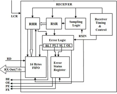
A technique presented in [5] by Himanshu Patel, Sanjay Trivedi, R. Neelkanthan and V. R. Gujraty, decreases the effects of noise appearing in the lines between UARTs, by utilizing a recursive running sum filter in the receiver. Recursive Running Sum (RRS) is a simple low pass filter. Input data signal is directly sampled with system clock and samples are accumulated over a window size. The window size is user programmable and it is set to one third of required bit period. The intermediate data bit is decoded using magnitude comparator and a majority voter is used to decode actual data bit from three intermediate data bits. Other advantage of this architecture is that baud rate is decided by the window size so there is no need of any external “timer module” which is normally required for standard UARTs. Naresh Patel, Vatsalkumar Patel and Vikaskumar Patel [3] have proposed architecture of UART using the Status register which indicates parity error, framing error, overrun error and break error during the data reception. The error logic block in the receiver as seen in Fig.4, handles four types of errors. PL bit will be set if the received parity does not match with the parity generated from data bits which indicates that parity error occurred. SL bit is set if frame error occurs when receiver fails to detect correct stop bit or when 4 samples do not match. OL bit is set when overrun error occurs if the receiver FIFO register is full and other data arrives at the RHR (receiver hold register). BL bit is set when there is a break in received data and break error occurs i.e. if the RXIN pin is held low for longer time than the frame time. [3]
Fig. 4. UART Receiver block with Error Status Register
An Enhanced UART [9] presented by R. Gallo, M. Delvai, W. Elmenreich, and A. Steininger is based on adding one over-sampler circuit to the UART architecture. Due to this, the reception line is sampled 16 times faster than usual. These samples are then voted to select the bit value. Wilfiied Elmenreich and Martin Delvai [7] have studied common timing problems with standard UARTs and imprecise oscillators and presented a calculation of upper bound for the timeliness of UART. This guarantees that a UART frame stays within its given time slot. They have studied the timing properties of a UART communication. As the baud rate of a UART is usually configured by integer values - the arithmetic rounding error leads to baud rate deviations. The architecture of common UARTs furthermore lead to intrinsic delays at the sending UART. Furthermore one has to regard the qualities of the clocks of the communication partners. Due to these factors, five timing deviations were observed: (i) Arithmetic error in baud rate setting ;(ii) send jitter problem ;(iii) clock drift ; (iv) Clock offset and (v) Signal runtime .
The condition for a successful and correct communication is given in Equation1, where n is the number of bits in a frame including the start, stop and parity bits:
< ……….. (1)
Where BR: Baud Rate.
The authors have come up with two conditions that have to be fulfilled for correct transmission: (1) Inter-Slot Condition: The UART frame must not exceed the boundaries its assigned time slot.
(2) Intra-Slot Condition: The baud rate difference between transmitter and receiver must be low enough, so that transmitted messages can be decoded correctly by the receiver.
ISSN(Online): 2320-9801
ISSN (Print) : 2320-9798
International Journal of Innovative Research in Computer
and Communication Engineering
(An ISO 3297: 2007 Certified Organization)
Vol. 4, Issue 3, March 2016
Advanced Encryption Standard (AES) algorithm in the UART module. Their proposed architecture implements AES-128 algorithm that encrypts the data before transmission through UART transmitter and decrypts after receiving the data at UART receiver module. In this work, encryption was carried out by AES-128 and decryption using iterative architecture.
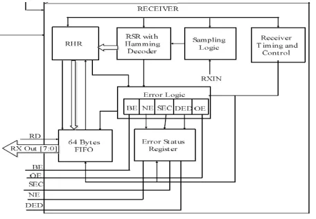
Sindhuaja Muppalla and Koteswara Rao Vaddempudi [5] have implemented the Extended Hamming codes which have forward error correction (FEC) capability. The UART designed includes (8,4) extended hamming code called SEC-DED code that can correct upto one error and detect upto two errors. This improves the noise immunity of the system hence optimizing the error free reception of data. The design circuit configuration allows two operating modes. One is the normal mode in which one parity bit is added for one bit error detection and the second mode is error correction where single error can be corrected and double error can be detected. The encoder at the transmitter takes 4 data bits giving out 8 bits consisting of the 4 data bits followed by 4 parity bits which are redundant and are called Hamming bits. Hamming decoder takes the 8 bit of which 4 bits are of data and the remaining 4 bits are check bits which are used to identify errors with the help of a syndrome generated. If the error is of only 1 bit then it is corrected and if it is of 2 bit then it can only be identified. Respective flags are generated in this process as seen in Fig. 5. The flags are set on occurrence of the conditions mentioned as follows:
BE : Break error - when break in the received data string occurs.
PE: Parity Error -when the received parity does not match the generated parity at the transmitter end. FE: Frame error - when the receiver fails to detect the correct stop bit.
OE: Overrun error- when data arrives at the receiver Hold register even though the FIFO register in receiver is full. NE: No error- when no errors occur (desired condition).
DED: Double error detected - when two bit in the data string are erroneous.
SEC- Single error corrected - when only one erroneous bit is detected and consequently corrected by changing it.
Fig. 5. UART receiver with hamming decoder and error status register.
Mohammad-Hamed Razmkhah, Seyed Ghassem Miremadi, and Alireza Ejlali in [10], have presented a compact size fault-tolerant UART called micro-FT-UART capable of correcting the transient faults occurring inside the UART. It is based on adding 3 error correction techniques to the basic structure of an UART. The three techniques are triple modular redundancy (TMR), Hamming code and a technique called correction by parity storing (CPS). The more sensitive and critical parts of the UART, such as the Finite state machine (FSM) circuit and the baud rate generator circuit are protected with the TMR technique; while the Hamming code is used in the counters, transmitter shifter and hold registers; and the CPS technique is used to correct errors occurring in the receiver shifter.
ISSN(Online): 2320-9801
ISSN (Print) : 2320-9798
International Journal of Innovative Research in Computer
and Communication Engineering
(An ISO 3297: 2007 Certified Organization)
Vol. 4, Issue 3, March 2016
to several memory positions); (ii) Recovered (the error having no functional effect and eventually disappearing); and (iii) Latent (the error not propagating to the output port, but at least one sequential element contains an incorrect value at the end of the execution). As observed by the authors, overall 8.75% errors in the UART application were failure faults, 28.28% were recovered and 62.96% were latent. The Program counter is the most critical (with maximum failure errors). The port registers produced very less failure faults, but it produced many latent faults. The proposed two SET-tolerant flip-flop architectures for transient delay sensitive paths and transient delay insensitive paths of the design were able to detect and correct the transient pulse and transient delay fault at the input of the flip-flop. These architectures were also tolerant to a Single Event Upset (SEU) caused by particle strike on the internal nodes of flip-flops in UART.
MohdYamani Idna ldris and Mashkuri Yaacob [12] have implemented the BIST (Built IN Self Test) technique in the UART design which is a method of self testing on a system on chip. A built-in-logic-block-analyser (BILBO) architecture is implemented which is a scan register that can be modified to serve as a state register, a pattern generator, a signature register, or a shift register. This technique checks if any logic errors are present in the UART. Both transmitter as well as the receiver of the UART is checked using this method. As the receiver has to wait for the signal from the transmitter, this method is time consuming but it takes advantage of 100% (internal) fault coverage.
III.CONCLUSION
A brief overview of various methods for improving reliability of serial communication through UART is presented in this paper. From the reported work, we go for designing a technique to minimize the errors in UART communication to achieve reliable data transfer. This will be carried out by exploring and combining the merits of the above mentioned methods and/or modifying the Forward Error Correcting codes.
REFERENCES
1. R. W. Hamming, “Error detecting and error correcting codes”, The Bell System Technical journal Vol. XXIX, April 1950, Vol. 2, American Telephone and Telegraph company.
2. Wayne Tomasi – “Electronic Communications systems - fundamentals through advanced”- fifth edition, Pearson Prentice Hall.
3. Naresh Patel, Vatsalkumar Patel, Vikaskumar Patel, ”VHDL Implementation of UART with Status Register”, 2012 IEEE International Conference on Communication Systems and Network Technologies, 2012.
4. Sindhuaja Muppalla, Koteswara Rao Vaddempudi,” A Novel VHDL Implementation of UART with Single Error Correction and Double Error Detection Capability”, SPACES-2015, Dept of ECE, KL UNIVERSITY.
5. Himanshu Patel, Sanjay Trivedi, R. Neelkanthan, V. R. Gujraty , "A Robust UART Architecture Based on Recursive Running Sum Filter for Better Noise Performance", Held jointly with 6th International Conference on Embedded Systems, 20th International Conference on VLSI Design, pp. 819-823, Jan. 2007.
6. V.C. Srinivas, S.K. Bhowmick, S.G. Krishna, and P. Saharia, “A VLSI System-on-a-chip (SoC) for Digital Communications”, International Conference on Wireless and Optical Communications Networks, April 2006.
7. Wilfried Elmenreich, Martin Delvai, “Time-Triggered Communication with UARTs”, 4th IEEE International Workshop on Factory Communication Systems, Vasteris, Sweden, August 28-30, 2002.
8. Debjani Basu, Deepak kole, Hafizur Rahaman, “Implementation of AES algorithm in UART module for secured data transfer”, 2012 International conference on Advances in Computing and Communication, IEEE, DOI 10.1109/ICACC2012.32.
9. R. Gallo, M. Delvai, W. Elmenreich, and A. Steininger, “Revision and Verification of an Enhanced UART,” IEEE International Workshop on Factory Communication Systems, pp. 315-318, Sept. 2004.
10. Mohammad-Hamed Razmkhah, Seyed Ghassem Miremadi, and Alireza Ejlali, “A Micro-FT-UART for Safety-Critical SoC-Based Applications”, 2009 International Conference on Availability, Reliability and Security, IEEE DOI 10.1109/ ARES.2009.43 pp.316-321. 11. Sijoy Johnson, N. Kumaresan, Manu Poulose, ”A Special Method for Analysing and Correction of Set Effects in PIC Microcontroller”,
International Journal of Soft Computing and Engineering (IJSCE) ISSN: 2231-2307, Volume-2, Issue-3, July 2012, pp. 339-342. 12. Mohd Yamani Idna ldris and Mashkuri Yaacob, "A VHDL implementation of BIST technique in UART design", 2003 Conference on