University of Windsor
University of Windsor
Scholarship at UWindsor
Scholarship at UWindsor
Electronic Theses and Dissertations
Theses, Dissertations, and Major Papers
2017
A Multibody Dynamics Model of a Motorcycle with a Multi-link
A Multibody Dynamics Model of a Motorcycle with a Multi-link
Front Suspension
Front Suspension
Changdong Liu
University of WindsorFollow this and additional works at: https://scholar.uwindsor.ca/etd
Recommended Citation
Recommended Citation
Liu, Changdong, "A Multibody Dynamics Model of a Motorcycle with a Multi-link Front Suspension" (2017). Electronic Theses and Dissertations. 7376.
https://scholar.uwindsor.ca/etd/7376
This online database contains the full-text of PhD dissertations and Masters’ theses of University of Windsor students from 1954 forward. These documents are made available for personal study and research purposes only, in accordance with the Canadian Copyright Act and the Creative Commons license—CC BY-NC-ND (Attribution, Non-Commercial, No Derivative Works). Under this license, works must always be attributed to the copyright holder (original author), cannot be used for any commercial purposes, and may not be altered. Any other use would require the permission of the copyright holder. Students may inquire about withdrawing their dissertation and/or thesis from this database. For additional inquiries, please contact the repository administrator via email
by
Changdong Liu
A Thesis
Submitted to the Faculty of Graduate Studies
through Mechanical Engineering
in Partial Fulfilment of the Requirements for
the Degree of Master of Applied Science at the
University of Windsor
Windsor, Ontario, Canada
A Multibody Dynamics Model of a Motorcycle with a Multi-link Front Suspension
by
Changdong Liu
APPROVED BY
S. Cheng
Department of Civil and Environmental Engineering
J. Johrendt
Department of Mechanical, Automotive, & Materials Engineering
B. Minaker, Advisor
Department of Mechanical, Automotive, & Materials Engineering
Author’s Declaration of Originality
I hereby certify that I am the sole author of this thesis and that no part of this thesis has been published or submitted for publication.
I certify that, to the best of my knowledge, my thesis does not infringe upon anyone’s copyright nor violate any proprietary rights and that any ideas, techniques, quotations, or any other material from the work of other people included in my thesis, published or otherwise, are fully acknowledged in accordance with the standard referencing practices. Furthermore, to the extent that I have included copyrighted material that surpasses the bounds of fair dealing within the meaning of the Canada Copyright Act, I certify that I have obtained a written permission from the copyright owner(s) to include such material(s) in my thesis and have included copies of such copyright clearances to my appendix.
iv
Abstract
To my mother,
vi
Acknowledgements
This thesis writing is nearing its end. Looking back over the past two years, many people have given me support and made this work possible, it is hard to thank all those people enough for their contributions and advice. I am always grateful for their help.
First and foremost, my deepest gratitude to my advisor Dr. B.P. Minaker, for his excellent erudition, altruism and patience. Under his instruction and help, the last two years of my MASc career is the best experience I have ever had. I am very honored to have an advisor who gave me the freedom to explore and has inspired me to be positive and confident during my demanding MASc student life. His patience and guidance helped me to complete a number of research projects. I am often attracted by his easy to understand and interesting teaching method, which also expanded my knowledge and is very helpful in finishing my thesis. I will never be able to adequately express my gratitude.
I would like to thank my mother, and my family. With their support and encouragement, I can go further along the way of my choice. They give me selfless love; home is always my strongest shield and source of strength. I would also like to express my appreciation to all my friends; it was always a pleasure coming to work every day with such lovely and engaging people.
Contents
Declaration of Originality iii
Abstract iv
Dedication v
Acknowledgements vi
List of Tables x
List of Figures xii
List of Abbreviations xvi
Nomenclature xvii
1 Introduction 1
1.1 Background . . . 3
1.1.1 Development of the Bicycle . . . 3
1.1.2 Development of the Motorcycle . . . 7
1.1.3 Motorcycle Front Suspension . . . 12
1.1.4 Patent Search . . . 16
2 Motivation, Objectives, and Thesis Structure 20 2.1 Motivation . . . 20
2.2 Research Objectives . . . 21
2.2.1 Comparisons of Simulations and Experiment . . . 22
2.3 Thesis Structure . . . 24
CONTENTS viii
3.1.1 The Geometry of Motorcycles . . . 28
3.1.2 Kinematics of the Steering Mechanism . . . 30
3.1.3 Roll Motion and Steering . . . 32
3.2 Out-of-plane Modes . . . 33
3.3 In-plane Modes . . . 35
3.3.1 In-plane Dynamics Model . . . 35
3.4 Front Suspension Structure and Characteristics . . . 38
3.5 Motorcycle Tires . . . 43
3.6 Multibody Dynamics . . . 47
3.6.1 Model in EoM Software . . . 48
3.6.2 Model in Altair MotionView® . . . 51
3.7 Generation of a Random Road . . . 53
4 Simulation Results 55 4.1 Kinematics Simulation . . . 55
4.2 Tire Test . . . 57
4.3 Out-of-plane Simulation . . . 59
4.3.1 Unforced Straight Running Simulation . . . 59
4.3.2 Forced Straight Running Simulation . . . 66
4.4 In-plane Simulation . . . 69
4.4.1 Braking Simulation . . . 70
4.4.2 Plank Road Simulation . . . 78
4.4.3 Random Road Simulation . . . 80
5 Discussion of Results 96 5.1 Model Assesment . . . 96
5.1.1 Caster Angle and Trail . . . 97
5.1.2 Motorcycle Tire . . . 97
5.2 Out-of-plane Simulation Analysis . . . 97
5.2.1 Unforced Straight Running Simulation Analysis . . . 98
5.2.2 Forced Straight Running Simulation Analysis . . . 102
5.3 In-plane Simulation Analysis . . . 106
5.3.1 Braking Simulation Analysis . . . 106
5.3.2 Plank Road Simulation Analysis . . . 112
6 Conclusions, Recommendations, and Contributions 122
6.1 Conclusions . . . 122 6.2 Recommendations . . . 123 6.3 Contributions . . . 124
References 127
Appendix A 131
A.1 Matlab®Codes of Random Road . . . 131 A.2 Matlab®Codes of Power Spectral Density . . . 133
Appendix B 134
B.1 Eigenvalues, Natural Frequency, Damping Ratio of Telescopic Front Suspension at5m/s . . 134
B.2 Eigenvalues, Natural Frequency, Damping Ratio of Telescopic Front Suspension at10m/s . . 135
B.3 Eigenvalues, Natural Frequency, Damping Ratio of Telescopic Front Suspension at40m/s . . 137
B.4 Eigenvalues, Natural Frequency, Damping Ratio of Multi-link Front Suspension at5m/s . . 138
B.5 Eigenvalues, Natural Frequency, Damping Ratio of Multi-link Front Suspension at10m/s . . 139
B.6 Eigenvalues, Natural Frequency, Damping Ratio of Multi-link Front Suspension at40m/s . . 140
Appendix C 141
C.1 Braking Simulation Results with100Nm Braking Torque . . . 141
C.2 Braking Simulation Results with800Nm Braking Torque . . . 144
x
List of Tables
3.1 Degrees of freedom of the basic motorcycle model . . . 27
3.2 Degrees of freedom of the advanced motorcycle model . . . 27
3.3 Parameters of180/55tire . . . 46
3.4 Body CG locations and mass . . . 49
3.5 Body inertia properties . . . 49
3.6 Body CG locations and mass . . . 50
3.7 Body inertia properties . . . 50
3.8 ISO Road roughness values classification . . . 54
4.1 Tire test result . . . 58
4.2 Eigenvalues of telescopic front suspension at25m/s . . . 61
4.3 Natural frequency, damping ratio at25m/s . . . 61
4.4 Eigenvalues of multi-link front suspension at25m/s . . . 63
4.5 Natural frequency, damping ratio at25m/s . . . 63
4.6 Motorcycles performance . . . 66
4.7 1Nm straight running linear analysis . . . 68
4.8 Telescopic non-linear yaw result . . . 69
4.9 Multi-link non-linear yaw result . . . 69
4.10 Telescopic braking results . . . 73
4.11 Multi-link braking results . . . 74
4.12 Caster angle and trail, telescopic suspension . . . 77
4.13 Caster angle and trail, multi-link suspension . . . 78
5.1 Frequency of bounce and pitch . . . 101
5.2 Frequency of wobble and weave modes . . . 101
5.3 Vertical force . . . 110
5.4 10m/s frame height . . . 114
5.6 10m/s pitch angle . . . 116
5.7 30m/s pitch angle . . . 116
5.8 10m/s suspension travel . . . 118
5.9 30m/s suspension travel . . . 118
B.1 Eigenvalues of telescopic front suspension at5m/s . . . 134
B.2 Natural frequency, damping ratio at5m/s . . . 135
B.3 Eigenvalues of telescopic front suspension at10m/s . . . 135
B.4 Natural frequency, damping ratio at10m/s . . . 136
B.5 Eigenvalues of telescopic front suspension at40m/s . . . 137
B.6 Natural frequency, damping ratio at40m/s . . . 137
B.7 Eigenvalues of Multi-link front suspension at5m/s . . . 138
B.8 Natural frequency, damping ratio at5m/s . . . 138
B.9 Eigenvalues of Multi-link front suspension at10m/s . . . 139
B.10 Natural frequency, damping ratio at10m/s . . . 139
B.11 Eigenvalues of Multi-link front suspension at40m/s . . . 140
xii
List of Figures
1.1 Kinematic structure of a motorcycle . . . 1
1.2 Schematic diagram of the multi-link front suspension bike . . . 2
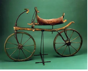
1.3 The draisine, or running machine . . . 3
1.4 Velocipede by Pierre Michaux et Cie . . . 4
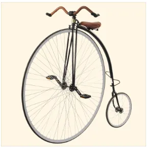
1.5 Penny farthing, or ordinary . . . 5
1.6 Eigenvalues vs speed . . . 6
1.7 Sylvester Roper steam motorcycle . . . 8
1.8 Daimler petrol-powered motorcycle . . . 9
1.9 The Hildebrand and Wolfm¨uller motorcycle . . . 9
1.10 Suzuki®GSX-R1000 . . . 10
1.11 Tommy Smith riding . . . 11
1.12 Hub-center steering . . . 12
1.13 Springer forks . . . 13
1.14 Upside-down forks . . . 13
1.15 Telelever suspension . . . 14
1.16 Doulever forks . . . 15
1.17 Big Piston suspension . . . 15
1.18 Alternate front suspensions . . . 16
1.19 EU patent No.07122393.7 . . . 17
1.20 US patent No.6, 349, 784 . . . 18
1.21 US patent No.8, 851, 221 . . . 18
2.1 Schemes of telescopic forks . . . 20
2.2 Model validation . . . 23
3.1 Geometry of a motorcycle . . . 28
3.2 Positive trail . . . 29
3.4 The steering mechanism . . . 31
3.5 Motorcycle in a curve . . . 32
3.6 Capsize . . . 34
3.7 Wobble . . . 34
3.8 Weave . . . 35
3.9 The basic model . . . 36
3.10 The bounce and pitch model . . . 37
3.11 The four degrees of freedom model . . . 38
3.12 Telescopic fork structure . . . 39
3.13 Reduced stiffness . . . 40
3.14 Multi-link front suspension I . . . 41
3.15 Multi-link front suspension II . . . 42
3.16 Multi-link front suspension III . . . 43
3.17 Tire and road . . . 43
3.18 The Magic Formula graph . . . 45
3.19 180/55tire lateral force results . . . 46
3.20 Telescopic front suspension motorcycle . . . 51
3.21 Multi-link front suspension motorcycle . . . 52
4.1 The simple3D model . . . 56
4.2 The caster angle and trail . . . 56
4.3 Tire lateral force . . . 57
4.4 Tire test result . . . 59
4.5 Telescopic eigenvalues vs speed . . . 60
4.6 Multi-link eigenvalues vs speed . . . 62
4.7 Free response at40m/s, telescopic suspension . . . 65
4.8 Free response at40m/s, multi-link suspension . . . 65
4.9 Response to50Nm1Hz steer torque, telescopic suspension I . . . 67
4.10 Response to50Nm1Hz steer torque, telescopic suspension II . . . 67
4.11 Response to50Nm1Hz steer torque, multi-link suspension . . . 68
4.12 Euler parameters principle line . . . 70
4.13 Forward velocity,500Nm braking torque . . . 71
4.14 Euler parameter𝐸2,500Nm braking torque . . . 72
4.15 Motorcycle height,500Nm braking torque . . . 73
4.16 Multi-link caster angle test model . . . 75
4.17 Multi-link trail test model . . . 75
LIST OF FIGURES xiv
4.19 Trail,500Nm braking torque . . . 77
4.20 Plank road definition . . . 78
4.21 Pitch angle of plank test . . . 79
4.22 Frame height of plank test . . . 79
4.23 Suspension travel of plank test . . . 80
4.24 Random road classification . . . 81
4.25 10m/s telescopic level6random road contact force . . . 82
4.26 10m/s multi-link level6random road contact force . . . 82
4.27 Level3random road . . . 83
4.28 10m/s level3frame height . . . 84
4.29 10m/s level3pitch angle . . . 84
4.30 10m/s level3suspension travel . . . 85
4.31 Level4random road . . . 86
4.32 10m/s level4frame height . . . 86
4.33 10m/s level4pitch angle . . . 87
4.34 10m/s level4suspension travel . . . 87
4.35 Level5random road . . . 88
4.36 10m/s level5frame height . . . 88
4.37 10m/s level5pitch angle . . . 89
4.38 10m/s level5suspension travel . . . 89
4.39 30m/s telescopic level5random road contact force . . . 90
4.40 30m/s multi-link level5random road contact force . . . 91
4.41 30m/s level3frame height . . . 92
4.42 30m/s level3pitch angle . . . 92
4.43 30m/s level3suspension travel . . . 93
4.44 30m/s level4frame height . . . 94
4.45 30m/s level4pitch angle . . . 94
4.46 30m/s level4suspension travel . . . 95
5.1 Theoretical unforced straight running result . . . 98
5.2 Telescopic suspension linear and non-linear result . . . 103
5.3 Multi-link suspension linear and non-linear result . . . 103
5.4 Telescopic suspension non-linear result . . . 104
5.5 Multi-link suspension non-linear result . . . 104
5.6 Braking stop time . . . 106
5.7 Braking pitch angle . . . 107
5.9 500Nm telescopic vertical forces . . . 109
5.10 500Nm multi-link vertical forces . . . 109
5.11 Braking caster angle . . . 111
5.12 Braking trail . . . 112
5.13 30m/s level3frame height difference . . . 115
5.14 30m/s level4pitch angle difference . . . 117
5.15 30m/s level4suspension travel difference . . . 119
5.16 30m/s level4tire compression . . . 120
5.17 30m/s level4tire compression difference . . . 120
6.1 Performance assessment method . . . 125
6.2 Comparison method . . . 126
C.1 Forward velocity,100Nm braking torque . . . 141
C.2 Euler parameter𝐸2,100Nm braking torque . . . 142
C.3 Motorcycle height,100Nm braking torque . . . 142
C.4 Caster angle,100Nm braking torque . . . 143
C.5 Trail,100Nm braking torque . . . 143
C.6 Forward velocity,800Nm braking torque . . . 144
C.7 Euler parameter𝐸2,800Nm braking torque . . . 144
C.8 Motorcycle height,800Nm braking torque . . . 145
C.9 Caster angle,800Nm braking torque . . . 145
xvi
List of Abbreviations
All abbreviations used in this work are described in this section.
Abbreviations
Abbreviation Meaning
Matlab® Matrix Laboratory software URB Unridable Bicycle
TiN A Chemical Element EoM Equation of Motion
BMW® Bavarian Motor Works (the German manufacturer)
CAE Computer Aided Engineering DAE Differential Algebraic Equation ODE Ordinary Differential Equation CG Center of Gravity
RBT Roller Bench Test
SAE Society of Automotive Engineers PSD Power Spectral Density
ISO International Standard Organization DOF Degree of Freedom
CAD Computer Aided Design
3D Three Dimensional
Nomenclature
Mathematical notation throughout this work is listed below.
Coordinate systems
Label Description
⟮𝑃𝑟, 𝑥, 𝑦, 𝑧⟯ Mobile triad with the origin in the rear contact point𝑃𝑟, according to SAE J670
𝑥 Forward and parallel to the longitudinal plane of symmetry 𝑦 Lateral on the right side of the motorcycle
𝑧 Downward with respect to the horizontal plane ⟮𝐴𝑟, 𝑋𝑟, 𝑌𝑟, 𝑍𝑟⟯ Triad attached to rear frame
𝑎1 Parallel to𝑥axis
𝑎2 Parallel to𝑦axis
𝑎3 Parallel to𝑧axis
Kinematics and dynamics parameters
Label Description
𝑉 Forward velocity 𝜉 Steering ratio 𝛿 Steering angle
𝛥 Kinematic steering angle 𝛥∗ Effective steering angle
NOMENCLATURE xviii
𝛺 Yaw angular velocity about the𝑧axis 𝑓 Frequency
𝑓p Natural frequency of pitch vibration
𝑓b Natural frequency of bounce vibration
𝑉slide Slippage velocity
𝜔f Front wheel rolling angular velocity
𝑀 Matrix of mass and inertia terms 𝑞 Generized coordinate
𝑓 Applied forces 𝜙 Constraint vector 𝜆 Lagrange multiplier
Motorcycle parameters
Label Description
𝑎 Mechanical trail (trail) 𝑎n Normal trail
𝑏 Longitudinal distance from rear axis to the motorcycle mass center 𝑏n Normal rear trail
𝑐 Viscous damping coefficient of suspension
𝑑 Fork offset: distance from the center of the front wheel to the steering
axis
ℎ Height of motorcycle mass center
𝐼yG Moment of inertia of motorcycle about the𝑦axis through its center of mass (pitch inertia)
𝑘 Suspension stiffness 𝐿 Swinging arm length 𝑚 Motorcycle mass
𝑝 Wheelbase
𝑃 Tire contact point with the ground 𝐺 Motorcycle center of mass
𝛥h Lowering of the steering head
𝜀 Caster angle
𝛽 Roll angle of the front frame (camber angle of the front wheel) 𝜂 Chain angle respect to the ground plane
Front frame parameters
Label Description
𝑏f Distance of the mass center of front frame from steering axis
ℎf Distance of the mass center of front frame from the line passing through the rear wheel center and perpendicular to the steering axis
𝐺f Mass center of front frame
𝑘f Effective (reduced) front suspension stiffness
𝑚f Front unsprung mass
𝑀f Front frame mass
𝑦 Travel distance of front wheel along front suspension sliders 𝛥y Deformation of front suspension springs due to preload
Forces and Moments
Label Description
𝑁s Static load on the wheel
𝑁 Dynamic load on the wheel
𝑁a Normalized dynamic load on the wheel: ratio of the dynamic load to the motorcycle weight
𝑁tr dynamic load transfer
𝐹 Braking force
𝐹 Lateral force on the tire 𝑀X Overturning moment
𝑀Y Rolling resistance moment
𝑀Z Yawing moment
𝑀t Twisting moment
𝜇 braking/driving force coefficient (normalized longitudinal force): ratio
NOMENCLATURE xx
Tires and wheels
Label Description
𝑎t Tire trail
𝑑 Rolling friction parameter 𝑓w Rolling resistance coefficient
𝑅 Outside radius of the tire
𝜌 Radius of torus revolution of the tire 𝑡 Radius of cross section of the tire 𝐿 Relaxation length of the tire 𝑘p Radial stiffness of the tire
𝑘s Lateral stiffness of the tire
𝐾k Longitudinal slip stiffness of the tire
𝐾φ Camber (roll) stiffness of the tire
𝑅o Effective rolling radius
𝜆 Sideslip angle of the tire
Random road parameters
Label Description
𝐿 Length of road profile 𝑥 Abscissa variable from0to𝐿 𝛥n Frequency band
𝐵 Sampling interval
𝑛max Maximum theoretical sampling spatial frequency
𝑘 A constant value depending from ISO road profile classification 𝜑i Random phase angle following an uniform probabilistic distribution
Chapter 1
Introduction
The development of the motorcycle has been ongiong for over a century since the Hildebrand & Wolfm¨uller, the world’s first production motorcycle, came off the assembly line in1894. Nowadays, to suit lots of different
purposes, there is a variety of models of motorcycle available, such as cruisers, sport bikes, tourers, and so on. Joining a motorcycle club or attending motorcycle rallies also has become part of daily life for some people. At the same time, the rider not only needs a comfortable riding experience, but also pursues the sense of freewheeling handling. Thus, scholars have never stopped the pace of innovation and research on motorcycles. The most common style of motorcycle is made up of four parts. They are the rear assembly, the front assembly, the front wheel and the rear wheel. The steering axis and the two wheel axles connect these assemblies by three revolute joints as shown in Figure 1.1.
Figure 1.1: Kinematic structure of a motorcycle (reproduced from Cossalter[1])
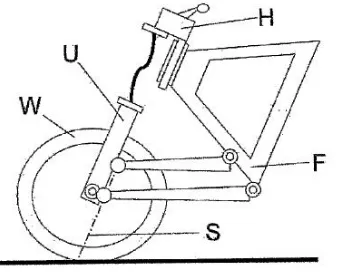
CHAPTER 1. INTRODUCTION 2 unchanged from Sharp’s model. A schematic diagram of the proposed suspension configuration is shown in Figure 1.2. In this concept, the steering and suspension kinematics are separated. The mechanism is described by Minaker and Durfy[3] as follows:
The suspension mechanism consists of four locating arms, two on each side of the cycle. The arms are mounted such that they lie in the horizontal plane, one above the other, and are symmetric across the cycle. Each arm is attached to the frame at the rear end, and to the lower fork, or front wheel carrier, at the front end. In practice, the arms would be be attached by Heim joints at both ends, but in the model, one spherical joint and one universal joint are used on each arm, to prevent the rotation of the arm around its own axis. The geometry of the arms is such that if the centreline was extended, it would intersect the axis of its opposite side counterpart at a point directly on the steer axis of the front wheel. In fact, it is the geometry of the two intersection points that defines the steer axis. In order to produce the desired geometry, the rear of the arms are spaced wider apart than the front. The upper arms are angled more than the lower, such that their intersection is further back, giving a steer axis that is inclined rearward as in a typical fork arrangement. In the model, the geometry of the arms is chosen such that the values of the effective rake and trail are identical to the conventional fork suspension. The mass and inertia values of the lower fork body are maintained to represent the wheel carrier. The upper fork body is also maintained in the model to represent the handlebars and steering mechanism, but the translational joint representing the telescopic connection to the lower fork is removed. A telescopic steering shaft with universal joints on both ends is used to transmit the steering torque from the upper fork body to the lower fork body. In the multibody model, this shaft is represented by a constraint equation that enforces matching rotation of the upper and lower fork around the steering axis. The front suspension springs are mounted between the upper and lower fork bodies, but are modelled as using spherical joints on both ends.
1.1 Background
1.1.1 Development of the Bicycle
Dating back to over300years ago, human beings had already realized the potential of their own powered
transportation[4]. Compared to wind power and horse power, humans using their own strength were free of restrictions posed by environmental limitations and influence. There are two types of mechanism, cranks and levers respectively, which have been used to allow the rider to drive a vehicle. This mechanism can be defined only as a vehicle but not a bicycle, because these early vehicular contraptions[5] were too huge and heavy to be well used. Also, except for using two wheels, they were absolutely different than the next generation of machines.
In1817, the German inventor Baron Karl von Drais got inspiration from the ice sledge[6]. This vehicle
still cannot be described as a bicycle, because it seems just like the ice sledge with two wheels. Thus, it should be called a running machine or draisine[6]. Figure 1.3 shows the draisine from the side perspective. The seat is a long bar that looks like a saddle. During driving, the rider is able to lay his or her arm on a small stuffed rest, which is between the front handle and seat. The power of this draisine comes from the rider’s leg movement. The front wheel is steerable. To popularize his machine, von Drais traveled to many European countries. In France, his running machine had a demonstration to show its speed and obstacle performance. After that, the draisine experienced a short period of European popularity. An English designer, Denis Johnson, upgraded the draisine and began to manufacture his product, named the hobby horse, after the draisine spread to England in late1818[7]. Its boom did not last long. The absence of drive and braking
capabilities made this draisine uncomfortable to ride. Furthermore, there is almost no difference between going on foot and riding the drasine.
Figure 1.3: The draisine, or running machine (reproduced from Smithsonian National Museum[8])
CHAPTER 1. INTRODUCTION 4 on the inventor responsible. One of them is Kirkpatrick Macmillan, a Scotsman who introduced the first two wheeled pedal-drive mechanism in1840[4]. Another viewpoint is that in approximately1861, Pierre
Michaux, a French coach builder added pedals on when a rider brought him a broken draisine for repairs. This improvement resulted in a milestone machine in bicycle development, called the Michaux machine. The appearance of the Michaux machine in Figure 1.4 seems very close to a modern bicycle. The total weight of this vehicle is about60pounds. This velocipede is very famous, because it was essentially the first
time the pedal mechanism had been used on a human-propelled vehicle. This innovation greatly promoted the development of the mobility tool, although this machine was only popular for about three years. Its elimination was due to the extremely uncomfortable ride. One of the most common problems was that the rider’s legs were caught by the front wheel when cornering. To overcome this flaw, central hinged frames and rear-steering were tried, but they did not work well[9].
Figure 1.4: Velocipede by Pierre Michaux et Cie of Paris, France circa1869. (reproduced from The Online Bicycle Museum[10])
Figure 1.5: Penny farthing, or ordinary. (reproduced from UDC Penny Farthings[11])
Based on the design of the original bicycle, there were many attempts to improve its performance, which made the bicycle what it is today. Some of them had a significant role to play during the development of the bicycle. For example, the pneumatic tire was invented by John Boyd Dunlop in1899[7]. This new tire increased
the speed of the bicycle, especially after the upgrade of the Pneumatic Tyre Company, which developed a stout canvas lining for the inner surface of the tire[5]. The chain and sprocket drive system, another key innovation, improved the efficiency of the actuating unit and has continued to do so[4]. Furthermore, other inventions such as equal size wheels, lightweight stiff steel frames, caliper brakes, sprung seats, front and rear suspension systems, free-running drive hubs, and multispeed Derailleur gear trains made up the current bicycle, and also produced multiple branches, like mountain bikes and road bikes[12].
With the continuous development of bicycles, the theory and technology has also progressed during the same period. It is obvious that the mathematical model of a bicycle is a multibody system. In1869, there were
five consecutive short articles that discussed the dynamics of bicycles. A heuristic inverted-pendulum-type model was built to analyze balancing, steering and propulsion performance of the bicycle[13]. These papers had a little technical value. In fact, they only proved that rear-wheel steering was not suitable for ordinary use in a bicycle.
In1899, Francis John Welsh Whipple published a seminal paper, which is the first substantial contribution
CHAPTER 1. INTRODUCTION 6 The basic bicycle model is made up of four parts. Two of them are the front and rear wheels that are free to rotate around their axles, which are rigidly attached to the front and rear frames respectively. Each wheel is assumed to be thin and touch with the ground only at a single contact point. Also, the wheels, which are also assumed to be non-slipping, are modeled by holonomic constraints in the normal (vertical) direction and by nonholonomic constraints in the longitudinal and lateral directions[15]. The rear frame can translate in three axial directions and also has roll motion around the longitudinal axis. Nowadays, the analysis of bicycle motion usually needs to consider the aerodynamics, frame flexibility and suspension system, but it is impossible to do these analyses at the time when the original bicycle dynamics theory was born. Under the constant speed assumption, the Routh criteria was used to deduce the stability implications associated with the equation of motion[7]. The quartic equation calculation is relatively much simpler today. The dynamic properties of a forward- and reverse-running bicycle as a function of speed can be seen in Figure 1.6. This graph was produced using Matlab®software.
0 1 2 3 4 5 6 7 8 9 10
−20 −10 0 10
0
Speed [m/s]
Eigenvalue
[1/s]
Real Imaginary
Figure 1.6: Real and imaginary parts of the eigenvalues of the straight-running Whipple bicycle model as functions of speed.
Another important element of the bicycle dynamics research is the tire. The concept of the bicycle with side-slipping and force-generating tires first appeared in an article from Roland[19]. Neimark and Fufaev[20] added the pneumatic tires to the straight-running bicycle model, which was used to analyze the stability. After that, some different tire models have been proposed by Hand[21] and Schwab[22]. On the other hand, some interesting bicycle-related experiments, utilizing control theory knowledge have been developed by Astrom[23].
There is also a novel experiment worth some attention. The ‘Unridable Bicycle’ model was developed in the context of bicycle dynamics[18]. The most obvious feature of this model is the cancellation of the front wheel gyroscopic moment using a very slighlty smaller counter-rotating wheel mounted alongside the front wheel. However, a series of experiments proved that this bicycle is still very rideable and the cancellation of the gyroscopic moment did not have a significant impact. Meanwhile, this model has also been proved unstable and tested many times with three kinds of changes[18], resulting from the modification of the front-wheel radius and the magnitude and sign of the fork offset.
1.1.2 Development of the Motorcycle
The invention of motorcycles began after the development of bicycles and engines. In fact, the first motorcy-cles were merely bicymotorcy-cles with small engines thrust into the frame[24]. Nowadays, as one of the world’s most popular means of transport, the motorcycle is not the early period monster that was made of metal and solid wood; it is rich in variety, advanced technology and well-made. Comparing with other modes of transport, it has unparalleled advantages. For the businessman, it is a small investment that can deliver goods to earn money. For tourists, it is an economical, convenient and fast way to travel far away. For athletes, it is the most thrilling competition item on the sports field, the ‘nice ride’ with high-speed mechanical power. During nearly130years of development, pioneering builders have exhausted their own intelligence and created
numerous milestone achievements, leaving their name in the history books.
In1770, a French man, Nicolas Joseph Cugnot, developed and manufactured the world’s first
steam-powered tricycle, which used steam generated from a boiler in front of the vehicle to push a piston in a cylinder to drive the front wheel. This3.5km/h speed vehicle, accompanied with loud rumbling and rolling
smoke of the steam engine, indicated that human force has gradually replaced natural force to drive the beginning of the vehicle era. In1868, an American, Sylvester H. Roper, first designed and mounted a boiler
on a bike (see Figure 1.7). This steam-powered bike was also equipped with a cylinder, connecting rod, crank arm, exhaust pipe, front brake, and other devices. However, the structure of the vehicle was rough and insecure.
In1869, the French engineer Pierre Michaux and Louis Guillaume Perreaux also installed a small steam
engine that was designed and manufactured on an ‘outdated bike’ for a motorized test. This motorcycle that combined the small steam engine and bicycle actually ran about16km from Paris to Saint-Germain. This
CHAPTER 1. INTRODUCTION 8 the Copeland brothers in the United States also produced a steam bike prototype called a ‘penny-farthing’ and then made a commercial motor tricycle. In1885, Rover designed a diamond-shaped frame and chain
drive safety bike, which built a reliable foundation for the subsequent motorcycle frame and transmission system design.
Figure 1.7: Sylvester Roper steam motorcycle. (reproduced from The Smithsonian Museum[25])
Although the world’s technology pioneers designed and manufactured a variety of steam-type motor vehicles that could also run a short distance, the brake, transmission, ignition, clutch, controls, and other elements of the design of the vehicle were not reliable and safe, and did not even have modern motorcycle basic structural features. Thus, these vehicles could not be successfully mass produced. Over the years, various methods to use the steam engine to power motor vehicles were tried. However, the steam engine power was too small, and most importantly, the engine was too large and very unsafe, and could easily cause injury to the driver.
In1876, the German Dr. Nikolaus Otto made a great breakthrough in the gasoline engine structural
design, and received related patents. In1883, Dr. Otto’s student Gottlieb Daimler re-designed and created a
small gasoline engine, capable of running at700rev/min. This gasoline engine was installed between the
two wheels (see Figure 1.8). The power was transferred from the belt to the intermediate shaft and then from the gear to the rear wheel. The frame and fork were made of wood and iron pipes. The seat was made of wood and its surface was covered by several layers of leather cushions. In addition to the front and rear wheel, two small wooden wheels could also be installed on both sides of the body to enhance the stability of the vehicle. Therefore, this vehicle actually had four wheels on the ground. There were some genius designs that were used in the prototype. For example, a rotating handle with a ratchet decoupling structure was used to control the brake of the rear wheel and the clutch. On November10,1885, Daimler’s son Paul drove the
vehicle from Cannstatt to Untert¨urkheim, around9.5km. He also became the world’s first motorcycle driver.
Although the original motorcycle was very simple and crude, after100years of development, hundreds of
Figure 1.8: Daimler petrol-powered motorcycle.
(reproduced from The American Society of Mechanical Engineers[26])
In 1893, the Italian engineer Enrico Bernardi designed the world’s first motorcycle equipped with
four-stroke single-cylinder gasoline engine. In1894, the water-cooled, two cylinder horizontal parallel and
four-stroke gasoline engine with1488ml engine displacement was developed by Hildebrand and Wolfm¨ueller.
The power of this motorcycle (see Figure 1.9) was1.84kW and it was soon put into mass production, becoming
the first series production motorcycle.
Figure 1.9: The Hildebrand and Wolfm¨uller, the world’s first mass produced motorcycle (reproduced from Hemmings[27])
From the end of the19thcentury to the early20thcentury was the heyday of motorcycle innovation
development, which also laid the basis for motorcycle products. There have been many famous motorcycle factories, such as the British Invincible®and Triumph®, the Italian Biaggio®and Ducati®, the German
BMW®and Boer®, the American Harley®and the French Peugeot®. A motorcycle is a product of the times,
CHAPTER 1. INTRODUCTION 10 pedal to fix the engine in the gap. This design changed the weight distribution and reduced the height of the centre of mass. It also used an electronic ignition and jet carburetor. In the next century, most modern motorcycles imitated and evolved from the Werner brothers’ design. At the beginning of the20thcentury,
due to the lessons learned from the bicycle, the motorcycle began to enter mass production in the factory and showed its actual value. In fact, from the twenties of the20thcentury to the present, improvements
have become the main theme of the development of motorcycles.
Figure 1.10: Suzuki®GSX-R1000. This motorcycle has a maximum output power of approximately
117kW at13200rev/min. The corresponding top speed is in excess of80m/s [288km/h].
(reproduced from contramanillar.com [tr. countermeasures.com][28])
The modeling and control of a motorcycle are different from the process for a bicycle. There are three main reasons. First of all, the weight of a motorcycle is much larger than that of a bicycle; the difference is about ten times. Secondly, due to the disparate weight, the rider has a different role to play during the model building process between a motorcycle and a bicycle. Thirdly, the speed is also hugely different. Usually, the speed of a bicycle can be around20km/h. A modern motorcycle can achieve a top speed of about180km/h.
For some sport motorcycles, the speed is able to reach even220km/h. Under this speed, the modeling process
should not only consider the normal dynamics of the bicycle, but should also consider the aerodynamic force analysis.
• Must be consistent with bicycle-like behavior at low speed
• Must reproduce the autostability properties predicted by Whipple[14]
• Must reproduce the motorcycle’s inclination to wobble at intermediate and high speeds
• Must reproduce the observed high-speed weave characteristics of high-performance motorcycles Based on the ideas above, the theory of motorcycle dynamics has been perfected gradually, and some scholars have even done experimental research based on their own experience. Tommy Smith is one of them. He made several high-speed runs at the Bonneville Salt Flats in Utah. To change the load on the front wheel, he had to try some unusual riding position, e.g. as shown in Figure 1.11. In the end, he ran his motorcycle at a very high speed. The front wheel began to wobble for about three to five seconds. At224km/h, he finally
could not maintain his hold on the handlebars, to prevent himself from falling off. His injuries proved the theory that light riders might be more likely to suffer from the wobble instability.
Figure 1.11: Tommy Smith riding a modified650-cc Triumph Thunderbird at the Bonneville Salt Flats in Utah. (reproduced from D.J.N. Limebeer and R.S. Sharp[7])
After that, Limebeer, Sharp and Evangelou[29] confirmed this result by computer simulation studies. Especially in Sharp’s1971paper[30], which stated that the frequency of wobble motion is typically from7
Hz to9Hz, and acts on the steering system. It also predicted that during low speeds, the wobble mode is well
damped, but gradually tends to be lighter damped at high speeds. After Smith’s experiments, Spierings[31], and Sharp and Alstead[32] also studied the wobble motion and found that the motorcycle has a tendency to wobble at high speed. With the increasing amount of literature on motorcycle dynamics, the capsize, wobble and weave modes gradually moved up to the central role for describing motorcycle handling qualities. Most importantly, these modes relate to safety, and are connected to several high-profile accidents in the literature[29].
CHAPTER 1. INTRODUCTION 12 complex than the latter. In this thesis, based on the research results of the former, the models focused mainly on the straight running case and partly on the cornering case. Some specific theories about motorcycle dynamics will be mentioned and explained in Chapter 3.
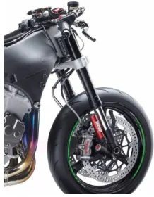
1.1.3 Motorcycle Front Suspension
When comparing with the motorcycle’s rapid technological progress, the improvement of the front suspension is not so obvious. There are mainly two basic functions of a motorcycle suspension system. One is to isolate the bumps in the road, to ensure the comfort of riders and protect passengers’ safety. The second is to provide the steering and control motions of the rider with support. The typical configuration of a modern motorcycle front suspension system is the front fork, which is laid on both sides of the front wheel. However, the real needs are much more than the ‘typical configuration’ can provide. The front suspension system not only needs to adapt to the increases in speed and weight, but also has to satisfy the demands of control quality and stability. Therefore, during the history of the motorcycle development, there have been some attempts to improve the front suspension system.
Figure 1.12: Hub-center steering mechanism. (reproduced from ISR Brakes-Sweden[34])
Inherited from the structure of the bicycle, the telescopic front fork has been used for a long time. Even now, it is still the top choice for most motorcycle makers. However, it is undeniable that the defects of this mechanism have gradually been identified by the industry. In1910, the British James Cycle Company firstly
developed the hub-center steering concept. In this structure, the entire steering mechanism is installed inside the wheel hub (see Figure 1.12). Each side of the front wheel has a connecting rod that is used to transfer the handlebar force. To be more precise, the cooperation between the two rods pushing and pulling can produce steering motion of the motorcycle.
Following the ‘hardtail’ (no rear suspension used at all) choppers popular in the1960s and1970s,
Harley-Davidson®began to equip its traditional motorcycle with a ‘springer’ style front suspension system[36], as
mechanism. Furthermore, the four-spring shock absorber system is also very interesting. These two pairs of springs are arranged along the front fork separately. During the wheel movement, the upper pair of springs and the lower pair of springs will have opposite motion, compression or stretch respectively.
Figure 1.13: Springer fork suspension.
(reproduced from ZERO Engineering original Springer fork[38])
In the late1980s, many motorcycle racing teams turned their forks ‘upside-down’, as seen Figure 1.14,
which improved their motorcycles’ handling. Upside-down forks are now the standard on many current motorcycles. Comparing to the traditional telescopic front fork, the upside-down fork structure is exactly the opposite. The inner tube is mounted on the lower front axle and the outer tube is mounted in the upper triangular clamp. There are two advantages of this arrangement. One is to reduce the unsprung mass in the suspension system, which is supposed to be light and sensitive for better handling control. The second is the increase of bending rigidity (the larger diameter outer fork tubes are used where the bending moments are highest) that also helps to improve the handling quality. This fork is used mainly for sports type motorcycles, because the cost of the upside-down fork is much more than the traditional fork.
CHAPTER 1. INTRODUCTION 14 In the early1980s, the Telelever front suspension system (Figure 1.15) was developed by Saxon-Motodd®
in Britain. After that, the Telelever is one of the signs for BMW®motorcycles. At first glance, the Telelever and telescopic fork appear very similar. In fact, these two structures are quite different.
The telescopic fork is supported by upper and lower triangular clamps, which are in turn attached to the frame by the steering head bearing. The Telelever has only one upper triangular clamp fixed to the frame by a spherical bearing. Instead of the lower triangular clamp, it uses an A-arm hinged to the frame, and fixed to the lower fork by second spherical joint. It is mechanically similar in operation to a MacPherson strut style automotive suspension, except that the A-arm is located above the wheel rather than inside as on a car. This design also allows the slide tube to be longer, that is, the overlap area between the sliding and fixed tube is increased, which helps to improve the front fork rigidity and enhance the stability.
Figure 1.15: Telelever suspension. (reproduced from BMW®Motorrad[37])
Another advantage of the Telelever is the significant reduction in diving during emergency braking, which makes the anti-lock braking system work smoother. Although the anti-lock braking system will produce a pulsating braking force, the Telelever will not let the rider feel the sense of forward decline, which also enhances stability and the rider’s ability to control the steering.
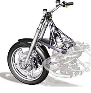
In2004, based on a design of Norman Hossack[39], BMW®developed its new front suspension named
the Duolever, seen in Figure 1.16. This new system was first mounted on the K1200S model. This suspension
is different from the telescopic or Telelever fork, and is mechanically similar to an automotive double A-arm type suspension. In high-speed emergency braking, the Duolever’s characteristics offer significant improvement in the suspension performance of the K1200S[40]. In addition, comparing with the traditional
Figure 1.16: Doulever front forks. (reproduced from Inter Cars[41])
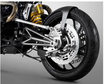
In2012, the new Honda®CBR1000RR model was launched, featuring Big Piston suspension technology.
The Big Piston suspension system, shown in Figure 1.17 has a built-in large-capacity damping chamber that significantly reduces the resulting hydraulic pressure during the extension of the fork. The manufacturer claims that this makes the whole damping process smoother, while at the same time, providing the rider with rich and delicate feedback. Also, under emergency braking, the rider feels more stability at the front end.
Figure 1.17: Big piston suspension system. (reproduced from Sport Rider[42])
CHAPTER 1. INTRODUCTION 16 In2016, the Kawasaki®ZX-10R model was launched. Its front wheel is equipped with the Free Balanced
Front fork, which is directly imported from the World SuperBike racing series and is the first use on a production motorcycle. In a conventional fork, cavitation is often caused by rapid pressure fluctuations during the hydraulic balance, which also results in poor performance of the suspension. The Free Balanced Front suspension can help suppress fluctuations in pressure balance. It can also improve the riding comfort by providing independent adjustment of compression and rebound damping.
Throughout the development of the motorcycle front suspension, there were a variety of attempts for modfiying the structure that show the designers’ wisdom and innovation. Mavroudakis and Eberhard[43] provide a sample of some of the different suspension configurations that have been attempted. They also note that advanced material coatings, such as TiN or carbon matrix composites, have also been applied in an attempt to reduce sliding friction.
Figure 1.18: Alternate front suspensions (reproduced from Mavroudakis and Eberhard[43])
However, looking at the motorcycles on the market right now, the telescopic front suspension still holds the majority of the market, although customers already know it has some drawbacks. This also means that these series of studies and innovations have not fundamentally solved all the problems of the front suspension. Therefore, in this thesis, a novel multi-link suspension will be studied for the front assembly of the motorcycle. Meanwhile, there are already many related patents (Figure 1.18) describing improvements that aim to resolve these defects, some which will be mentioned below.
1.1.4 Patent Search
First of all, the patent named ‘Motorcycle with air suspensions’ was invented by Calzavara[44] and authorized by the European Patent office. The purpose of this invention is to make the suspension easier to be adjusted to achieve the best riding position, and which, at the same time, is cheap and easy to produce. As can be seen in Figure 1.19, this mechanism is actually a whole motorcycle structural design. This section mainly describes the peripheral mechanism around the front wheel, because this thesis is working for the improvement of the motorcycle front suspension. There are in total three connecting rods on one side of the front wheel. Two of them play a connection and support role between the motorcycle body frame and front wheel. The other one works for the motorcycle steering motion. This mechanism separates the steering and damping functions of the front suspension[44]. For the front wheel connecting structure, it looks very similar with the novel multi-link suspension in this thesis. However, at the connection point of the mechanism, they are totally different. In this patent, all of the connection joints are revolute joints (i.e. hinges). But in the novel multi-link suspension, they are spherical joints (i.e., ball joints). Most importantly, the steering motion is realized by the push and pull forces, which act on the steering linkage rod. This is also different with the design in this thesis. In general, the idea of this patent is very novel, especially the way it connects the front and rear wheel suspension mechanisms using the linkage adjustment of the suspension system.
Figure 1.19: Motorcycle with air suspensions. (reproduced from Calzavara[44])
CHAPTER 1. INTRODUCTION 18
Figure 1.20: Motorcycle provided with a steering hub. (reproduced from Van der Heide[45])
As can be seen from Figure 1.20, similar to the previous patent, it also uses a linkage mechanism to eliminate the above drawbacks. This mechanism is able to fix the position of the front wheel. Moreover, it is supposed to reduce vibration of the suspension. Notably, a revolute joint is specified as the connector for these rods, which limits the rod to rotate around a fixed axis. Comparing with the novel multi-link suspension studied in this thesis, there are two main differences. First, the steering mechanism is fundamentally different. Another distinction is that the linkage mechanism of this patent is only set on one side of the front wheel. In general, this patent takes interesting improvements for the hub-center steering mechanism. It also implies that the link mechanism can play an effective role in maintaining the front wheel stability.
Figure 1.21: MOTORCYCLE. One of the fifteen different possible topologies (reproduced from Glover[46])
it appears that the concept developed here is novel and unique, and has the strong possibility of receiving a patent.
20
Chapter 2
Motivation, Objectives, and Thesis
Structure
2.1 Motivation
Imagine a rider on a motorcycle, finding a turn up ahead. To decrease the speed of the motorcycle, the rider needs to apply the brake on the front wheel. At the same time, the front forks compress and motorcycle pitches forward, which results in the rider feeling like they are being thrown slightly forward. As the rider reaches the turn, and releases the brake, the bike wobbles gradually. If there is some emergency situation during the turn, the rider will immediately grab the brakes in order to do an emergency stop. The motion of the motorcycle and the feeling of rider will become more intense than the usual braking, which will make the steering heavy and the wheel start to shudder[24]. The rider finally stops the motorcycle and has a bad experience. In reality, many of these problems come from the usage of telescopic front forks on modern motorcycles.
The main functions of a motorcycle’s front suspension are: to guide the front wheel, to steer, to spring, to dampen, and to provide support under braking[50]. It is well known that the telescopic front fork (Figure 2.1) is the most widely used front suspension for motorcycles, because the first motorcycle was a bicycle with a small engine mounted into the frame. However, there are a number of shortcomings inherent in this design. First of all, between the sliding parts of this suspension, the static friction cannot be eliminated. Because telescopic forks are mechanically prismatic joints, there is significant sliding contact, and the sliding friction is increased when the prismatic joint flexes under bending loads. This friction results in low work efficiency of the front suspension when the motorcycle is running with small road excitations. To resolve this problem, one significant advancement to the state-of-the-art was introduction of the ‘upside-down’ forks, where the outer tube of the telescopic joint was placed above the inner tube, to better resist the bending moments. Also, advanced material coatings, such as TiN or carbon matrix composites, were applied in an attempt to reduce friction, but the intrinsic disadvantage is still present[43].
Most importantly, as the fork structure was inherited from the bicycle, it did not adapt to the gradually increasing speed, mass, and tire width of the motorcycle. Fundamentally, the telescopic fork cannot separate steering and braking forces. As a result, the long and thin fork tubes need to carry forces through the steering head bearings to transfer them to the frame. The whole fork and wheel assembly must be steered in and out of turns. Thus, the increased loads present in a motorcycle requires that fork legs must be strengthened, bearing areas widened and frame structures enlarged in an ever-downward spiral towards heavier and bulkier systems[24].
2.2 Research Objectives
After searching the related literature and understanding the current situation regarding motorcycle dynamics, the objectives for this thesis are set as follows:
• Building linear and non-linear dynamic models for both conventional and multi-link front fork motorcycles.
• Building open loop simulations of the out-of-plane modes (both conventional and multi-link models) • Building open loop simulations of the in-plane modes (both conventional and multi-link models) • Collecting and preparing the data from the simulation above
CHAPTER 2. MOTIVATION, OBJECTIVES, AND THESIS STRUCTURE 22 There are some points that should be mentioned for these objectives. Firstly, the EoM open-source software developed by the University of Windsor Vehicle Dynamics and Control Research Group will be used for the linear model analysis. MotionView®, a commerical code developed by Altair Engineering, Inc. and released as part of their HyperWorks suite of CAE tools, will be used for the non-linear model analysis. This means that four models will be be built in this project (both linear and non-linear variations of the both the fork and multi-link models). Secondly, in an open loop vehicle simulation, both the rectilinear and steady turning motions are mainly explored by adding predetermined applied forces or torques to appropriate bodies. In a closed loop simulation, a driver model needs to be built, which is based on a series of driver’s correction parameters and algorithms. Finally, the appearance of capsize, weave, and wobble modes will be one of the means used to assess the performance of these models.
2.2.1 Comparisons of Simulations and Experiment
In this thesis, there are two software tools used for the linear and non-linear analysis, respectively. To conduct the linear analysis, the equations of motion are first generated using the EoM software. The EoM software is a programming package based on the Matlab®language. It is able to generate the equations of
motion for a three dimensional mechanism composed of rigid bodies, and coupled by either rigid or flexible connectors. The EoM software returns a series of matrices, which constitute the main body of the equations of motion. The EoM software also uses these resulting equations to do some typical linear analysis, including eigenvalues and frequency response. In this project, the EoM software will be used to build models of both styles of motorcycles, first using the conventional fork suspension, followed by the multi-link style.
For the non-linear analysis, Altair MotionView®, a commercial software for multibody dynamics, is available for this project. The modeling task will be conducted in MotionView®, and then the simulation conducted using the MotionSolve®engine. To be more precise, to predict forces, kinematics and dynamics of motion, MotionSolve® can accurately simulate any mechanical system. The mechanical system may
consist of rigid or structurally flexible bodies connected by various kinds of kinematic constraints and flexible connectors. Environmental forces and motion excitations drive the motion of the entire system[47]. MotionSolve®provides new and advanced options for calculating mechanical system behavior. A choice
of six solvers is available to tackle a large variety of dynamics problems. The solvers include implicit/ex-plicit, stiff/non-stiff, and differential algebraic equation/ ordinary differential equation (DAE/ODE) based algorithms[47]. More detailed software and modeling content will be described in Chapter 3.
to simulate system performance and is more likely to assess the actual situation, as was the MotionView® software that was used in this thesis.
There are already many studies about comparisons of multibody dynamics simulations and experiments, e.g., the results published by Ardiri et al[48] attest to the validity of the simulation for vehicle dynamics modelling. In this article, the MotionView®software was used to build a scooter model. The scooter is a
motorcycle with step through frame and a platform for the rider’s feet. The reference vehicle modeled in this paper is similar to the models in this thesis. The model structure of the scooter is based on the Roller Bench Test (RBT) experiment. The RBT experiment is a common test widely used inside motorcycle companies[48]. A standard implementation of this experiment has not been defined. Therefore, this article mainly refers to the RBT experiment used by the well known Italian scooter manufacturer Piaggio® & C. SpA, where the vehicle is positioned above two rolling drums and provided with suitable obstacles[49]. A model of the scooter comprised of three parts is described. First, a multibody model representing the frame and suspension components is used; secondly, a spring and hydraulic damper model is developed; finally, a pnuematic tire model is added. The construction of the entire model pursues reality as closely as possible. A numerical analysis is conducted using MotionView®, and compared with experimental results based on the
roller bench test.
Figure 2.2: Model validation.
The suspension stroke time histories in the numerical analysis and experimental results The red line presents the numerical results. The blue line presents the experimental results.
(reproduced from Ardiri[48])
CHAPTER 2. MOTIVATION, OBJECTIVES, AND THESIS STRUCTURE 24 suspension does not oscillate around the static equilibrium point. Furthermore, the reported discrepancy between experimental and simulation results is less than5%[48], meaning that the agreement of the results
concerning this effect are fairly good too. Overall, this paper provides some evidence that the simulation tools are capable of accurately predicting the trends and relative merit of various motorcycle suspension configurations. As a result, the simulation results developed in this thesis will be taken as acceptably close to reality such that no experimental results are strictly neceessary.
2.3 Thesis Structure
This thesis studies the performance of a proposed innovative multi-link front suspension design to potentially improve ride quality and handling performance. In this section, brief description of each chapter will be given, to help in understanding structure of this thesis.
Chapter 1 introduces the history of development from bicycle to motorcycle. The relevant theories are also explained. After that, in order to cater to the main topic of this thesis, several common motorcycle front suspension systems are introduced. Most importantly, the innovation structure of multi-link front suspension motorcycle is demonstrated. Furthermore, due to a related patent application, a variety of concepts are mentioned in these patents are described.
Chapter 3 expounds on the theoretical basis of this thesis. The kinematics of motorcycles is first explained and then some parameters related to the front suspension assembly of the motorcycle are described. In the next part, the out-of-plane modes, three typical motorcycle dynamics motions are introduced. In-plane modes are explained and their relevance to the front suspension system is also mentioned. The structure and characteristics of a typical motorcycle front suspension are demonstrated. Moreover, some changes of front assembly caused by the new design are explained. The ‘Magic Formula’ tire model is described. Afterwards, this section describes the theory of multibody dynamics that are relevant for the modelling. The two software tools used for the modelling are described, and some model parameters are also given in this chapter.
Chapter 4 shows the simulation results of both telescopic and multi-link front suspension motorcycle models. The first result is the verification of multi-link front suspension structure and tire model. The second result is the comparsion of the linear and non-linear models, through the out-of-plane motions. Also, the results of unforced and forced straight running performance for these two kinds of motorcycles are displayed. After that, the results of in-plane simulation can be seen in this section, which shows the performance of both telescopic and multi-link front suspension systems.
running performance of these two kinds of motorcycles are compared. For the in-plane simulation results, all analysis and discussion focus on the performance of front suspension system. This is also the main topic of this thesis. Its conclusion determines whether the new front suspension design meets the expectations for ride quality and handling performance.
26
Chapter 3
Motorcycle Dynamics and Modeling
In this chapter, the theory of motorcycle dynamics will be described. First of all, it is important for this thesis to introduce the kinematic study of motorcycles, because it relates to the dynamic behavior. It is the basic knowledge of this thesis. Secondly, based on the kinematic structure of the motorcycle, the dynamic motion of motorcycles need to be analyzed. According to Dr. V. Cossalter, a widely recognized researcher on motorcycle behavior and performance, as described in his text Motorcycle Dynamics[1], there are two basic categories of motorcycle motion: rectilinear, and steady turning. The study of rectilinear motion relates to braking and acceleration behavior under different road conditions. It is possible for the motorcycle to have some unsafe situations, such as forward overturning or wheelying, during rectilinear motion. In steady turning motion, a zero, positive or negative value of torque may be applied to the handlebars, with the aim of maintaining equilibrium of the motorcycle. To better control the motorcycle in a turn, the rider usually moves their leg and body towards the interior in the saddle to reduce the roll angle of the motorcycle. On the other hand, based on the two motions, the free-modes of the motorcycle can be grouped as in-plane modes and out-of-plane modes[51]. The former includes the pitch, bounce, and front and rear wheel hops, with motion fully in the motorcycle symmetric plane. The other modes are capsize, weave, and wobble. Usually, information regarding riding safety, handling capabilities, and riding comfort can be obtained from the modal and stability analysis. After that, due to the difference between the automotive and motorcycle tires, the characteristics of the motorcycle tire will be introduced. In the next section, it is also necessary to explain the theory of multibody dynamics; the simulation process in this thesis directly uses multibody dynamic analysis tools. Finally, the multibody modeling process for both the linear and non-linear analysis will be described, relating to the two software tools that were mentioned in Chapter 1.
3.1 Kinematics of Motorcycles
rear wheel. As can be seen from Figure 1.1, three revolute joints connect these four rigid bodies. Each body has six degrees of freedom and every revolute joint imposes five constraints. Moreover, in this structure, the lowest point on each wheel must remain in contact with the ground. As a result, the total number of degrees of freedom is three. Table 3.1 shows the details of this value.
Rigid Bodies Constraints
Revolute joints Wheel-ground constraints Rear frame Steering Front Front frame Front wheel Rear Front wheel Rear wheel
Rear wheel
4 × 6 = 24 3 × 5 = 15 2 × 3 = 6
Table 3.1: Degrees of freedom of the basic motorcycle model
These three degrees of freedom represent three most important movements of motorcycle. The first movement is that each wheel rotates around its axle, which creates the motorcycle forward motion. The second movement is the roll motion around the straight line that passes through the ground contact points of both front and rear wheels. The third movement is the steering rotation, which is the front wheel rotates around the axis passing through the steering head bearing. All three major movements combine with in various combinations to produce an infinite number of possible time history trajectories. The rider uses these to create their own riding style. However, it is worth noting that in this original kinematic structure of the motorcycle, the tire slippage movement is ignored, but in reality, this slippage movement has a crucial role to play in the motorcycle dynamic analysis. Also, due to the topic of this thesis, the suspension movement needs to be considered. Therefore, in this thesis, the number of degrees of freedom of the motorcycle model should be eleven, similar to the example given by Sharp[2]. Table 3.2 shows the details of this value.
Chassis free motion 6
Steering 1
Front and rear suspensions 2
Front and rear wheels 2
Total degrees of freedom 11
Table 3.2: Degrees of freedom of the advanced motorcycle model
CHAPTER 3. MOTORCYCLE DYNAMICS AND MODELING 28 tire force models have been considered, which incorporate tire slippage in both directions, i.e., the wheel-ground constraints are removed. This advanced motorcycle model will be used to analyze the performance of both telescopic and multi-link front suspension motorcycles.
3.1.1 The Geometry of Motorcycles
Figure 3.1 shows the geometry of a motorcycle. There are many parameters to define the motorcycle geometry; they are presented in the Nomenclature. In this section, three major parameters will be described.
Figure 3.1: Geometry of a motorcycle. (reproduced from Cossalter[1])
Firstly, thewheelbase𝑝is the distance from the ground contact point of the front wheel to the rear wheel
contact point. This value ranges from1200mm (small scooters) to1600mm (touring motorcycles) according
to the type of motorcycle. Usually, a larger wheelbase results in increased flexional and torsional deformation of the frame. This flexibility is not good for maneuverability[1]. Additionally, the increase in wheelbase also has a negative role to play for the steering motion, because the minimum curvature radius is increased, which leads to more torque applied to the handlebars. The impact of a larger wheelbase is not all bad; a larger wheelbase means a longer frame that can carry more load, and reduces the load that transfers from front wheel to rear wheel under acceleration. Thus, during acceleration and braking, the pitching movement is reduced. Moreover, a larger wheelbase is also helpful for directional stability.
The second important parameter is the caster angle𝜀. This angle can be measured between the vertical
axis and the axis of the steering head. For sport motorcycles, the caster angle is relatively small, usually from
19◦to24◦. A smaller caster angle provides the rider with a more sensitive steering manipulation, which is
performance of the front fork, and even the whole motorcycle. Dangerous vibrations can occur around the axis of the steering head. It also means that better steering performance results in higher design requirements for the front fork. For touring motorcycles, the caster angle may be as high as34◦, allowing the rider to have
a very relaxed riding experience.
The value oftrail𝑎is significant for the front suspension system. The trail is the distance between the
contact point of the front wheel and the intersection point of the steering head axis with the road, measured in the ground plane[1]. The value of the trail can be found from Equation 3.1 below:
𝑎 = 𝑎𝑛/ cos 𝜀 (3.1)
Thenormal trail𝑎𝑛is the perpendicular distance between the contact point and the axis of the steering head. This value can be found from three other parameters: thecaster angle𝜀, thefork offset𝑑and the radius
of the front tire𝑅𝑓. The value of trail is also important for the steering system; it influences the ability to change direction or to assure equilibrium. When the road plane contact point of the front wheel is behind the axis intersection point of the steering head with the road, the sign of the normal trail value is positive, otherwise it is negative. In rectilinear motion, the stability of the motorcycle is influenced by the value of the trail. Usually, positive trail has an advantage in straight running. Figure 3.2 below shows the reason.
Figure 3.2: The stabilizing effect of positive trail during forward movement. (reproduced from Cossalter[1])
As can be seen from Figure 3.2, the left graphic shows the meaning of positive trail more directly. To prove the advantage of the positive trail, a slight lateral disturbance, like an irregularity in the road surface, is assumed during straight ahead running. The speed𝑉 of the motorcycle is constant. The𝜔𝑓𝑅𝑓 is the velocity that is produced from rolling motion, and its direction depends on the steering angle. The𝑉𝑠𝑙𝑖𝑑𝑒is the sliding velocity of the contact point with respect to the road plane. The advantage of the positive trail is described more succinctly by Cossalter[1] as below:
A frictional force,𝐹, therefore acts on the front tire. 𝐹 is parallel to the velocity of slippage


![Figure 3.1: Geometry of a motorcycle. (reproduced from Cossalter[1])](https://thumb-us.123doks.com/thumbv2/123dok_us/1373527.1170055/49.612.184.465.213.435/figure-geometry-motorcycle-reproduced-cossalter.webp)