DESIG
BETW
1Professor 2Principa
ABSTRA T Structures 2014. Th published Structures Canada an structures A23.3-04 requireme factors, an such as A relationsh flexure, sh limiting s approach. level whe to buildin INTROD N (WS) Des (1995)). U for durabi using load than what T Structures written in of Concre strength a factors are O in ACI 31 are design design con T referred to designedGN FOR C
WEEN ST
r, Department
al Engineer a
ACTThe Canadian s for Nuclear his is the fou d in 1978, 19 s for CANDU
nd abroad. T . This Standa , Design of C ents for stren
nd load factor ACI 359 are hip between th hear and dire stresses in nu This relation n designed ba ng codes.
DUCTION
Nuclear contai sign Method Using this app
ility as well a d factors and t would be co The Canadian
s for NPP is c n the form of
ete Structures are based on
e used at ultim On the other h
18 or 349 (20 ned to remai nditions that To reduce the o as servicea based on SD
CONCRET
TRENGTH
M
t of Civil Eng
and Presiden
n Nuclear Sta Power Plants urth edition 982, and 199 U NPP. These This standard ard is written Concrete Stru ngth are base rs are used at written base he WS design ect tension is uclear contain nship can also ased on streng
inment structu or Alternate proach, the str s to control cr d strength red nsidered as d n Standard currently und a additional c s which is pr
limit state d mate.
hand, the desi 006). In ACI in elastic exc do not involv ese effective ability design method can
TE CONT
H AND WO
M. Reza Kian
gineering, Ry
nt, TSAziz C
andard CSA N s (NPP) is cu
of the Cana 93 under the e early standa
specifies min in the form o uctures which ed on limit s t ultimate. On ed on workin
n method and developed. T nment structu o be used to l gth. This shou
ures (NCS) h e Design Me resses in non racking and l duction factor desirable for N
N287.3 (201 der revision an code requirem imarily appli design philos gn provisions
359/ASME, cept for local ve thermal acc stresses to th factor (SDF) be applied to
TAINMEN
ORKING
oush1 and Ta
erson Univer
Consulting In
N287.3, Desi urrently under adian Standar e title Design
rds were the nimum requir of additional
is primarily tate design p n the other ha
ng stress (W d strength des This relations ures at servic limit the stres uld help the c
have traditiona ethod (as def
prestressed re eakage. How rs, the resulti NPP structure 14) Design nd is expecte ments to the C
cable to buil sophy in whi s of ACI 359/
the design is l response to cident conditi he desired le ) can be appl o structural m
NT STRUC
STRESS
arek Aziz2
rsity, Toronto
nc., Mississa
gn Requirem r revision and rd which sup n Requireme
basis for desi rements for d code requirem
applicable to philosophy in and, some oth WS) design m sign (SD) me ship will help ce load when sses in contai calibration pr
ally been des fined in App einforcement wever, based o ing stress in r
s.
Requirement ed to be publi
Canadian Sta ding structur ich the streng
/ASME (2007 s based on W o impact load
ions.
evel of work lied to the re members subje
CTURES:
DESIGN
, Ontario, Can
auga, Ontario
ments for Con d is expected persedes the ents for Conc ign of contain design of con ments to the C o building stru n which the her codes and method. In thi ethod for mem p the designer n designed ba inment struct rocess of diffe
signed using t endix A of A t are kept to a on the Strengt reinforcemen ts for Conc ished in 2014 andard A23.3-res. A23.3-04
gth reduction 7) are very d WS, since cont ds to minimi king stress de equired stress
ected to flexu
RELATI
METHOD
nada
o, Canada
ncrete Contain to be publish previous ed crete Contain nment structu ncrete contain
Canadian Sta uctures. A23
strength redu standards for is paper, a s mbers subjec rs to determin ased on limit tures to the de erent nuclear
the Working ACI 318-95 an acceptable th Design (SD nt are much h crete Contain 4 . This Stand
-04 (2004), D 4 requiremen n factors, and ifferent from tainment struc ize cracking esign, a para . This factor ure, shear or
tension. Following a detailed analytical study supported by case studies, a simple expression is derived for determination of SDF for members subjected to flexure, shear or direct tension.
SERVICEABILTY DESIGN FACTOR (SDF) FOR FLEXURE
In this section, a simple equation for SDF for members subjected to flexure is derived. The equation is applicable to both singly and doubly reinforced sections.
To determine an appropriate value for SDF in flexure, the basic equations for flexural design for reinforcement using the Strength Design (SD) and the Working Stress (WS) design methods are used.
In this approach, all material characteristics including yield strength of steel, compressive
strength of concrete, and the allowable stresses in reinforcement are considered. The results with varying material characteristics and steel ratios are considered to show the appropriate values for SDF.
Rectangular Singly Reinforced Concrete Sections Working Stress (WS) Design Method
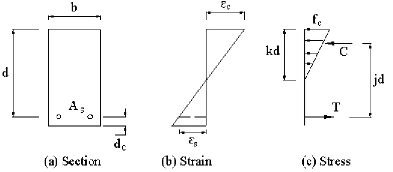
The compression stresses in a beam section shown in Figure 1vary linearly for zero at the neutral axis to a maximum stress of fc at the extreme compression fibre.
Figure 1.Strain and Stress distribution in straight line theory Based on Figure 1, the moment at service load is:
M
A f jd
or
M
f kjbd
s s
c
1
2
2
Where fs and fc are allowable steel and concrete stresses respectively. Comparing these equations and substituting for
j 1 k
3 , k (
n)
n
n2 2
n E
E S
C
and
Awhere Es and Ecare modulus of elasticity of steel and concrete respectively and
is steel ratio. Thenwe have:
) 3 1 ( k
d f A
M s s (1)
Strength Design (SD) Method
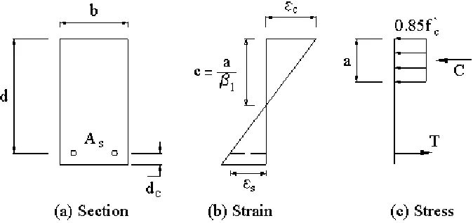
Based on the strength design method (using load factors and factored resistance), the linear elastic theory for stress is no longer valid. Instead an equivalent of rectangular stress block is used as shown in Figure 2.
Figure 2. Strain and stress distribution – equivalent rectangular stress block The ultimate moment is given by:
) 2 (d a f
A
Mu s y where
b
f
f
A
a
c y s
`
85
.
0
Where
f
yandf
`
care steel yield strength and concrete compressive strength respectively.Also, a cβ1 where β1=0.85, and =0.9 which is the strength reduction factor in flexure. Substituting for a in Muwe have:
)
`
85
.
0
2
(
)
2
(
b
f
f
A
d
f
A
a
d
f
A
M
c y s y
s y
s
u
Or simply:
)
`
59
.
0
1
(
c y y
S u
f
f
d
f
A
M
(2)Substituting for
M
and Mu from equations 1 and 2, we have:) 3 1 (
) ` 59 . 0 1 ( M
Mu
k f
f f f
s
c y y
M
M
f
f
u y
s
(3)where
) 3 1 (
) ` 59 . 0 1 (
k f f
c y
The moment ratio shown above represents the SDF. This ratio is a function of the steel yield strength, which is the most important parameter in SDM and the allowable steel stress, the most important parameter in WS. Also the parameter
is a function of the steel ratio, modular ratio, steel yield strength and concrete compressive strength. The effect of this parameter on SDF will be investigated.For determining the range of variability of
, a wide range of values for is considered. By changing the values off
y,f
`
c the values of k and
can be computed. The value of is increased up to
max, in which:b
max
0
.
75
wherey y
c b
f
f
f
87000
87000
`
85
.
0
1
Where
b is referred to as reinforcement ratio for a balanced cross-section (f
y andf
`
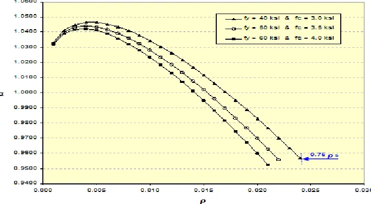
c are in psi). Figure 3 shows the variation of α with ρ. It is interesting to note that the value of
in most cases is very close to unity in the practical range of interest.Figure 3. Variation of α material properties in tension controlled, singly reinforced section
Doubly Reinforced Concrete Sections
Reinforced concrete sections are sometimes provided with compression reinforcement. With these assumptions, the force-equilibriums will be developed in order to arrive at an equation for SDF.
e
n
r n r
'(
)
2
In which:`
= Compressive steel ratio, and
e Balanced stress design, the steel ratio in which steel and concrete reaches the allowable stress.
In strength design:
max
0 75
.
'b
To ensure the yielding of compressive steel we must have:
` 1
87000
87000
`
`
85
.
0
y y
c Lim
f
d
d
f
f
Also the maximum strain for concrete is assumed to be 0.003.
Working Stress (WS) Design
The compression stresses in a beam section is shown in Figure 4.
Figure 4. Strain and Stress distribution in straight line theory
With the assumptions made for singly reinforced section, the moment at service load is:
s
s b d d f
f bjd
M (
`) 2
` ( `) By rearranging the above equation we have:`)) 1
`( ) 3 1 `)( ((
2
d d k
f bd
M s
(4)Where fs is the steel stress, which can be assumed as the allowable steel stress.
For locating the neutral axis or value of k, the transformed section needs to be considered. By referring to Figure 4 and setting the moment equilibrium about the neutral axis, we have:
j 1 k
3 where
k
n
d
d
n
n
((
') )
(
')
(
)
''
2
22
2
where
c s
E E
n ; Modular ratio
Strength Design (SD) Method
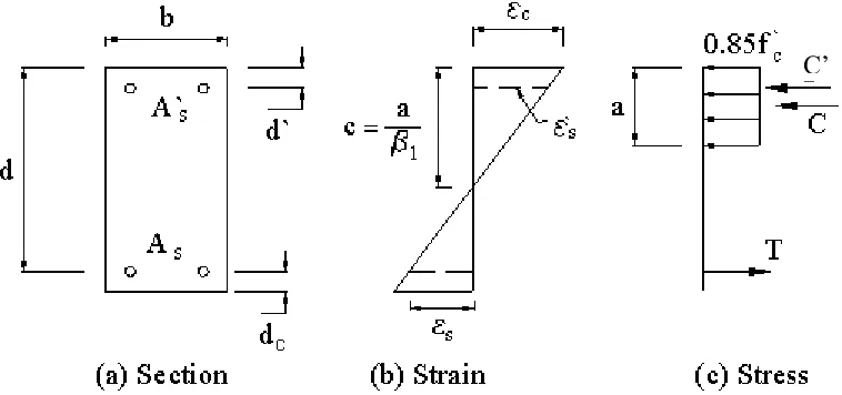
Based on the strength design method, the equivalent rectangular stress block for a doubly reinforced section is shown in Figure 5.
Figure 5. Strain and stress distribution – Equivalent rectangular stress block The ultimate moment is given by:
`)) (
` ) 2 ( ) `
((A A f d a A f d d
Mu s s y s y
Where
b
f
f
A
A
a
c y s s
`
85
.
0
)
`
(
Where
f
yandf
`
c are steel yield strength and concrete compressive strength respectively. Also, a cβ1 where β1=0.85, and =0.9 strength reduction factor in flexureSubstituting for a in Muwe have:
))
`
1
`(
`
`)
(
59
.
0
1
`)(
((
2
d
d
f
f
f
bd
M
c y y
u
(5)
SD Versus WS
Substituting for Mu and
M
in equations 4 and 5 we have:))
`
1
`(
)
3
1
`)(
((
))
`
1
`(
`
`)
(
59
.
0
1
`)(
((
2 2d
d
k
f
bd
d
d
f
f
f
bd
M
M
s c y y u
or
s y uf
f
M
M
(6)In which:
)
`
1
`(
)
3
1
`)(
(
)
`
1
`(
)
`
`)
(
59
.
0
1
`)(
(
d
d
k
d
d
f
f
c y
(7)Similar to the case of singly reinforced concrete section, the moment ratio shown above
represents SDF. This ratio is a function of the steel yield strength, and the allowable steel stress. Also the parameter
is a function of the steel ratios, modular ratio, steel yield strength and concrete compressive strength.For determining the range of variability of
, a wide range of values are considered. By varying the values off
y,f
`
c the values of k and
can be determined. The values of are changedsuch that all constraints in the design procedure as mentioned previously are satisfied. Again, the value of
in all cases was found to be equal to or close to 1.0.
For determining the serviceability design factor for a certain load condition, we can write:
M
M
S
ud
(8)In which:
Sd : Serviceability design factor
Mu: Design moment based on strength design method
M
: Design service (un-factored) momentload Unfactored load Factored w wu
(9)
sy d
f
f
S
(10)For design purposes, the above equation can simply apply to each load condition and related load factor. Also based on the results obtained for
, it can be assumed that this value is equal to unity: Finally, the recommended and simplified design equation for SDF is:s y d
f
f
S
(11)SERVICEABILTY DESIGN FACTOR FOR SHEAR
In this study, the requirements by ACI 318-95 (1995) for design shear strength are first defined based on the SD. The WS design procedures for shear are also defined. Based on design procedures using both SD and WS design, it is concluded that the major factors affecting the SDF are steel yield strength, strength reduction factor, , load factor, and the steel allowable working strength. The SDF derived here is applicable to reinforced concrete shear resistance in excess of that carried by concrete alone.
Based on ACI 318-95 (1995), in Working Stress (WS) Design:
A
s
V
V
f d
V
1.1 f b d
.
(12) Based on ACI 318-95, in Strength Design (SD) method:
A
s
V
f d
V
ФV
ФV
Ф
Ф
(13)
s
.
Ф
.
Ф
(14)
Equation 14 can be simplified to that shown in equation 10. The SDF depends on material properties, (fy,fs,f`c), shear force in member, (V, Vu) and the dimensions of member, (bw,d).
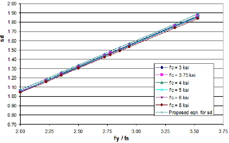
A sensitivity study was conducted to determine the effect of the above parameters on SDF. This was done with the aid of several design examples. Results of the study showed that for all cases, a value of unity can be assigned to α. Figure 6 shows variation of the Sd factor for different material parameters. This figure shows that the assigned value of α to unity is appropriate in the proposed equation 10. This indicates that the SDF depends on fy, fs and load factor ( ). Therefore, the equation for the SDF is the same as equation 11.
Figure 6.Serviceabilit design factor for diffetent material properties
SERVICEABILTY DESIGN FACTOR FOR DIRECT TENSION
To derive an equation for SDF for members subjected to direct tension, a similar procedure as that used for flexure and shear is used. The equations for WS and SD methods are used.
The SDF is expressed as:
(15)
s y
s y
U
y U s
SDM S
WSD S d
f
f
f
f
T
T
f.
T
f
T
)
A
(
)
A
(
s
where ere
where T and Tu are the unfactored and factored applied tensile loads respectively.
Therefore, the equation 16 for SDF is similar to that shown in equation 10. Therefore, the derived equations for SDF can be expressed in a simplified general form to include all possible cases including flexure, shear and tension as follows.
(16) where α is equal to 1.0
CONCLUSION
Current nuclear and building codes use different approaches for concrete design. The widely different approaches do not allow comparisons of these codes. This limit the usefulness of these codes since it is not clear how to apply them to different practices in different countries where national codes are required to be used. For nuclear containment structures designed in Canada, safety is at the heart of the design approach without undue conservatisms. In this paper a general methodology is presented to calibrate and compare different codes which are using different methodologies. This provides a key (or a Rosetta stone) by which one can compare the level of protection achieved by different codes without resorting to lengthy and expensive detailed designs. A simple equation is derived to find the relation between the strength design and working stress design methods. This equation can be applied to members subjected to flexure, shear, and tension.
ACKNOWLEDGEMENTS
The data analysis and numerical examples carried out by Mr. M. Atashi, P.Eng. is gratefully acknowledged.
REFERENCES:
ACI Committee 318-95, (1995), “Building Code Requirements for Reinforced Concrete 318, ACI 318 – 02, and Commentary ACI 318R – 02, ’’American Concrete Institute, Farmington Hills, Michigan.
ACI Committee 349-06, (2006), “Code Requirements for Nuclear Safety-Related Concrete Structures “, American Concrete Institute, Farmington Hills, Michigan.
ACI/ASME Technical Committee on Concrete Pressure Components for Nuclear Service, 2007, “Code for Concrete Containments (ACI 359-07),” 2007 ASME Boiler and Vessel Pressure 9 Code, Section III, Division 2, ASME, New York, 2007. 10.
CSA-A23.3-04 (2004), “Design of concrete structures”, CAN/CSA A23.3, Canadian Standards Association (CSA), Rexdale, Ont.
CSA-N287.3-14 (2014), “Design requirements for concrete containment structures for nuclear power plants”, Draft, CAN/CSA N287.3, Canadian Standards Association (CSA), Rexdale, Ont.
T
T
U
S d f s_SDM f s_WSD