Dynamic Analysis of Nonproportional Damping Structural Systems
Time and Frequency Domain Methods
F. Venancio-Filho ~>, Y.K.Wang 2>, F.B.Lin 3> , A.M. Claret 4> and W.G.Ferreira 5> 1) Catholic University of Rio de Janeiro-PUC-Rio, Rio de Janeiro, RJ, Brazil. 2) Brookhaven National Laboratory, Upton, NY.
3) Polytechnic University, New York, NY
4) Federal University of Ouro Preto, Ouro Preto, MG, Brazil 5) Federal University of Espirito Santo, Vitdria, ES, Brazil ABSTRACT
Structural systems composed of structural elements with different characteristics as NPP and soil and fluid-structure interaction systems present considerable nonproportional damping. The assumption of uncoupled modal equations with assumed modal damping ratios can lead to substantial errors in the dynamic analysis results of those systems. Therefore that assumption is not anymore accepted by the nuclear industry. Appropriate and more rigorous methods for the dynamic analysis of structural systems with nonproportional damping should be developed. In this paper pseudo-force mode superposition methods are developed which consider the nonproportional damping effect through a pseudo-force term in the RHS of the modal equations. These equations are then iteratively solved. The methods presented are considered in time and frequency-domain. The frequency-domain version is very suitable for the analysis of systems with hysteretic damping and frequency-dependent properties. Examples of time and frequency-domain analysis are presented.
INTRODUCTION
Structural systems composed of several structural elements with different properties can present high nonproportional damping. Typical systems of this category are interaction systems (soil, equipment, fluid-structure interaction) which are characteristic of NPP complex structures.
The Classical Mode Superposition (CMS) method assumes that the modal coordinates dynamic equilibrium equations are uncoupled and damping is considered through assumed modal damping ratios. This constitutes the damping proportionality hypothesis. The dynamic analysis of complex structural systems based on this assumption can lead to serious errors. The nuclear industry doesn't accept any more this type of analysis.
Nevertheless the method presents two main advantages over other time-domain methods: a good interpretation of the system behaviour through the analysis of natural frequencies and normal modes and economy of computational effort due to the possibility of mode truncation. According to Roesset et al [ 1 ] the interpretation of the system physical behaviour through the method is a strong motivation for its use by structural engineers. In complex systems, the analysis of natural frequencies and normal modes permits the evaluation of the influence of one part of the system upon the other (for example, the influence of less flexible or rigid foundations upon the structure). In this way, the model used in the analysis can be fairly assessed.
In order to explore the advantages of the method and, at the same time, consider in an appropriate way the damping nonproportionality improvements were added to that method. These improvements can be of two classes: 1. Approximate methods in which composite modal damping ratios are introduced according to certain criteria. Johnson and McCaffery [2] considered an equivalent modal composite damping ratio as a weighted sum of the different component damping ratios using the mass as weighting function. Stiffness can also be used instead of mass. Roesset et al [1] proposed an energy-weighted composite modal damping. This method is a combination of the two previous ones. In the present class the modal equations retain the uncoupling and are independently solved; 2. Exact methods. Here the term exact method refers to a method which doesn't make any approximation in relation to damping thus leading to a response closest to the true system response. Modal equations are now coupled and can't be independently integrated. All the exact methods are based on the time history integration process. They can be grouped into three categories: 2.1 Direct integration method - solution performed on the physical degrees of fi~eedom of the system; 2.2 Complex mode method - solution performed on the modal equations of the system; 2.3 Pseudo-force method - solution performed through integration on the system modal equations.
Pseudo-force methods have been recently thoroughly studied and have shown very good capabilities to tackle the analysis of nonproportionally damped systems. Several versions of these methods are presented by Udwadia and Esfandiari [3], Udwadia and Kumar [4], Tong et al [5], and Ibrahimbegovic and Wilson [6].
In this work the pseudo-force method developed by Claret and Venancio-Filho [7] and, recently, improved by Wang [8] and Lin and Wang [9] is presented. The former authors introduced a coupling index which measures the degree of nonproportionality and a convergence index which indicates the convergence of the iterative solution. Wang improved the
-)!:
SMiRT 16, Washington DC, August 2001 Paper # 1971
former version of the method by an ingenuous transformation on the diagonal terms of the generalized damping matrix thus drastically improving the convergence of the iterative process.
More recently frequency-domain methods have been employed for the analysis of systems with nonproportional, hysteretic and frequency-dependent damping by Mansur et al [ 10]. These methods can be formulated in modal coordinates and in nodal coordinates, Venancio-Filho [11]. The nodal coordinate formulation is more appealing as it avoids a flee- vibration analysis and automatically includes the static response.
Examples of time and frequency-domain analysis are presented. TIME D O M A I N P S E U D O - F O R C E M E T H O D
Consider a discretized structural system with N dynamic Degrees of Freedom (DOF's). The dynamic equilibrium equation of this system is
m ~ + c i , + k v = p ( t )
(1)
where m, c and k are, respectively, the (NxN) mass, damping and stiffness matrices; v, i, and i~ are, respectively, (Nxl) vectors of nodal displacements, velocities and accelerations, and p(t) is the (Nxl) vector of nodal time-varying applied forces. The nodal displacements v can be expressed in terms of modal or generalized coordinates V by means of the modal transformation
v = ~ V (2)
where • is the matrix whose columns are the system normal modes. Taking into account Eq. 2 and the orthogonality property of the normal modes leads to the modal or generalized coordinate equation
I V + C g + A V = P ( t ) .
(3)
In this equation V, V and i~ are, respectively, the vectors of modal displacements, velocities and accelerations and P(t) = ~t p is the vector of modal forces; I is the (NxN) unit matrix, C = ~t c • is the generalized damping matrix, and A is the diagonal matrix composed by the system natural frequencies squared.
If damping is proportional, C is diagonal and, consequently, the individual equations of Eq. 3 are uncoupled. In this case they are independently solved. When damping is nonproportional, C is nondiagonal, the individual equations from Eq. 3 are coupled and can't be independently solved. The pseudo-force method introduced by Claret and Venancio-Filho [7] is an e x a c t iterative method based on the pseudo-force concept to solve the coupled system, Eq. 3.
The generalized (nondiagonal) damping matrix C can be split as
C = C d n t- C f (4)
where Cd is a diagonal matrix composed by the diagonal elements of C and
Cf
has zero diagonal elements and the corresponding off-diagonal elements of C. Substituting for C in Eq. 3 from Eq. 4 leads toIN-t-C d V + A V - P - C f ~r.
(5)
The LHS of Eq. 5 is uncoupled and the damping nonproportionality is taken into account through the pseudo-force vector - C f V in the RHS. The n th generic equation from eq. 5 is solved by an iterative process whose k th step is given by
N
.. (k-l) Vn ( k ) + C n n *n ( k ) + A n V ( k ) = P n - ~ Cnm v m •
m=l m~n
(6)
The generalized load is approximated by piece-wise linear steps. In each step the solution is performed by Duhamel integral (Claret and Venancio-Filho, [7]) or by the piecewise exact method (Ibrahimbegovic and Wilson, [6]).
Two indexes were introduced by Claret and Venancio-Filho. The coupling index is defined as
c~ = max
i 2 1
Cmn CmmCnn(7)
and indicates the degree of nonproportionality. A convergence index is defined for each mode. For the n th generic mode the convergence index is
I C -
rn=l
m ~ n
(-0 m
D,~m __-Z- Cnm
C0 n
-1
(8)
[6 ) ( 2 ) 1 - 1 / 2 Com C
In which Dmn = -13mn 2 + _ ~ n f 3 m n , 2 , [3ran = , ~n = nn and COrn and CO n are, respectively, the
o n 2co n
frequencies of modes m and n. The greater ICi the faster the convergence of the iterative process expressed by Eq. 6 will be. Wang [8] introduced a modification of matrix C splitting, Eq. 4, which drastically improves the convergence of the process. Now C is splitted as
L R (9)
C = C d + C d + Cf and Eq. 5 transforms into
L
I V + C d V + A V : P - ( C + C f ) ~ r (10)
L
Each term of C d is calculated by the following equation:
N
L L
Cnn = Cnn + Cnn m=l m~n
CO n
Cnm ~mn
1
Ii- mn/ +
o n co n(11)
L
Eq. 11 is nonlinear in Cnn and is iteratively solved.
F R E Q U E N C Y D O M A I N M E T H O D
The initial step to develop a frequency domain method is to consider Eq. 1 in terms of Fourier Transforms. Thus taking Fourier transforms of both sides of Eq. 1 yields
[ - ~ 2 m + i f2c + (k + ik H)I V (f2)= P(~)
(12)
dependent. Hence a frequency-domain method is mandatory for a rigorous analysis when hysteretic damping and frequency- dependent properties are present.
The inversion of Eq. 12 leads to
V ( ~ ) : H(~) P(f2) (13)
where
. ( a )
a 2
= - m + i f ~ e + + i k H
(14)
is the complex frequency response matrix. The Fourier transform of the response, Eq. 13, in then inverse transformed in order to obtain v (t), the response in the time domain.
Eq. 12 can be transformed to a modal or generalized coordinates equation through the modal transformation leading to
I - f22I + i(f2 C + K H ) + A] W(f2)= Q(f2)
(15)
In this equation C and KH are, respectively the generalized viscous and hysteretic damping matrices and W(£)) and Q(f2) are, respectively, the Fourier transforms of the modal or generalized coordinates and the generalized load. On the other hand I and A are diagonal matrices and the coupling stems only from damping. Eq. 15 can be solved by an extension of the iterative process proposed by Jangid and Datta [ 12] based in the pseudo-force concept as in the time domain.
EXAMPLES
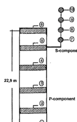
The first example is a representative model of a typical NPP building with base-supported equipment as illustrated in Fig. 1 (Wang [8])° The primary component (building) consists of weightless shear beam elements and lumped masses and is
! , ~ ' ~ ; , : ~ / / ~ : ...
~o~po.~.t
... ~ .
~
P~compOnent
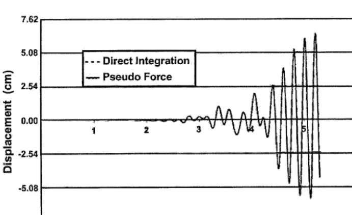
fixed in the ground. The model has 5 DOF's with each node free to translate in one horizontal direction. The secondary (S) component model consists of 4 translational DOF's in the horizontal direction. The base of the secondary component is coupled to a mid-elevation primary component node. The composite damping matrix is calculated according to Pajuhesh and Hadjian [13]. The input ground excitation is the E1 Centro (1940) earthquake. Fig. 2.a displays the response of DOF 6 in the primary system and Fig. 2b, the response of DOF 10 in the secondary system. The reponses obtained by the pseudo-force method and direct integration match perfectly. In order to show the drastic improvement of the convergence the response was calculated by the former method [7] and by the improved one [8]. The difference in CPU time is remarkable: 7.2 sec in the improved method and 71 sec in the former one.
,0=76
0.51 , , - - D i r e c t i n t e g r a t i o n
E o.2s
. . .
¢ 0.00 m
E
o = -0;2:5
-0.51
• : ~ . . .
.a
,0.7,6
.:t :,02
I
:....
~,ouoo ~oroo
h ~:,:A,:A
A: A
...~ ' ^ .... r c .... i .... ili-I!-~ !' ...
... ~, ... ~ ... ; v ' ...
i i'rV ~ rllfll~V '~
.... :
Ii ~
~ ...jr"
"
V ~v
, . r ,
T i m e (see)
Fig. 2a. Displacement history at node 6
A
E
0 2,54
7,~62 . . .
s.0s .1.i.: :...Direct..integraii.on ... : ... :~][....,
E o.oo
..(;3:
i~: , 2 ~ ...
~Q
-5,08
-7,62 ...
p ...
A i!E it!i i: !,
,
v , ~ : ... v i , ~ ...
v!r
:"t ... !,i ...
:Time (sec)
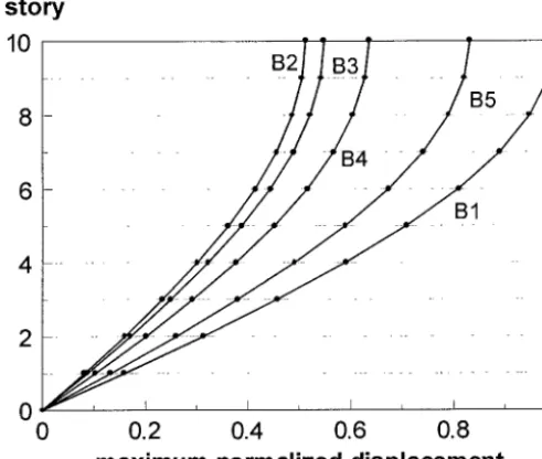
The second example is a 10 story shear-building where discrete dampers are introduced between the floors to control the dynamic response (Sahlit and Avila [ 14]), Fig. 3. Five cases of arrangements of the dampers are considered. Case B l: no dampers; Case B2: dampers in all stories; Case B3: dampers in the first five stories; Case B4: dampers in stories 1, 3, 5, 7 and 9; Case B5: one damper only in the first story. Fig 3 displays the damper arrangement of Case B4. The shear- building properties are story stiffness k = 64,628.37 N/m and floor mass: m = 1.0 kg (0.5 for upper floor). Rayleigh damping
/ / / / / / / / 1 / / / / / / / / f
/ / / / / / / / . ,
F - - - ~ --j ,
/ / / / / / / / # / / / / / / / J /
V--~---J
/ / / / / / / / t ' / / / / / / / / # / / / / / / / / t ' / / / / / / / / /
F-~--J
Fig. 3 - Shear-building with discrete dampes
story
0 A A a
8
. . . B4 . . .
6
4 --
2 - -
0 I I i I i I
0 0.2 0.4 0.6 0.8 1
maximum normalized displacement
Fig. 4a. Normalizaed Floor displacements (c=100Nsec/m)
story
1 0 B 2 " B " " "
. . . B5 . . . .
. . . .
6
4
2
0
0 0.2 0.4 0.6 0.8 1
maximum normalized displacement
Fig. 4.b - Normalized Floor Displacements (c=2000Nsec/m)
is considered for the structure. The coefficients a0 and al of the Rayleigh damping matrix c = a0m + alk are obtained with the assumption of a modal damping ratio of 5% in the first and second modes. The discrete dampers are considered with c = 100 Nsec/m and c = 200 Nsec/m. The shear building is submitted to the NS component of the 1940 E1 Centro earthquake. The overall damping is nonproportional due to the presence of the discrete dampers and the dynamic analysis is performed by the time-domain pseudo-force method. The normalized floor displacements relative to Case 1 displacements are displayed in Figs. 4a and b.
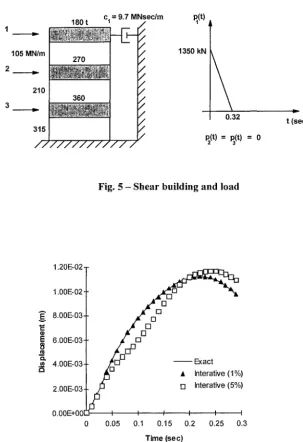
The final example is a frequency-domain analysis. The shear building of Fig. 5 with the indicated properties is subjected to the impulsive loading displayed in the figure (Ferreira [ 14]). The frequency-domain analysis is performed in both nodal and modal coordinates using iterative process. Here the nodal coordinate analysis is considered the exact solution. The response of the upper floor is given in Fig. 6. The analysis in modal coordinates with a 1% tolerance in the iterative process shows a perfect agreement with the exact analysis.
105 MN/m
210
315
/ /
180 t cl = 9.7 MNsec/m pl(t)
/ /
¢
/ / / / / / / / / / /270
360
~i . . . ', " !iS I
q J , 4 r J J J ~ , W ~
1350 kN
t
2
P2(t) = P3(t) = 0
t (sec)
Fig. 5 - Shear building and load
1.20E-02 1"00E-02 t
o.oo -o l
,oo _o T
~" 4.00E-03' )=~]D ~ Exact i~ / )~O A Interati.ve (1%)
2 00E 031
0.00E+0C
0 0.05 0.1 0.15 0.2 0.25 0.3 Time (se c)
CONCLUSION
Time and frequency-domain pseudo-force methods for dynamic analysis of structural systems with nonproportional damping were presented. These methods permits appropriate and rigorous analysis of that system as indicated in the presented examples. Frequency-domain methods are mandatory for systems with nonproportional, hysteretic and frequency- dependent properties.
ACKNOWLEDGMENT
The first author acknowledges the support for this work from the State of Rio de Janeiro Foundation for Research Support- FAPERJ through the Grant E-26/150.994/2000.
R E F E R E N C E S
1. Roesset, J°M. et al, "Modal Analysis with Foundation Interaction", Journal of the Structured Division ASCE, March 1973.
2. Johnson, T.E. and McCaffery, R.J., "Current techniques for analysing structures for seismic effects", ASCE National Meeting on Water Resource, New Orleans, 1969.
3. Udwadia, F.E. and Esfandiari, R.S., "Non-classically damped dynamic systems", Journal of Applied Mechanics, Vol. 57, 1990, pp. 423-433.
4. Udwadia, F.E. and Kumar, R., "Iterative methods for Non-classically damped dynamic systems", Earthquake Engineering and Structural Dynamics, Vol. 23, 1994, pp. 137-152.
5. Tong, M., Liang, Z. and Lee, G.C. "Physical space solutions of nonproportionally damped systems", National Center for Earthquake Engineering Research, TR NCEER 91-0002. 1991.
6. Ibrahimbegovic, A. and Wilson, E.L., "Simple numerical algorithms for the mode superposition analysis of linear structural systems with nonproportional damping", Computers and Structures, Vol. 43, 1989, pp. 523-531.
7. Claret, A.M. and Venancio-Filho, F., "A modal superposition pseudo-force method for dynamic analysis of structural systems with nonproportional damping", Earthquake Engineering and Structural Dynamics, Vol. 20, 1991, pp. 303-315.
8. Wang, Y.K., "Seismic analysis of coupled structural systems with nonproportional damping", Ph.D. Dissertation, Polytechnic University, New York, 1999.
9. Lin, F.B. and Wang, Y.K. "A new pseudo-force iterative method for dynamic analysis of structural systems with non- proportional damping", submitted to Earthquake Engineering and Structural Dynamics, 2000.
10. Mansur, W.J., Ferreira, W.G., Claret de Gouveia, A.M., Venancio-Filho, F. and Carrer J.A.M., "Time-Segmented frequency-domain analysis for non-linear multi-degree of freedom structural systems", Journal of Sound and Vibration, Vol. 273, 2000, pp. 457-475..
11. Venancio-Filho, F., "Methods for nonlinear structural analysis in the frequency domain", Nonlinear Dynamics, Chaos, Control and Their Application to Engineering Sciences, Vol. 5: Chaos, Control and Times Series, J.M. Balthazar, P.B. Gongalves, R.M.F.L.R.F.Brasil, I.L. Caldas, F.V. Rizatto, Editors, Rio Claro SP, Brasil, 2001, pp. 368-376.
12. Jangid R.S. and Datta, T.K., "Spectral analysis of systems with non-classical damping using classical mode superposition technique", Earthquake Engineering and Structural Dynamics, Vol. 22, 1993, pp. 723-735.
13. Pajuhesh, J. and Hadjian, A.H., "Dynamic Interaction of Components, Structure and Foundation of Nuclear power facilities", Proc. of the Fifth SMiRT Conference, Vol. K(a), K3/9, 1977.
14. Sahlit, C.L. and Avila, S.M. "Structural dynamic response control through the use of discrete dampers" (in portuguese), Journal of Engineering, Science and Technology, Federal University of Espirito Santo Technological Center, Vit6ria, ES, Brazil, Vol. 11, 1999, pp. 3-9.