Vol.8 (2018) No. 6
ISSN: 2088-5334
Behavior of Modified Long Links with Supplemental Double
Stiffeners on Eccentrically Braced Frames
Musbar
#, Bambang Budiono
#, Dyah Kusumastuti
#, Herlien D. Setio
# #Department of Civil Engineering, Institut Teknologi Bandung, Jl. Ganesa 10, Bandung, 40132, Indonesia E-mail: [email protected], [email protected]
Abstract— Initial failure of long links caused by fracturing and buckling occurs on the flange and web at the end of the link. Local damages are caused by the influence of the dominant bending moments compared to shear forces. The advantage of using long links includes allowing for larger openings in rooms, which makes it popular among architects. Efforts to prevent these specific failures are not covered in the rules, and there are few types of research that examine improving the performance of long links. The focus of this study is to provide information on using supplemental double stiffeners at the ends of the link without changing the long link behavior. The behavior of long links is maintained by keeping the flange failures on the flange at the end of the link. The supplemental double stiffeners improve the performance of the long link by extending the inelastic zone and slowing the failure rate of the flange. This experimental study was carried out on four models of the long link consisting of a standard model and a model modified by the addition of supplemental double stiffeners at the flange. Long link models were modified with variable thickness and holes width on the supplemental double stiffeners. The results showed that the addition of the supplemental double stiffeners improved the performance of long links compared to the standard link that is by the requirements of AISC 341-10. The supplemental double stiffeners are an alternative to improved long link performance, making it more effective in the application of its use in steel construction.
Keywords— supplemental double stiffeners; thickness; hole width; performance.
I. INTRODUCTION
Eccentrically braced frame system (EBFs) has excellent elastic stiffness under lateral loading and has good ductility when under large earthquake loads [1]. EBFs is an excellent compromise between the moment resisting frame (MRF) and concentrically braced frames (CBF) system so that it is suitable and beneficial to apply structures to make them resistant for earthquake loads [2]. EBF system can be planned in the state of a moderate earthquake load to minimize structural and nonstructural damage. In the event of a severe earthquake, EBF structure must be designed to be able to maintain the inelasticity of the link which in extreme cases can significantly cause permanent deformation. The ability of EBFs to accommodate large room openings make this very popular among building designers.
Based on EBFs method, yielding occurs on a link element due to either shear or moment. Yielding is highly dependent on the length of the link [3], [4]. For long links, shear experiences yield when the moment reaches the end of the plastic moment (Mp). The collapse of a long link is due to bending deformations caused by the lateral torsional buckling and buckling in the flange and web. Enormous strain on both ends of the link can cause a fracture at the end
of the weld joint. The sheer force acting on the link has a constant value throughout the link, whereas the moment is not. Also, the moment is concentrated at both ends of the link, and the value decreases towards the center.
Engelhardt and Popov [3] stated that the use of long links on the EBFs structure is not recommended because of its low performance. Subsequently, many experimental and analytical work [1], [5]-[10] discussed the effect of link length on the performance of the EBFs. All of them showed that the performance of long links is less than those of short ones. Therefore, they recommend that links exceeding
e > 1.6 M V⁄ in length not to be used as a link to the column on EBFs.
inelastic rotation ranging from 0.04 to 0.09 rad. However, the weakness in the long link is caused by the formation of a plastic hinge on the flange in the welding zone at the end of the link with is then accompanied by failure caused by lateral torsional buckling, and fracture and buckling of the flange [4], [5], [9], [12], [14], [16], [17], [18], [19]. Some researchers suggested that avoid this weakness through limiting the slenderness of the flange. Richards [9] and Okazaki [15] limited the slenderness to between
0.30 E E⁄ and 0.38 E E⁄ . It was found that the
intermediate links are most susceptible to local buckling, so it does not comply with the prediction of the rotation design. This condition is caused by the influence of the spacing between web stiffeners and limiting the slenderness of the flange to b 2t⁄ .
Subsequent research was conducted to improve the performance of the link through numerical and experimental study. Prinz and Richards [8] reduced web section of the link that is connected to the column and found that the value of strain and stress on the flange is reduced, but the strain and the triaxial stress increase on the web at the edges of the hole. To cope with this phenomenon, Naghipour [20] suggested reducing the cross-section of the web that can rotate about the same or smaller than the cross-section of the link without a reduced web. Beam-column link model with reducing beam section (RBS) found that the time is yielding, and ductility is higher than the model without RBS. Berman [11] reported that the reduction in cross-section of the flange at the end of the link could reduce the strain significantly on all the links, especially plastic strain on the flange at the end of the link where the location of a potential fracture can occur.
Based on the results from the previous studies, failure of long links occurs at the end of the link. Some research has been done to avoid failure due to bending dominant force by adding stiffeners to the web and flange. Yurisman [14] conducted a study on short links that were added diagonal stiffeners on the web. Danesh [20] reported utilizing diagonal stiffeners on the web and supplemental stiffeners on the flange. Furthermore, Okazaki [13] and Hong [21] reported using supplemental double stiffeners in connecting a beam to the column and found excellent performances on the link. Stephens and Dusicka [22] reported that the use of continuous stiffeners on the short link could improve its performance, exceeding the standard shear link performance according to the requirements of AISC 341-10. Furthermore, Yurisman [14] and Danesh [16] reported that retrofitting the link delayed failure at the end of the link. Reinforcement at the ends of long links prevents the early failure that is preceded by the formation of the plastic hinge on the flange.
II. MATERIAL AND METHOD
The numerical analysis of long link modified with supplemental double stiffeners was conducted by ANSYS 16.0 software by the requirements specified by AISC 341-10. The results of the numerical analysis showed that the failure of long links occurs under three conditions. First, a failure occurs in a zone close to the ends of links without the extension of the plastification zone. Second, the failure occurs in the zone near the confluence with the extension
plastification. Third, failure shifts towards the middle of the link without plastification at both ends. The experimental study showed that the long link modifications maintained the failures by the requirements of AISC 341-10.
A. Improved Links Proposed in this Study
This study used supplemental double stiffeners that are connected between each edge of the link and the intermediate stiffeners. The supplemental double stiffeners are used to get the best performance from the long link. It does not intend to change the performance of the long link to be similar to that of a short link or an intermediate link. This can be done by controlling the capacity of the overall modulus section. Also, the best performance of the long link can be measured by using a preliminary numerical analysis where the length of the plastification zone, the model failure position, and the model failure mechanism are observed. These variables can be determined by changing the thickness and width of the holes of the supplemental double stiffeners. The main objective of using double stiffeners is to increase the capacity of the modules section in resisting flexural force as well as to increase the capacity of the long link to withstand shear forces. Because the effects of shear forces on the long links are not dominant, the modulus section is decreased by providing open slide holes on the outer sides of the double stiffeners, as shown in Figure 1. Limitations used in this study for the supplemental double stiffeners are as follows:
r = B ; 0,1H ≤ T ≤ 0,25H; 0,2 b ≤ B ≤ 0,4b (1)
where bf = beam flange width and H = beam depth.
The supplemental double stiffeners on the profile WF increases the capacity of moments and shear forces, thus preventing early failures due to buckling and fracture that occurs on the flange at the end of the links. The supplemental double stiffeners could be an alternative to increase the long links’ performance, thereby becoming more effective in their use in steel construction. The supplemental double stiffeners can additionally increase link capacity in restraining flexural force concentrated at the ends of the long links so the failure caused by buckling and fracture of the flange can be slowed.
Fig. 1 Supplemental double stiffeners limitations
B. Material
The steel profile used for the numerical and experimental study was WF 200.100.5,5.8, which met the requirements for slenderness and on the capacity of the power tools used in laboratory testing. Profile Wide flange (WF) was more commonly used in the structure of the EBF. The long link
1.5bf
H
a a
Th
Th r
model follows the specifications set by AIS 341-10. The vertical stiffeners were placed on both sides of the web. The width of the vertical stiffeners should be more than #$−
2&', and the thickness should be the greater value between
0.75 &' and 10 mm. The maximum spacing between vertical
stiffeners was 1.5 bf. Link length ratio (ρ) analyzed was 3.03 of 100 cm, complying with the requirements of AISC 341-10. Table I shows the of yield stress (Fy), ultimate stress (Fu) and elongation (%) of steel taken from each element of the link and stiffeners that was subjected to a tensile test.
TABLEI
RESULTSOFTENSILETEST
C. Model
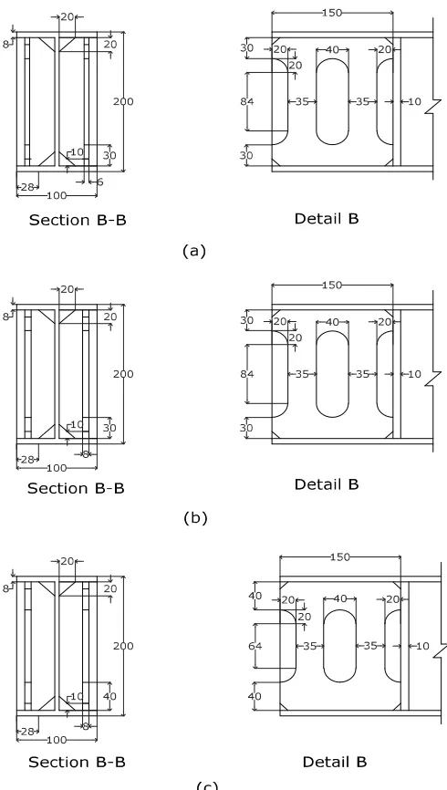
Selection of the experimental model was based on the results of the numerical analysis. The model was selected based on performance criteria which represented the best model to resist loading. The standard link and the link modified with the supplemental double stiffeners are shown in Figure 2. Thickness and hole width in the supplemental double stiffeners served as the main parameter to control and view the position and length of plastification failure. Configurations for the supplemental double stiffeners are shown in Figure 3. Both parameters could arrange this type of failure. Modulus of cross-section values of the models, which was based on the thickness and hole width, are shown in Table 2.
Fig. 2 Models (a) standard link, and (b) link with supplemental double stiffeners
A groove weld was placed at the end of the outer side of the flange and on the outer supplemental double stiffeners, with the angle of the flange cut by 45). The purpose of the weld was to avoid early failure due to fracture at the end of the link. However, a fillet weld was performed on the connection zone between the vertical web stiffeners and the inside of the flange, as well as on both sides of the web and at both ends of the link. Initial failure due to fracture is predominantly caused by concentrated moment force. It is predicted that there would be no early failures in the welding zone, so the connection will remain secure until the model fails. The type of weld connecting a standard link and a modified link with supplemental double stiffeners are shown in Figure 4.
Fig. 3 Configurations of the model with supplemental double stiffeners (a) MPVT02, (b) MPVT03, and (c) MPVL0
Web stiffeners
150
Double stiffeners
8 10
B
B B
e=1000 8 10
(a)
(b)
150
e=1000
150 150 A
A
bf
H
tw tf
SECTION A-A Th
bf
H
Th
tw ts
tf
SECTION B-B
Web stiffeners End plate
Model Fy (Mpa) Fu (Mpa) Elongation (%)
Web 501.99 595.61 16,05
TABLEII
MODULUSOFCROSS-SECTIONOFTHEMODEL
Model
Supplemental double stiffeners
Modulus of cross-section
Thickness (ts) (mm)
Hole width (th) (mm)
(Zp) (mm3)
Enhancement (%)
Standar - - 200152 0.00%
MPVT02 6 30 255592 27.70%
MPVT03 8 30 274072 36.93%
MPVL03 8 40 292312 46.05%
Fig. 4. Type of weld at the end of each model, a standard link and a modified link
D. Loading Pattern
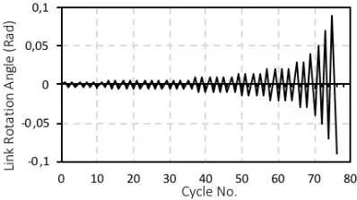
Loading patterns are arranged using AISC 341-10 as shown in Figure 5, which followed the loading pattern based on test results from Richards and Uang [10] as well as the proven performance based on the results of experimental studies comparing several types of loading patterns by Okazaki [17]. Although the AISC 341-10 guidelines contain the loading tests for a beam to column connection in a moment – frame system, this loading pattern can be applied to test the link to columns connection on an EBFs structure. Daneshmand [5] reviewed the effect of using different loading patterns: AISC 341-02, AISC 341-05, and ACT24 to a link with similar properties.
The results showed that the use of loading pattern AISC 341-05 demonstrated a rotational capacity more significant than the results of the other patterns. This fact confirms that loading patterns affect rotational capacity. Many recent studies were based on the AISC 341-10 rules regarding the use of EBF loading patterns.
Fig. 5 Cyclic loading protocol using AISC 341-10 guideline
E. Experimental Setup
Selecting the correct electoral boundary conditions and loading pattern would reflect the real conditions of the EBF structure. Richards and Uang [23] proposed a boundary conditions model of the link in which the load is applied by imposing transverse displacements on the right end nodes. Left end nodes were permitted to translate horizontally but were constrained so that all have the same horizontal translation. This loading method will produce a constant shear force along the link with the same end moments and without any axial force. This boundary conditions model was applied by later researchers, including Mohebkhah [12], Daneshmand [5] and Nikuokalam [24].
Fig. 6 Boundary conditions with restraints ∆+= 0 and without restraints the
axial force ∆+≠ 0
Dusicka [25], Corte [26] and Stephens [22], [27] applied the boundary conditions where the degree of freedom to translate and rotate in all axial direction on one side of the link is restrained. The other end of the link could translate in the load direction and the direction parallel to its length as shown in Figure 6. Corte [26] studied a combination of axial force parameters, the ratio of the flange to the web, and the ratio of the link length and the high-profile cross-section used.
The results of the experimental and theoretical studies indicated that there is a substantial value over different ranges due to the presence or absence of an axial force on the link. Corte [26] studied the occurrence of buckling on a model IPE 600. The model with the restraints on the axial force showed a hysteretic curve and a positively sloped trend caused by the onset of the dragging axial force which produced a supplemental influence and when adding transverse force. In the case of other models, hysteretic
12 10
12 10
8 8 10
10
E7018
E7018
E7018 E6013
E6013 8, MPVT 02 10, MPVT 03 10, MPVL 03
WF 200.100.5.5.8
WF 200.100.5.5.8
End plate 40x400x400
curves with and without restraints axial force showed stable behavior suggesting that different loads in both boundary conditions can be ignored. In this study, the boundary conditions adopted were similar to the work conducted by
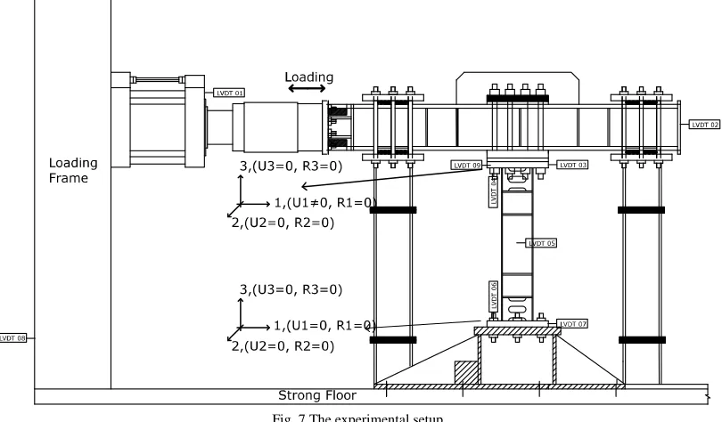
McDaniel [28], Yurisman [14], Dusicka [25] and Corte [26] through restraining the deformation due to an axial force. The experimental setup is shown in Figure 7.
Fig. 7 The experimental setup
III. RESULTS AND DISCUSSIONS
Based on the previous numerical analyses, the contribution of supplemental double stiffeners on MPVT02 and MPVT03 models does not add ductility compared to that of standard models but improves the moment strength of the link. These conditions had been predicted since the failure of the second link occurs at the end of the long link that was dominated by fractures in the flange. Extension of plastification in zone II was not very effective in increasing the ductility of the long link because the fracture in the flange occurred early. The contribution of supplemental double stiffeners in the MPVL03 model was better at increasing its ductility compared to other models. These conditions have been predicted from the beginning because fractures dominated link failure at the flange in the zone I and buckling at the web and flange in zone II. Extension of plastification in zone II was very effective in increasing ductility of the long link by slowing the rate of fracture at the flange. Zoning of the plastification zone observed on the test objects is shown in Figure 8.
The effect of the supplemental double stiffeners on the edge of the link in models MPVT02 and MPVT03 caused it more difficult to deform than the standard models, thus requiring a higher lateral force. Supplemental double stiffeners on MPVT02 and MPVT03 also affected web yielding at the end of the link. Yielding at the flange on a standard, MPVT02, MPVT03, and MPVL03 models occurred at the same load step while yielding on the web happened due to loading at a different step. Figure 9 shows the behavior and performance of the models. Strength, stiffness, ductility, as well as energy dissipation, can be derived from the hysteretic curve. Failure patterns of the standard, MPVT02, MPVT03, and MPVL03 models are different from each other. When the rotation showed 0.0075
rad at the flange of the standard, MPVT02, MPVT03, and MPVL03 the models experienced yielding in zone I. Initial local buckling began to form on the standard models at a rotation of 0.03 rad. The propagation of cracks occurred on the flange at the end of the link outside the welding area between the flange and the pedestal plate at a rotation of 0.04 rad.
Fig. 8 Zoning observed on (a) link standard, and (b) link with supplemental double stiffeners
The supplemental double stiffeners in the MPVT03 model could improve the strength greater than the standard and MPVT02 models. Crack initiation started on one side of the flange on the bottom in the zone I, outside the welding area at a rotation of 0.03 rad. Figure 11 shows a fracture and local buckling on the flange at zone II of the MPVT03 model. In this model, plastification was lengthened, but this condition could not improve ductility. Failure occurs in the same load steps for the standard link, MPVT02 and MPVT03 models due to fracture on the flange at the ends of the link which made supplemental double stiffener on these models less than optimal.
Fig. 9 Fracture and local buckling on the Standard Model
Fig. 10 Fracture on the MPVT02 model
Fig. 11 Fracture and local buckling on the MPVT03 Model
Different conditions occurred in the MPVL03 model, which could effectively solve the problems that were observed on the MPVT02 and MPVT03 models. The
addition of the maximum length plastification in zone II, slowed the fracture in zone I. Plastification in zone II was characterized by the buckling in the flange and web as shown in Figure 12. The MPVL03 model performed better compared to other models, which could be seen by its greater strength and ductility. Table III shows the occurrence of yielding on the web and flange of the models tested — the yielding on the flange in the zone I for all models showed deformation and rotation when loading with a displacement of 7.5 mm and rotation of 0.0075 rad. Yielding occurs at the flange in zone II for all the models with the supplemental double stiffeners.
Fig. 12 Fracture and local buckling on the MPVL03 Model
Different, yielding conditions on the web in zones I and II showed that the supplemental double stiffeners had some effect on the plastification of the models. Longer yielding occurs in the web of the models with supplemental double stiffeners compared to that of the standard models in the zone I which shows that the contribution of the double stiffeners in resisting shear force worked well. The yielding on the web of the MPVT02 models in the zone I was faster than that of zone II while the MPVT03 and MPVL03 models experienced yielding on the web in zone II faster than zone I. These conditions explained that the variation in thickness and hole width of the supplemental double stiffeners showed different behavior towards yielding at the web. These modifications provided the added value in improving the capacity of the long link to resist bending forces, thus link failure took longer due to the reduced influence of the dominant bending force.
A. Overstrength
Table 4 shows the overstrength values of the standard, MPVT02, MPVT03 and MPVL03 models which were calculated as the ratio of -.⁄-/, where -. is the ultimate shear force and - /is the nominal shear force. Under the terms of AISC 341-10 seismic provisions [29], the value of
- /is calculated based on the lowest value between
- 0and 2M e⁄ . Based on the calculations for steel profile
effected by variations in the thickness and hole width on the supplemental double stiffeners. The plate thickness and the
hole width influence the value of the plastic moment, which then influences the smallest the value of - /.
TABLEIII
CONDITIONFORYIELDINGTHATOCCURSINALLTHEMODELS
Plate Zone by (mm) Rotation (rad)
Standard MPVT02 MPVT03 MPVL03 Standard MPVT02 MPVT03 MPVL03
Flange I 7.5 7.5 7.5 7.5 0.0075 0.0075 0.0075 0.0075
II - 15 15 15 - 0.015 0.015 0.015
Web I 10 20 20 20 0.01 0.01 0.02 0.02
II - 30 15 15 - 0.03 0.015 0.015
TABLE IV
COMPARISON OF OVERSTRENGTH AND ROTATION OF THE MODELS TESTED
No Model Vn (kN)
Vu (kN)
Overstrength (Ω)
Rotation
Measured Target by AISC 341-10 γy (rad) γu (rad) γp (rad) γp (rad)
1 Standard 160.70 220.65 1.37 0.0075 0.05 0.0425 0.02 2 MPVT02 205.22 237.56 1.16 0.0075 0.05 0.0425 0.02 3 MPVT03 220.05 251.30 1.14 0.0075 0.05 0.0425 0.02 4 MPVL03 234.70 286.20 1.22 0.0075 0.07 0.0625 0.02
Fig. 13 A comparison of backbone curve of the models
The Over strength value of the standard models was higher than the other models as shown in Table IV. The difference in values was due to the nominal shear forces of the standard model being smaller than the other test objects. Supplemental double stiffeners on the MPVT02, MPVT03 and MPVL03 models gave the effect of adding to the cross-sectional area so that the nominal value of the shear force becomes more significant than the standard models. The standard links, MPVT02, and MPVT03 models reached yielding and a similar failure at a rotation of 0.0075 rad and 0.05 rad, while failure that occurred in the MPVL03 model needs a maximum rotation of 0.07 rad. Based on the requirements of AISC 341-10, the plastic rotational is expressed as the difference in value of the maximum rotation and the elastic rotation. Plastic rotation of the standard, MPVT02 and MPVT03 models is 0.0425 rad and for the MPVL03 model the value is 0.0625 rad which passes the value required, which is 0.02 rad. The strength of the MPVT02, MPVT03 and MPVL03 models increased by 7.67%, 13.89% and 29.71%, respectively compared to the standard model, as shown in the Figure 13.
B. Ductility
Ductility is defined as the ratio of the maximum displacement and the displacement at the beginning of yielding. Initial yielding of the standard, MPVT02, MPVT03 and MPVL03 models occurred at a rotation of 0.0075 rad and a displacement of 7.5 mm. The failure of the standard, MPVT02, and MPVT03 models occurred at a rotation of 0.05 rad and a displacement of 50 mm while for the MPVL03 model, failure occurred at a rotation of 0.07 rad and a displacement of 70 mm. Table V shows the ductility of the models. The highest value for ductility being 9.333 which is for the MPVL03 model, while the others have a value of 6.667.
TABLE V
COMPARISONSOFDUCTILITYOFTHEMODELS
No. Model Deformation Ductility dy (mm) du (mm)
1 Standard 7.50 50 6.667
2 MPVT02 7.50 50 6.667
3 MPVT03 7.50 50 6.667
4 MPVL03 7.50 70 9.333
The hysteretic curve of the standard model seemed fatter than that of the MPVT02 and MPVT03 models, especially in the zone of influence of the Bauschinger effects as shown in Figure 14. The differences were due to the supplemental double stiffeners on the MPVT02 and MPVT03 models which made them more rigid than the standard links. The supplemental double stiffeners had surprisingly insignificant effects on the reduction of ductility on the MPVT02 and MPVT03 models. The calculations for energy dissipation took into account the loss of a small portion of the load curve-displacement at the angle that formed the perimeter due to the Bauschinger effects. The amount of energy dissipation is the sum of a whole cumulative hysteretic curve generated at each stage of loading as shown in Figure 15. There were relatively small differences between the standard, MPVT02 and MPVT03 models, while there was a large difference in the MPVL03 model.
Fig. 15 Comparison of energy dissipation
IV. CONCLUSION
Based on the results of the numerical analysis, the position of failure of the MPVT02 and MPVT03 models were designed to occur on the link at the outer edge of the flange and at the end of the link, which is the condition similar to the standard models. The MPVL03 model tested was designed to minimize early failure due to fracture occurring on the flange that was observed in the MPVT02 and MPVT03 models.
The supplemental double stiffeners can increase the capacity of the link in holding the bending force that is concentrated on both ends of the long links, as happened to the standard links so that failure at the end of the link caused by buckling and fracture on the flange can be slowed. Extension of the plastification zone at the end of the link directed towards the inner link is caused by the even spread of the critical strain which was originally concentrated on both ends of the outer side of the flange.
Initiation of fracture in the flange at the outer edge and ends of the link began to take shape after passing through yielding. Fractures on the standard, MPVT02, MPVT03 and MPVL03 models occurred at a similar position, and the failure of all the models was preceded by it. The supplemental double stiffeners in the MPVT02, MPVT03 and MPVL03 models can effectively prevent the occurrence of buckling on the flange at the ends of the links. A variation of thickness and hole width on the supplemental double
stiffeners showed different, yielding behavior at the web and is the effect of the difference in the plastic moment capacity of the long links.
REFERENCES
[1] A. Ghobarah and T. Ramadan, “Effect of axial forces on the performance of link in eccentrically braced frames,” Eng. Struct., 12, 1990.
[2] K. D., Hjelmstad and E. P., Popov, “Characteristics of eccentrically braced frames,” J. Struct. Eng, 110 (2): 340-353, 1984.
[3] M. D. Engelhardt and E. P. Popov, “Behavior of long link in an eccentrically braced frame,” Report No. UCB/EERC-89/01 Berkeley: Earthquake Engineering Research Centre, University of California, 1989.
[4] M. D. Engelhardt and E. P. Popov, “Experimental performance of long link in eccentrically braced frames,” J. Struct. Eng., 118 (11): 3067-3088, 1992.
[5] A. Daneshmand and B.H. Hashemi, “Performance of intermediate and long links in eccentrically braced frames,” J. Constr. Steel Res, 70: 167-176, 2012.
[6] A. Ghobarah and T. Ramadan, “Seismic analysis of links of various lengths in eccentrically braced frames,” Can. J. Civ. Eng., 18(1): 140–8, 1991.
[7] D. Ozhendekci and N. Ozhendekci, “Effects of the frame geometry on the weight and inelastic behavior of eccentrically braced chevron steel frames,” J. Constr. Steel Res., 64: 326–43, 2008.
[8] G. S. Prinz and P. W. Richards, “Eccentrically braced frame links with reduced web sections,” J. Constr. Steel Res, 65: 1971-1978, 2009.
[9] P. W. Richards and C. M. Uang, “Effect of flange width-thickness ratio on eccentrically braced frames link cyclic rotation capacity,” J. Struct. Eng., 131:1546-1552, 2005.
[10] P. W. Richards and C. M. Uang, “Testing protocol for short link in eccentrically braced frames,” J. Struct. Eng., 132: 1183-1191, 2006. [11] J. W. Berman, T. Okazaki, and H. O. Hauksdottir, “Reduced link
sections for improving the ductility of eccentrically braced frame link-to-column connections,” J. Struct. Eng., 136(5): 543-553, 2010. [12] A. Mohebkhah and B. Chegeni, “Over-strength and rotation capacity
for EBF links made of European IPE section,” Thin-Walled Structures, 74: 255-260, 2014.
[13] T. Okazaki, M. D. Engelhardt, J. K. Hong, C. M. Uang and A. Drolias,” Improved Link-to-Column Connections for Steel Eccentrically Braced Frames,” J. of Struct. Eng., 2014.
[14] Yurisman, B. Budiono, M. Mustopo, and M. Suarjana, “Behavior of shear link of WF section with diagonal web stiffeners braced frame (EBF) of steel structure,” ITB Journal of Engineering Science, 42, No. 2, 2010
[15] T. Okazaki, G. Arce, H. C. Ryu, and M. D. Engelhardt, “Experimental study of local buckling, over-strength, and fracture of links in eccentrically braced frames,” J. of Struct. Eng., 131 (10): 1526-1535, 2005.
[16] F. Danesh and B. Shakerpoor, “Behavior of braced moment frame with the modified link,” 15Th WCEE, Lisboa, 2012.
[17] T. Okazaki, “Seismic performance of link-to-column connection in steel EBF,”Ph.D. Dissertation, The University of Texas at Austin, USA, 2004.
[18] T. Okazaki, M. D. Engelhardt, Drolias, A., Shell, E., Hong, J. K. and Uang, C. M., “Experimental investigation of link-to-column connections in eccentrically braced frames,” J. Constr. Steel Res., 65: 1401-1412, 2009.
[19] T. Okazaki and M. D Engelhardt, “Cyclic loading behavior of links constructed of ASTM A992 steel”, J. Constr. Steel Res., 63: 751-765, 2007.
[20] M. Naghipour, N. Javadi and A. Naghipour, “Investigation of RBS connection ductility in eccentrically braced frame,” in Proc. Eng, 14: 743-752, 2011.
[21] J. K. Hong, C. M. Uang, T. Okazaki and M. D. Engelhardt, “Link-to-column connection with supplemental web doublers in eccentrically braced frames,” J. of Struct. Eng, 2014.
[22] M. Stephens and P. Dusicka, “Analytical and numerical evaluation of continuously stiffened composite web shear links,” J. of Struct. Eng., 2014.
Proceedings of the 8th U.S. National Conference on Earthquake Engineering, 1526, 2006.
[24] M.T. Nikoukalam, K.M. Dolatshahi, “Development of structural shear fuse in moment resisting frames,” J. of constr. steel research, 114, 349-361, 2015.
[25] P. Dusicka, A. M. Itani and I. G. Buckle, “Cyclic behavior of shear links of various grades of plate steel,” J. Struct. Eng., 136 (4): 370-378, 2010.
[26] G. D. Corte, M. D’Aniello, and R. Landolfo, “Analytical and numerical study of plastic over-strength of shear links,” J. Constr. Steel Res., 82: 19-32, 2013.
[27] M. Stephens and P. Dusicka, “Continuously stiffened composite web shear links: tests and numerical model validation,” J. of Struct. Eng., 2014.
[28] C. C. McDaniel, C. M. Uang, F. Seible, “Cyclic testing of built-up steel shear links for the new bay bridge,” J. Struct. Eng., 129 (6): 801–809, 2003.