Nathan David
Lecturer, Department of Electronic Engineering University of Nigeria
ABSTRACT
To acquiesce to the request of man’s need to protect his life, investment, property and to maintain law and order in a society, security systems are employed to achieve these goals. For the effective realization of these goals, the system must be able to incorporate different functions and monitor several activities instantaneously in real time. These activities include access control, motion detection, fire hazard and the ease of monitoring the system via the Internet. The system has a way of monitoring requests for access to the secured areas as well as reacting to intruder attempts. To achieve this, a successful hardware data acquisition unit based on a microcontroller is designed. The data from the hardware unit is connected to the PC via the parallel port interface so as to monitor all status signals in real time. The GUI provides graphic display of the trends from the sensor devices.
1.0 SECURITY SYSTEMS
Security is the state of being safe and protected. It includes the precautions taken to keep an individual or property safe from crime, attack or danger [1]. Since the beginning of mankind, there has been an overwhelming need for man to secure his life and property. Security systems are employed to monitor the state of a property and access of persons unto and around the property. The security system alerts the property owner should the integrity of the property be jeopardized, or should imminent danger to any authorized person on the property be detected. Security systems are employed in almost every property: homes, offices and industries. They vary with the form of resources and equipment that are to be protected or monitored. This design, however, focuses on the general subsystems incorporated into the security system of an industrial complex – being a large office building with a possible production plant. The use of property henceforth refers to the industrial complex.
1.1 FEATURES OF A BASIC SECURITY SYSTEM
In the present day, security systems play an important role in the protection of lives and
incorporation of various subsystems into the security system with a single control unit. Listed below are a few of the numerous parts that make up a basic security system, these subsystems usually performing different functions. Surveillance employs security cameras which used to monitor the activities and movement of individuals and pe rsonnel on and around various locations of the property [2].
Intruder control is used to detect intrusion into the property and alert as necessary. They consist of detectors mounted on windows and doors. A simple window intrusion circuit consists of a cou pled IR emitter and IR receiver such that when activated, a short interruption of the beam results in an intrusion alert trigger.
The intruder control subsystem may also include glass break detectors. These detectors detect either the vibrations in the wi ndow or the noise resulting from breaking glass and raise an alert. Intruder control helps protect against property loss and damage due to robbery, theft and other similar vices.
NIGERIAN JOURNAL OF TECHNOLOGY, VOL. 29 NO 2, JUNE 2010 and authenticate personnel and to authorize
access to a resource. It controls the entry to and exit of persons from the property and also access to rooms and facilities on the property. This subsystem also records all transactions made on it. These records contain the details and times of the access; it therefore func tions
as a personnel log. The access control subsystem is of the iris biometric authentication [3].
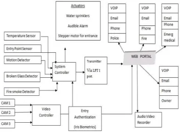
The microcontroller used for this design is the Atmel 8051, which is an 8 -bit processor chip optimized for control applications. The basic security subsystem is shown in figure 1.
Figure 1: System block diagram
Fire detection is used to detect and alert against a possible fire outbreak. It incorporates smoke detectors and temperature sensors. Smoke detectors detect presence of smoke particles as an early indication of fire. Temperature sensors measure temperature levels in test areas and indicate when the temperature becomes very high. It protects against significant property damage and risks to life within the property.
The alarm system unit makes use of a simple buzzer for audio alert in case any detector is triggered. The PC central
monitoring unit is entirely software based and forms the control and display unit of the entire security system. Detectors are monitored via the display. Access control can be monitored and access logs stored on its database.
1.2 THE CONCEPT OF A WEB BASED SECURITY SYSTEM
Internet from any place in the world. This is the web based Security System. With the world becoming a global village [4], the feasibility of communication over long distances has been improved owing to the internet, with attributes such as mails, voice over the internet protocols (VOIP), live chats, web portals and many of such components that make up the global village. Keeping watch over valuable property, homes, and industries from any part of the world could be achievable via the internet , the concept provides a system for detecting an event within a premises and providing data such as live or recorded video and audio, details of the status of units measuring physical quantities and referring such event to a portal. Video signals are fed directly to the monitoring units which are integrated into the web based monitoring system and can be monitored by the PC security application.
1.3 HARDWARE MODULE ORGANIZATION
The hardware module was designed to consist of the following units as explained below:
INTRUSION DETECTOR UNIT
A pyroelectric infrared sensor is used for our intrusion detection, because from our research, pyroelectric infrared sensor is found to have a higher degree of detection than other intrusion detectors like photoelectric beam sensors and infrared sensors. The pyroelectric sensors exhibit high sensitivity and reliable performance [5]. It detects any intrusion within a restricted area.
TEMPERATURE SENSOR UNIT
In order to conform to the out lined factors, the LM35 is used; the LM35 is a precision integrated circuit temperature sensor whose output is linearly proportional to the Celsius (Centigrade) temperature [6]. The LM35 does not require any external calibration or trimming to provide typical accuracies of ±¼
ºC at room temperature and ±¾ ºC over a full -55 to +150ºC temperature range
THE SMOKE DETECTOR UNIT
The MC145012 CMOS IC is the smoke sensor used [7]. It is a smoke detector (photoelectric detector) component containing sophisticated very low-power analog and digital circuitry. Detection on this device is accomplished using IR (photodiodes) detectors that are directly interfaced to the CMOS IC to sense the presence of scattered light, this is accomplished with the help of a smoke box – a hollow box with slits at its edges and a matt black coated inner surface. It has a lamp and a photodiode separated by a screen. Normally, the opaque screen blocks light from reaching the LDR. The black surface also prevents reflection over the screen. As smoke enters the room, the temperature heats the air in the chamber which rises up drawing the smoke filled air through the lower chamber. The smoke particles help in scattering light thereby allowing light to fall on the photodiode and activating it. The photodiode is connected to a comparator circuit which gives a signal if the threshold value is exceeded. The threshold is variable hence the smoke sensor has adjustable sensitivity.
THE SURVEILLANCE UNIT
NIGERIAN JOURNAL OF TECHNOLOGY, VOL. 29 NO 2, JUNE 2010 ENCODER AND DECODER UNIT
The RF 600D and RF600E were chosen because of the high security level built into both ICs. This is because the RF600D can only decode information encoded by an RF600R it already knows about [9]. The RF600E requires first external switches to be able to encode four channel signals into a serial string of codes. The encoder provide s a serial input of six words for hard wired, infrared or fibre optic communication links. Channel adds logic is provided to control the number of encoded channels from three to six, allowing increased design flexibility.
THE TRANSMITTER AND RECEIVER UNIT An AM hybrid transmitter module (AM -RT4-433) is a complete transmitter on a board without a need for external components. It operates in the free frequency range of 433MHz unlike some other transmitters like AM-88 and AM-25 that transmit at medium wave (5301710 kHz) and a long wave (150 -285 KHz) [10]. It has a very high frequency stability hence removing the fear of frequency drifts during operation. It is not expensive and therefore, it was used. The model is very simple to operate and offers a low current consumption. A hybrid receiver (AM -HRR-433MHz), captures un-decoded data from the transmitter. It is a full receiver on a board hence relieving us of the job of having to do add other components to the receiver IC. The ICs work at 433MHz frequency which falls into a free range of frequencies. These modules show very high frequency stability over a wide operating temperature even when subjected to mechanical vibrations.
THE DATA PROCESSING UNIT
The data processing unit functions as the central monitoring unit and PC interfacing unit for the hardware model. The unit continuously scans the other con nected sub-modules for signals which are then organized and sent to the PC through an interface. For easy integration of monitoring and interfacing activities, a programmable controller is
necessary. Atmel AT89C51 microcontroller is employed here [11]. The choice of this chip is based on cost, availability of development tools and familiarity with the instruction set.
1.4 SOFTWARE MODULE ORGANIZATION
The PC interface application software should possess the following capabilities:
Ability to handle data collection from microcontroller based security system; logging of access times
Ability to integrate security camera hardware module and display video Audio-visual representation of ingress
and egress with access control system Virtual instrumentation for
sensors/transducers and audiovisual alert upon triggering
Based on these functions, the software is divided into modules which interact using a top-down, object oriented design approach. This modular application can be designed optimally using a programming language that has the following characteristics:
Object Orientation Port interfacing Network capability
Web based Graphic User Interface mode
1.5 DATA ACQUSITION UNT DESIGN AND IMPLEM ENTATION
The hardware module is made up of various sub modules connected to the microcontroller unit. These sub modules were designed to function independently and include the input module, the output module and the control module. These modules are further broken up into smaller independent sub modules. This type of design makes the circuit easier to understand, easier to troubleshoot and also eases implementation.
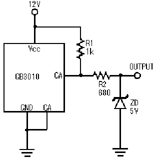
THE BROKEN GLASS DETECTOR UNIT
Using Security Centre GB3010 glassbreak detector [13], the following circuit was designed as shown in figure 2. The glassbreak detector has a resistance of 25Ω between its CA outputs when the sensor is inactive. This resistance increases to 1MΩ on triggering. Using a 1KΩ resistor from one of CA outputs to Vc c ensures that we have logic zero output when the sensor is inactive and logic one when the sensor is triggered. This is seen using the voltage divider rule. When the sensor is inactive it presents a resistance of 25Ω in series with R1 [14].
Hence our output voltage is:
; 3 . 0 12 1025
25
0
V
This is in the logic low level range for standard logic. On triggering, our output voltage becomes:
V k
M M
V 12 0.3
1 1
1
0
;
This is way above standard high logic level. To bring this down to 5V we use a 5V zener diode. To obtain the value of the dropping resistor R2 we let current of 10mA run through the diode. Thus the value of the voltage that needs to drop is (1 2-5) V, R2 value should be:-
700
10 ) 5 12 ( 2
mA V R
The standard resistance value closest to this is 680Ω hence, the value of R2.
NIGERIAN JOURNAL OF TECHNOLOGY, VOL. 29 NO 2, JUNE 2010 SMOKE DETECTOR UNIT
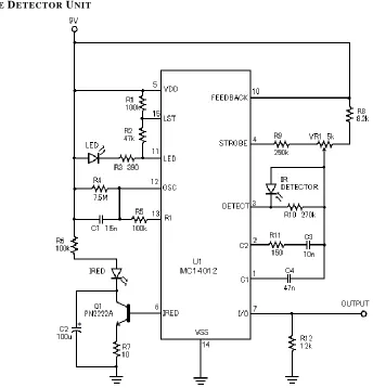
Figure 3: Circuit Diagram of Smoke Detection sub module
We made use of the MC14012 Photoelectric Smoke Detector IC and photodiodes to detect scattered infrared light from smoke particles. This infrared light is generated by an InfraRed Emitting Diode (IRED). The IRED is powered by the Smoke Detector IC through a transistor with the he lp of its on chip oscillator with period T, determined by R1, R4 and C1 with the formula:
T = 0.6931(R1 + R4)C1
With the values used as shown on the circuit diagram of the smoke sensor in figure 3, we have our period to be 7.9ms giving an oscillating frequency of 126Hz.
The signal from the photodiode is amplified by an on-chip amplifier and compared against a reference 3.5V by an on -chip comparator to enable the smoke detector comply with the UL217 and UL268 specifications.
The Smoke Detector IC also pulses current into the LED in the circuit diagram to enable it flash visible light at preset intervals as required by the above listed smoke specifications.
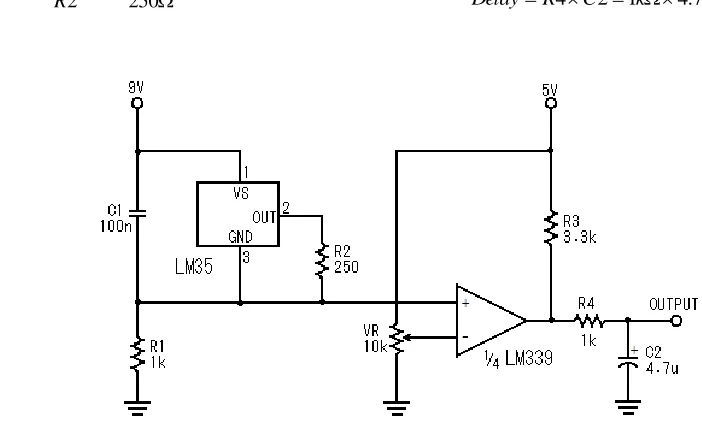
TEMPERATURE SENSING UNIT
with the help of the LM339 comparator as shown in figure 4. The LM35 is a device that produces a linear 10mV/ºC output between its output and ground pin with a value of 250mV at 25ºC. Resistor R2 which has a value of 250Ω placed across these pins causes a current of 1mA to flow from output pin to ground pin. When this 1mA current flows into the 1kΩ resistor a voltage of 1V is generated across it.
mA mV R
mV
Is 1
250 250 2
250
This gives a ×4 scale factor. This means that the voltage at the non -inverting input of the comparator changes at 40mV/ ºC. The reference voltage which the temperature sensing output is compared with is set with the help of VR which has a value of 10KΩ. R3 serves as a pull up resistor for the comparator output. The RC network formed by R4 and C2 serves as a 4.7ms time delay to prevent against false triggering of the temperature sensing unit.
ms F
k C R
Delay 4 214.7 4.7
Figure 4: Circuit diagram of temperature sensing unit
PYROELECTRIC INTRUSION DETECTION UNIT For this unit we made use of the Murata IRA-E700 Pyroelectric Infrared sensor to detect the presence of humans. The circuitry for this unit is shown in figure 5. “On detecting the infrared radiation emitted by humans it gives an alternating voltage with a possible maximum value of 4.3mVp -p. This signal is then amplified by two operational amplifiers, (1/4 and 2/4 LM324), one in the non -inverting mode and the other in the inverting mode respectively. The gain of both opamps is
determined by R3, R4 and R8, R9. This gives us an approximate gain of
8 9 4 3
R R R
R
NIGERIAN JOURNAL OF TECHNOLOGY, VOL. 29 NO 2, JUNE 2010
Fig. 1.5 Circuit diagram for pyroelectric intrusion detection unit
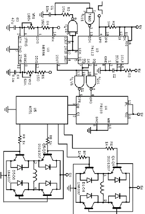
DOOR CONTROL UNIT
A stepper motor control circ uitry was designed using basic logic circuitry as shown in figure 6. The circuitry was designed to use the stepper motor to open a door, leave it
Fig 6 Circuit Diagram of Stepping Motor Controller
RECEIVER,TRANSMITTER,ENCODER AND DECODER DESIGN
Using standard IC packages these parts of the system where designed. Information from sensors is sent wirelessly to the microcontroller. In order to make use of a single channel for transmitting the sensors information, an encoder is used to encode information from the four sensors. The
NIGERIAN JOURNAL OF TECHNOLOGY, VOL. 29 NO 2, JUNE 2010 1.6 DATA PROCESSING UNIT DESIGN AND IMPLEMENTATION
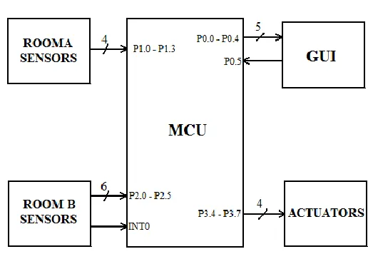
Figure 7 Microcontroller connection design for security system
The hardware sub modules are all connected to a microcontroller unit (8951) for processing and transfer to the PC GUI [15], via the interface unit as shown in figure 7.
1.7 SOFTWARE DESIGN AND
IMPLEM ENTATION.
The PC interface application software possesses the following capabilities:
Ability to handle data collection from microcontroller based security system; logging of access times
Ability to integrate security camera hardware module and display video Audiovisual representation of ingress and
egress with access control system
Virtual instrumentation for sensors/transducers and audiovisual alert upon triggering
Based on these functions, the software is divided into modules which interact using a top-down, object oriented design approach. This modular application can be designed optimally using a programming language that has the following characteristics:
Object Orientation: Object-Oriented Programming (OOP) is a high-level computer language that uses self
-contained, modular instruction sets for defining and manipulating aspects of a computer program. These discrete, predefined instruction sets are called objects and they may be used to define variables, data structures, and procedures for executing data operations. In OOP, objects have built-in rules for communicating with one another. By using objects as stable, preexisting building blocks, programmers can pursue their main objectives and specify tasks from the top down, manipulating or combining objects to modify existing programs and to create entirely new ones. This greatly reduces the stress in the development of the software.
Port interfacing: The software is able to read the signals from the microcontroller through the parallel port interface store it and be able to recall when it is needed by the user.
different locations as long as they have internet access.
Graphic User Interface mode: is a type of user interface item that allows people to interact with programs in more ways than typing such as computers; hand -held devices such as MP3 Players, Portable Media Players or Gaming devices; household appliances and office equipment with images rather than text commands. A GUI offers graphical icons, and visual indicators, as opposed to text -based interfaces, typed command labels or text navigation to fully represent the information and actions available to a user. The actions are usually performed through direct manipulation of the graphical elements. Since the security system is web based, the Graphic user Interface mode is a portal.
1.8 CONCLUSION
The security system was designed to be a simple model showing possible incorporation and integration of different security systems into a single unit with central monitoring. Based on this objective, the design was restricted by economic and spatial factors.
This design is an upgradeable model with possible upgrades or enhancements of the model that could include:
Universal Serial Bus (USB) port interfacing – although more complex than the parallel port, USB has the advantage of being fast and convenient. Moreover, with the parallel port slowing becoming obsolete in the new technological era, the USB port has to be embraced.
More secure access card system – the use of a more sophisticated and efficient card system to reduce or eliminate forgery and false authentication.
Programmable Logic Devices (PLD) – The use of PLDs to replace the Transistor-Transistor Logic (TTL)
increases the circuit capability and reduces the space required (a circuit consisting of many TTL ICs can be
programmed on a single PLD) [16] as
well as development time.
Incorporation of more security subsystems – other security systems can be added to the central monitoring unit. These systems could include fingerprint authentication systems, production control systems, voice recognition systems, and others.
REFERENCES
1. Wikipedia Free Online Encyclopedia. http://en.wikipedia.org
2. Gibilisco, Stan. The Illustrated Dictionary of Electronics. 8t h ed. New York: Mc-Graw Hill, 2001
3. Daugman, J., How Iris Recognition Works, http://www.ncits.org/tc_home/ m1htm/docs/m1020044.pdf
4. http://www.iicd.org/articles/IICDnews.im port9/
5. Pyroelectric Infrared Sensors Infrared Sensors, http://www.murata.com/ products/catalog/pdf/s21e.pdf
6. LM35: Precision Centigrade Temperatur e Sensor,
http://www.national.com/mpf/LM/LM35. html#Overview
7. MC145012: Photoelectric Smoke Detector IC With I/O And Temporal Pattern Horn Driver/
http://www.datasheetdir.com/MC145012 +Smoke-detectors
8. Axis network cameras,
www.axis.com/files/brochure/bc_netcams _34690_en_0903_lo.pdf
9. RF / IR Encoder / Decoder Chipset RF Evaluation Boards,
www.rfsolutions.co.uk/acatalog/DS600 -10_RF600.pdf
10. AN242 Designing an FCC Approved ASK rfPIC Transmitter,
NIGERIAN JOURNAL OF TECHNOLOGY, VOL. 29 NO 2, JUNE 2010 11. 8-bit Microcontroller with 4K Bytes
Flash AT89C51, www.atmel.com/atmel/ acrobat/doc0265.pdf
12. Programming Languages in ASP.NET,
http://msdn.microsoft.com/en-us/library/fbdt8kk7(VS.80).aspx
13. Accesscontrol,detector,glass,break,brown ,Vds,GB3010B, http://docs-asia.origin. electrocomponents.com/webdocs/0641/09 00766b80641451.pdf
14. http://www.epanorama.net/links/motorco ntrol.html