118
Available online at www.ijiere.com
International Journal of Innovative and Emerging
Research in Engineering
e-ISSN: 2394 - 3343 p-ISSN: 2394 - 5494
A State-of-Art Review of Structural Response Control
Methods
Dr. Ajay K. Sinha
aand Sharad Singh
baProfessor and Director, Earthquake Safety Clinic and Centre, Department of Civil Engineering, National Institute of Technology, Patna, India
bResearch Scholar, Structural Engineering, Department of Civil Engineering, National Institute of Technology, Patna, India
ABSTRACT:
The elementary purpose of seismic protection systems is to prevent the structure from absorbing seismic energy by limiting the entrant seismic energy or transferring it to an energy dissipating system. In this field, serious efforts have been undertaken to advance the structural control concept into a workable technology, and today many such devices have been installed in a wide variety of structures. This paper reviews development in the field of response control and seismic protection systems that have been incorporated in structures for control of seismic vibrations.
The focus of this state-of-the-art paper is on the advancements of structural response control systems. A brief historical outline of their development and an assessment of the state-of-the-art of this exciting and evolving technology have been undertaken in this study. Along with seismic applications, a discussion about their advantages and limitations in the perspective of seismic design and retrofit of civil engineering structures has also been discussed. It also addresses the details of various control methods along with various device categories and effects on dynamic behavior and performance of structure.
Keywords: Response control, classification, base isolation, energy dissipation, passive and active system, development and attributes.
I. INTRODUCTION
The human history has witnessed several catastrophic earthquakes, leading to enormous loss of life and property and untold sufferings. Eminent work has been done to prevent the collapse but allowing minor damages in structure as such as to minimize the loss of life and property. The experiences of past earthquakes have provided sufficient evidences about performance of different structures under various conditions as working ground for engineers and scientists [5]. The modification of structural systems carried out to reduce vibrations has conducted towards the concept of structural response control [3]. This means that the structure is regarded as dynamic system whose response variables are functions of time and in which some mechanical properties such as stiffness and damping may be adjusted to minimize the dynamic effects of load under an acceptable limit [1, 4]. The control of structures to improve their performance during earthquakes was first proposed more than a century ago. But it has only been in the last 30 years that structures have been successfully designed and built using earthquake protective systems. Today these systems range from simple passive devices to fully active systems. Major developments in the theory, hardware, design, specification, and installation of these systems have permitted significant applications to buildings, bridges, and industrial plant. Noteworthy advantages have been demonstrated when retrofitting existing structures, and designing high-performance structures such as hospitals, emergency response facilities, defence installations, and critical bridges [7, 9].
119 on kinematic interaction is modification of dynamic characteristics of structure for response control and on the basis of dynamic interaction is modification of energy absorption mode of response control [1, 2, 3].
A. Modification of dynamic characteristics [3]
Based on kinematic interaction mechanism the structure under dynamic character modification is isolated from ground motion. Based on this concept the superstructure is decoupled from base as such the inertia of structure against ground motion or base movement is controlled. This prevents or limits entrant seismic energy into the superstructure. The structural period of vibration shifts towards lower side of vibration mode and avoids resonance with seismic vibration frequency. The resonance of ambient frequency with forcing frequency is catastrophic which is avoided in this mode of response control. It is effective over a limited range of frequencies as seismic excitation is random and contains a sequence of random frequencies. Hence in advance knowledge of frequency content of seismic wave is required for accurate implementation of this mode of response control. In addition to frequency shift due to isolation of base a lateral motion is generated in compensation for frequency shift. As a result the entire structure moves horizontally and no inertial force is generated which protects structure against damaging effects.
B. Modification of energy absorption [3]
Based on dynamic interaction mechanism the structure under energy absorption modification is based on dissipation of entrant energy. In this concept the structure is coupled with energy dissipating devices. The seismic energy is allowed to enter the structure which is consequently shared by energy dissipating devices as such overall load carried by the structure is reduced and hence the response is controlled. Energy is dissipated by damping and inelastic deformations which form the criteria for energy based design of earthquake resistant structure. It is applicable to any range of forcing frequency as accordingly the frequency is distributed in the control system unlike the former mode of frequency shift. The problem of lateral motion generation is eliminated in this mode as such it provides ease and comfort to users.
II. CATEGORICAL IDENTIFICATION OF EARTHQUAKE PROTECTION SYSTEMS
Following the concept of response control via modification of either dynamic characteristic or energy absorption characteristic the earthquake protection systems have been broadly categorized into [9]
1. Base Isolation systems which follow the modification of dynamic characteristic. 2. Energy Dissipation systems which is based on modification of energy absorption. 3. Tuned systems which incorporate both.
The objective of this classification is to identify various devices and systems into above listed categories.
III.BASE ISOLATION SYSTEMS
Base isolation proposals have been made for more than a century. Kawai in 1891 proposed isolation with timber logs placed in several layers in both longitudinal and transverse directions. However the concept was coined with the implementation of thick mud layer for isolating “Imperial Hotel” structure in Tokyo by Frank Lloyd Wright around 1923, thereafter several methods of isolation have been developed world over. The base isolation is achieved by introduction of low stiffness bearings and dampers between the superstructure and the foundation. Bearings tend to make the combined system more flexible and hence shift its first mode natural frequency away from predominant frequency of earthquake motion, thereby reducing inertial forces and accelerations. The response of isolated structure reduces to ½ o 1/8 of the traditional structure. Whereas the dampers provided in the system absorbs energy and prevents entry of seismic energy into the superstructure [6].
Various known isolation systems have been discussed below. A few techniques which due to one or more short comings and impracticality, which have not been readily adopted and no longer in use have also been listed [6].
A. Layers of longitudinally and transversely placed timber logs, Kawai
B. Mud layer below the structure- Imperial Hotel structure (Tokyo), Frank Lloyd Wright (1923).
C. Flexible first storey- technique was proposed by Martel and later studied by Green, Jacobson and finally Chopra et.al. showed the concept being impractical.
The modern base isolation technique dates back to as early as 1960.
D. Roller bearings in foundation
This system (Figure 1) was a development over the Kawai’s proposal of timber logs, but had serious drawback of lateral motion generated in one direction only. The seismic waves having three directional motion raised question over effectiveness of this isolation system as well as the system demanded maintenance over the working life period [6].
120
Figure 1 Cylindrical Roller Bearings
Figure 2 BS Cushion with displacement joint
Figure 1Source:https://encrypted-tbn0.gstatic.com/images?q=tbn:ANd9GcQ_kcx4MNGb8eiaPYEbPYLmBazJVVeXLYt1Kdh4ypFQSgcucFRd Figure 2 Source: X. Chen; Behaviour analysis and application research for treated asphalt-fibre seismic isolation cushion; Proceedings of 13th world conference on earthquake engineering; August 2004; Paper no. 1959.
E. Elastomeric bearings [6, 8]
Rubber layer as foundation support for school building in Skopje (Yugoslavia) - 1969, bounced and rocked during earthquake, being attributed to uniform stiffness of rubber. Also the foundation bulged under the dead load. To overcome the problem of bounce and rock as well as adopt the flexibility attributes of rubber elastomeric bearings were proposed. Today a wide variety of elastomeric bearings are available, each with some modification over the other.
1) Laminated rubber bearings (LRBs)
LRBs are made as thin steel plates and rubber in layers one over the other (Figure 3a). The elastomer provides the horizontal flexibility whereas the steel plates fulfil the need of desired vertical stiffness. The behaviour of LRB during a dynamic loading has been represented in (Figure 3b), and the curve takes various shape changes with change in LRB material. With the advances in polymer technology various elastomers have been used to device LRBs. Superiority in mechanical properties of natural rubber over synthetic rubbers makes it most suitable elastomer and hence most frequently recommended material for a LRB but several other elastomers with modification over natural rubber are also used to suite specific needs. Neoprene rubber, butyl rubber, nitrile rubber and KL301, a blend of high damping rubber, are few synthetic rubbers often employed in LRBs. To improve the horizontal stiffness and damping properties filler agents like metal oxides, clay, cellulose and carbon black are employed in compounding the elastomer. The steel plates are laminated with elastomers by a fully vulcanized process with steel plates being coated with adhesives before they are placed in a mould containing un-vulcanized elastomer [6].
a) Laminated Rubber Bearing, sectional detail b) Hysteretic Force-Displacement curve for LRB Figure 3a) Source: http://www.mdpi.com/buildings/buildings-02-00300/article_deploy/html/images/buildings-02-00300-g001-1024.png
Figure 3b) Source: http://www.bridgestone.com/products/diversified/antiseismic_rubber/images/img_product_29.gif Figure 3
Various design shapes and laminations have been adapted to suit structural demand. LRBs are available in rectangular, square, circular, skewed and tapered shapes. They are also designed as elastomeric bearing pads, anchored LRBs, and some with additional damping and motion control features with friction slides and vertical stiffeners provided.
2) New Zealand bearing system [6]
121
a) Sectional view: New Zealand bearing (b) hysteresis loop for New Zealand bearings Figure 4a) Source: https://encrypted-tbn0.gstatic.com/images?q=tbn:ANd9GcQ6_93nSQpXlNQEWarG6yK_UGQwewpLA0v_OUcRlJHgPnkc1mN
Figure 4b) Source: https://www.researchgate.net/profile/Zamin_Jumaat/publication/229045386/figure/fig4/AS:300784353857540@1448723986400/Figure-6-Idealized-force-displacement-Hysteresis-Loop.png)
Figure 4
In one such modification the lead core plug is replaced with rubber core plug with steel rod within and the rubber steel laminate is replaced with concentric layers of Teflon coated steel plates. The system popularly known as Resilient-friction base isolation (R-FBI) system was proposed by Mostaghel and Khodaverdian. The laminates provide friction in form of sliding resistance and rubber the necessary resilience. It is a combination of sliding friction and elastomeric bearing system.
3) BS cushion isolation [26]
Treated Asphalt-Fiber Seismic Base Isolation Cushion, popularly known as BS cushion (Chinese Patent Number ZL99202381.5) invented in 1999 Hangzhou (China) is identical to LRB. Fiber and treated asphalt in BS Cushion play similar role as steel plate and rubber in LRB. The Cushions were laid with alternate layers of sand in 4 layers for a 7 storey masonry- concrete structure. The system has moderate isolation effects, with fundamental period of building shifting from 0.3 sec to 1 sec, but has the advantage of low cost and unlike LRBs which has point application, BS cushions separate bearing walls over the length from the foundation (Figure 2). Previous experimental results have shown a moderate isolation (35% to 50%) achieved by BS cushion. But the technique needs improvement in design philosophy and material as well as in modelling and calculation approach.
F. Friction Bearings [6]
Since one of the damping mechanisms in structures is due to friction of joints and internal friction of deforming solids. This phenomenon has been utilized in design of a different kind of isolation system called friction bearings.
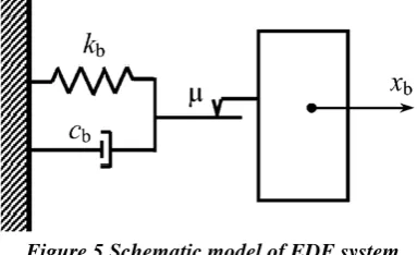
1) Electric de-France system (EDF)
Developed under the aegis of Electric de-France in 1970, the system is a friction type base isolation system. Initially the system was standardized for nuclear power plants in regions of high seismicity. The device is fabricated as laminated Neoprene pad topped by a lead bronze plate, and is in frictional contact with steel plate which is anchored to the base raft of the structure. The cross section is identical to LRB system, where the laminated neoprene pad has low displacement capacity and as this exceeds the sliding element, controlled by friction between top lead bronze plate and anchored steel plate (Figure 5), provides the necessary movement. However the system did not incorporate any restoring device to prevent permanent displacement [6].
Figure 5 Schematic model of EDF system
Source: https://www.researchgate.net/profile/Vasant_Matsagar/publication/222683485/figure/fig2/AS:349580697849864@1460357941937/Fig-2-Schematic-diagrams-for-LRB-N-Z-P-F-FPS-R-FBI-and-EDF-systems.png
2) Sliding resilient-friction system
122 It is usually modelled as a spring system and can be used either in parallel or series, and the combined system is modelled
as a bilinear hysteric system
(Figure 6) [6, 27].
Figure 6 Sliding resilient friction system: representative model and hysteresis loop
Source: H. Iemura, and T. Tagnikhany; Optimum design of Resilient sliding isolation system to protect equipments; Proceedings of 13th world conference on earthquake engineering; August 2004; Paper no. 1362.
3) Pure friction base isolation system
In a pure friction base isolation system the aim is to develop frictional force by provision of sand layers or rollers at the base, which dissipates the seismic energy. It was developed for low rise structures in China. This system has usefulness over a wide range of frequency inputs. Though the system has the advantage of being cheap but alike the above frictional systems it lacks the capability of lateral displacement recovery as well as in case of sand layer as base isolation the system is sensitive to foundation settlement [6].
To improve upon the shortcomings of afore mentioned arrangements of pure friction base isolation system, M.K. Yegian and U. Kadakal suggested pure friction base isolation arrangement using geo-synthetic material. The arrangement followed placing a high strength non-woven geo-textile over an ultrahigh molecular weight polyethylene. It is noted that the coefficient of static friction between the two materials is 0.1 and have a dynamic friction coefficient of 0.7. Hence a geo synthetic over a liner dissipates seismic energy in sliding friction. It is suggested to keep the sliding friction between the two materials in a range of 0.05 to 0.15. Even though this arrangement is efficient enough to isolate seismic force from entering superstructure it as well needs external support system to mitigate the issue of lateral displacement [6].
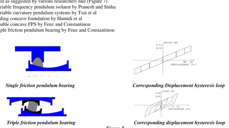
4) Friction pendulum system (FPS)
FPS combines geometry and gravity to achieve desired seismic isolation and is based on the principles of pendulum motion. By using the characteristics of a pendulum it lengthens the natural period of the isolated structure so as to avoid the strongest earthquake forces. During an earthquake, the supported structure moves with small pendulum motions. Since earthquake induced displacements occur primarily in the bearings, lateral loads and shaking movements transmitted to the structure are greatly reduced. The frictional damping absorbs the seismic energy [6, 28].
This system is an improvement over all other systems and is individually efficient and capable of isolating seismic forces as well as control lateral displacement. FPS is efficient and cost effective device in seismic isolation and it simply alters the force response characteristics of the structure at base isolation level. Varieties of FPS design have worked out and are used as suggested by various researchers like (Figure 7)
a) Variable frequency pendulum isolator by Pranesh and Sinha b) Variable curvature pendulum systems by Tsai et al
c) Sliding concave foundation by Hamidi et al d) Double concave FPS by Fenz and Constantinou
e) Triple friction pendulum bearing by Fenz and Constantinou
Single friction pendulum bearing Corresponding Displacement hysteresis loop
Triple friction pendulum bearing Corresponding displacement hysteresis loop Figure 7
Source: http://earthquakeprotection.com/triple_vs_single_pendulum.html
123
G. Spring type systems [6]
Elastomeric and friction based isolation is effective in horizontal direction only. Hence for a 3 dimensional isolation a spring type system was suggested for two steel framed structures in Santa Monica (California). The system with large helical steel springs having flexibility in horizontal as well as vertical direction was developed under the brand name of GERB, and was used in association with GERB viscous dampers. The structure was affected by Northridge earthquake (1994) as the monitored response showed that system was not effective in reducing acceleration due to rocking motion.
H. Rocking systems [6]
Tall slender structures with heavy top mass invariably develop overturning moments leading to development of tension in foundation. Providing tension capacity to foundations in weak soil being difficult and anchorage a costly affair, the solution to the problem was sought as allowing the lifting of columns or piers from foundation. The partial isolation in this manner reduces seismic load throughout the structure. This system involves complexities in analysis and design and for this reason the application is limited to a railway bridge on south Rangitikei River, New Zealand (1972). In the structure 69m long piers have been designed to lift under seismic load, with energy dissipaters (based on elastic plastic torsion of mild steel bars) provided inside each pier.
I. Sleeved pile isolation system [25]
Considering the importance of pile foundation in soft soils (up to large depths) the sleeved pile isolation technique is useful from seismic point of consideration. In the system a casing is provided around the pile and gap is maintained between pile and casing to allow sway of the pile under effect of ground motion, whereas the pile is supported and anchored to the hard rock strata below. The Union House, a 12 storey structure in Auckland (New Zealand, 1983) used this system (10m deep piles enclosed in steel casing). With this system the building has a period of 4 seconds.
IV.ENERGY DISSIPATION DEVICES (DAMPERS)
As has been stated earlier the energy dissipation mechanism is based on modification of energy absorption [3], any structural system under dynamic loading, the entrant energy is dissipated naturally by various damping mechanisms acting simultaneously [1, 3, 4]. The thermal effect of repeated elastic straining, internal friction when solid deforms, friction at joints and opening and closing of micro cracks are the known mechanisms dissipating vibrational energy. As the mathematics of the mechanism behaviour in damping is not precisely known, the collective damping phenomenon is idealized as viscous damping within the linear elastic limit of the deformation and estimated by studying the response of the structure. Sometimes damping in structural system is attributed to static hysteresis which is rate independent linear damping and is non-viscous in nature. Apart from viscous damping vibrational energy is also dissipated by macroscopic plastic deformation and yielding of material and even due to friction of structural system. This damping is non-linear in nature and observable in the inelastic behaviour of the considered structural system. The damping due to friction of the structural system is called as coulomb friction damping. All the damping mechanisms are hysteretic in behaviour but with some differences in the hysteresis loop [22]. All these damping mechanisms have been utilized individually or in combination to design and develop various categories of energy dissipating devices stated below [1, 3, 10].
The dampers have been in use for long time but there major application was known only to field of mechanical systems, piping systems, automobiles and aerospace. The application to structural systems to resist wind and earthquake induced vibration has only been known for a couple of decades only after pioneering investigations of Housner on energy balance approach for design procedure [12, 21, 22].
A. Viscoelastic Dampers (VED)
124 Figure 8 Visco-Elastic dampers Figure 9 Viscous or Fluid Viscous Dampers
Figure 8 Source: http://pressurevesseltech.asmedigitalcollection.asme.org/data/journals/jpvtas/28414/013201j.6.jpeg Figure 9 Source: http://taylordevices.com/papers/history/design/design.gif
B. Viscous/Fluid viscous dampers (VD/FVD) [7, 11, 13, 21]
The idealization of structural damping to equivalent viscous damping has motivated developers to use the viscous property of fluids into developing FVDs. In a VD wall system developed by Sumitomo Const. Company (Tsukuba, Japan; 1987), attached to lower floor the device consists of an outer steel casing filled with high viscosity liquid and an inner steel movable plate hanging from upper floor. The shear resistance of fluid controls the inter storey drift and a response reduction of up to 80% was observable. The principle of fluid flow through orifice has also been exploited to develop FVD, which possess linear viscous behaviour and are insensitive to temperature variation. One such type of FVD developed by Taylor Devices, Inc. [21, 29] (Figure 9) consists of stainless steel piston with bronze orifice head, an accumulator and is filled with silicone oil. The performance of the FVD can be altered by altering temperature, the orifice shape and size and by controlling the fluid flow behaviour for seismic application suitability. The FVDs are more efficient in reducing storey and base shear, up to 70%, and the damping force is out-of-phase with displacement thereby peak induced column moments are less during peak displacement in diagonally braced system. However maintenance is an issue over time [21].
(a) (b)
Figure 10 Hysteretic Force-Displacement curves for a) VED and b) VD/FVD Figure 10a Source: http://ascelibrary.org/cms/attachment/11970/280198/figure6.gif
Figure 10b Source: http://ars.els-cdn.com/content/image/1-s2.0-S0022460X13007293-gr1.jpg
The dependency of FVDs on velocity and insensitivity to frequency content makes them inefficient in reducing peak structural response in early stage of excitation. The shortcoming was resolved using tapered plate energy absorber. To note in this category is an exciting innovation called Magneto Rheological (MR) Fluid Dampers.
C. Friction Dampers (FD) [12]
125 and it consists of frictional and distribution washers bolted to steel plate [17]. The efficiency of the device depends on material and dimension of washers.
Another attempt of FDs was made by Sumitomo metal industries of Japan and is called as Sumitomo FD or Dissipative strut (Figure 11a). It has been designed as copper pads impregnated with graphite and in contact with steel casing, where the contact surface is developed between Belleville washer/Cup Springs and a series of wedges [12]. Graphite acts as lubricant and ensures constant frictional coefficient. Translational FDs like Pall FD and Sumitomo FD depend on ground motion and hence for small excitation they do not slip and dissipate energy. Moreover the base shear is not significantly influenced. More recently a version of dissipative strut referred to as friction based ring spring damper created by assembling cylindrical wedges/rings in series to form friction spring (Filiatrault et.al, 2000) produces a flag shaped hysteresis loop and are effective in reducing lateral displacement [15]. But the sophistication, hardware and cost limit its adaptability.
Figure 11a Sumitomo Friction Damper Figure 11b Pall Friction Damper Figure 11a Source: http://ascelibrary.org/cms/attachment/163398/2824901/figure11.gif
Figure 11b Source: https://encrypted-tbn1.gstatic.com/images?q=tbn:ANd9GcTpbIOmmzRKdMaKrSt89_15aMEy4mCvbDqaXmBJDpRwvSXIwZeO3g
A slotted bolted connection (SBC) made of two back to back channels, gusset plate, cover plate, bolts with Belleville washers and steel sliding interface or brass and steel sliding interface is a simplification over limitations of afore mentioned FDs (Figure 12) [12].
(a) SBC side view SBC: sectional view (b) SBC top view Figure 12
Figure 13 Hysteresis loops for EDR
Source: Fahim Sadek, Bijan Mohraz, A.W. Taylor, and R.M. Chung; Passive energy dissipation devices for seismic application; NISTIR 5923, National institute of Standards and Technology, USA; November 1996
126 permanent deformation beyond elastic range. FDs possess shortcomings in terms of precision, material, installation and operation cost, corrosion susceptibility, wear and tear, and permanent offsets has invited improvements for simplicity and economical design [12].
Some of these FDs were modified and improved to act as seismic isolators.
D. Metallic Dampers [12]
The structure collapses due to yielding of the structural system. The yielding phenomenon is represented by hysteretic behaviour in the inelastic range. Metallic dampers exploit this attribute of metals to share the load and yield out before the structure yields and collapses. Flexure, shear and extensional deformation in plastic range have been deployed to design various devices of this category. Apart from long term reliability, stable behaviour and resistance to environmental and thermal conditions they provide structural system with increased stiffness, strength and energy dissipation capacity.
(a) (b)
Figure 14 Generalized Hysteretic Force-Displacement loops for a) Yielding MD and b) Friction Dampers Source: Fahim Sadek, Bijan Mohraz, A.W. Taylor, and R.M. Chung; Passive energy dissipation devices for seismic application; NISTIR 5923, National institute of
Standards and Technology, USA; November 1996
1) Yielding Dampers [12]
As early as 1965, Guerrero proposed yielding device as a system of peripheral metal bands to protect infill walls of frame systems. The arrangement is cumbersome and expensive and not much effective in protecting the structure as a whole. The improvement over this proposal was the slitted RC wall for a tall building in Japan acting as a series of RC columns. The energy is dissipated by formation of plastic hinges due to inelastic deformation behaviour during inter-storey deflection. But due to huge dead load adding to inertia, cost of repair, permanent damage during a major event and low ductile efficiency of the system it has not been further recommended. Development of yielding devices at Physics and Engineering laboratory (PEL, New Zealand, 1970s) pioneered devices relying on bar yielding. The yield properties of mild steel suit the requirements for design of such a device. Various yielding dampers like Torsion beam hysteretic damper, tapered round steel cantilever, Flexural beam damper and bent mild steel bars have been suggested. Most of these developments were result of developments for base isolation system. Furthermore the yielding of metals has been extended from metal bars to metal plates. This has been utilized to propose a flexural damper using U-shaped steel strip rolled between relatively moving parallel surfaces. The oval element yield device is advancement over the U shaped steel strip. A simple alternative to torsion beam type, the tapered plate device is suggested to protect braced systems against buckling and yielding [14].
127
(a) TADAS device: sectional view Figure 15 (b) Hysteresis loop for an ADAS
Source: Fahim Sadek, Bijan Mohraz, A.W. Taylor, and R.M. Chung; Passive energy dissipation devices for seismic application; NISTIR 5923, National institute of Standards and Technology, USA; November 1996
Also the proposals of yielding frames by David Smith and Robert Henry for braced systems has been studied and developed. But significant development was shown with proposed systems of Ciampi and Samuelli-Ferretti using effect of geometric nonlinearities of component plates [12].
Yielding dampers though are effective in reducing the response of the structure, the post yield deformation and unstable hysteretic behaviour under repeated inelastic deformation is a major concern.
2) Lead Extrusion Device (LED) [12]
Another category of metallic dampers using hysteretic energy dissipation property of metals is LED. The damping is achieved by forcing metal through an orifice (Figure 16b), thereby altering its shape. LEDs were first suggested by Robinson and Cousins in 1987 for base isolation. In the device a thick wall tube filled with lead and separated from tube wall by thin lubricant layer and hydraulically sealed is forced to extrude by pistons with shafts co-axial to tube. The orifice is either a tube constriction or an orifice formed by central shaft bulging. The hysteretic behaviour is similar to friction devices, with a rectangular loop (Figure 16a). The extrusion is back and forth and lead regains shape after yielding which attributes to its long life, as well as accounting to insensitivity to environmental conditions and aging effects maintenance is negligible (repair and replacement). Deformation behaviour being stable and being unaffected by number of load cycles makes it better damping device over any other metallic yielding dampers [22, 24].
(a) Hysteresis loop for LED Figure 16 (b) LED sectional view
Source: Fahim Sadek, Bijan Mohraz, A.W. Taylor, and R.M. Chung; Passive energy dissipation devices for seismic application; NISTIR 5923, National institute of Standards and Technology, USA; November 1996
3) Shape Memory Alloys (SMA) [12]
In contrast to most materials used for metallic dampers experiencing inter-granular dislocation under loading, SMAs have uniqueness to undergo phase reversible phase transformation thereby yield repeatedly without acquiring permanent deformation (Figure 17). Various SMAs have excellent fatigue resistance and corrosion resistance (Nitinol: Nickel-Titanium. Study on Nitinol and Copper-Zinc-Aluminium reveal effective reduction in seismic response under torsional, flexural and axial deformation modes (Figure 18) [22, 24].
Figure 17 Super-elastic behaviour of SMA Figure 18 Hysteresis loops for SMAs: Nitinol and Cu-Zn-Al Source: Fahim Sadek, Bijan Mohraz, A.W. Taylor, and R.M. Chung; Passive energy dissipation devices for seismic application; NISTIR 5923, National institute of
128
V. TUNED SYSTEMS
With the concept of inertia of a structure under dynamic loading, the structural system can be tuned to vibrate at natural frequency [1], with additional mass mounted to structure and tuned to natural frequency of vibration of the structure. With the tuned system the structural oscillation is transferred to the mounted mass, which oscillates by the virtue of its inertia against the structural vibration. This opposing oscillation prevents the resonance of the structural vibration with the forcing frequency and thereby restraining to oscillate at its natural frequency. The additional inertial mass to the system can either me a solid or liquid depending upon the arrangement of the tuned system. The transferred kinetic energy is dampened by the tuned system (and in some arrangements additional dampers are provided to aid in with damping process), thus imposing lower energy dissipation requirement on the structure [3].
Figure 19 Artistic view of Taipei 101 with installed TMD
Source:https://upload.wikimedia.org/wikipedia/commons/thumb/1/15/Taipei_101_Tuned_Mass_Damper.png/200px-Taipei_101_Tuned_Mass_Damper.png
Developers have categorized tuned systems into tuned mass dampers (TMD), tuned liquid dampers (TLD) and tuned liquid column dampers (TLCD). TMDs have been suggested with several arrangements from simple roller supported mass with spring damper in parallel to pendulum like structures (Figure 19). A TMD is characterized by its mass, tuning and damping ratios. The effectiveness of TMDs has been investigated by several authors. Where some report it be effective in response reduction under wind, harmonic and seismic load others believe it to be ineffective under seismic loading. Optimum TMD parameters have been suggested for effective response reduction up to 50% under seismic loading. Built on like principle as TMD for energy absorption but with different operating behaviour TLDs are rigid tanks filled with shallow liquid, where the sloshing action absorbs energy and dissipates it through viscous motion, wave break and auxiliary damping using nets and floating beads in the liquid. Where TMD is limited to be functional unidirectional in majority of applications and demanding large stroke lengths and installation space which is attributed to large mass, TLD has advantage of being functional in multiple directions and with short stroke lengths and smaller installation spaces comparatively. Also TLDs can be tuned to different frequencies by altering the tank dimensions. TLDs have been found to be effective in reducing response to wind and harmonic excitation but the results of investigations for seismic application carried out at Kyoto University demonstrates response reduction of first mode and were ineffective in overall response reduction. TLCDs are a slight modification over the TLDs. TLCD is liquid filled tube with liquid moving through an orifice. They can be variously tuned by varying the liquid column length and damping can be adjusted with adjusting orifice opening. Similar to TMD and TLD, TLCD are effective over wind and harmonic loads but for seismic consideration show similar performance efficiency as other tuned systems. However the response reduction of any tuned system is dependent on frequency content of external excitation and performs over a set range of frequencies.
VI.OPERATIONAL CLASSIFICATION OF RESPONSE CONTROL METHOD
Various methods and devices mentioned above have capabilities of response reduction, but with advancement in mechanical control system and sensing technology developers have identified to control the operation and behaviour of these devices for an optimum performance. Based on operational characteristics following control systems have been classified [18, 20].
a) Passive control systems b) Active control systems c) Semi-active control systems d) Hybrid control systems
129 installed indigenously fall under the category of passive control devices. Active, semi-active and hybrid structural control systems are a natural evolution of passive control technologies. The possible use of active control systems and some combinations of passive, semi-active and active systems, so called hybrid systems, as a means of structural protection against wind and seismic loads has received considerable attention in recent years. Active/hybrid control systems are force delivery devices integrated with real-time processing evaluators/controllers and sensors within the structure. They act simultaneously with the hazardous excitation to provide enhanced structural behaviour for improved service and safety. Remarkable progress has been made over the last twenty years. Rapid growth of research interest and development of active/hybrid structural control systems is in part due to several coordinated research efforts. Indeed, the most challenging aspect of it in civil engineering is the fact that it’s an integration of a number of diverse disciplines, some of which are not within the domain of traditional civil engineering (computer science, data processing, control theory, material science, sensing technology, as well as stochastic processes), with structural dynamics, and wind and earthquake engineering. These coordinated efforts have facilitated collaborative research efforts among researchers from diverse background and accelerated the research-to-implementation process as one sees today.
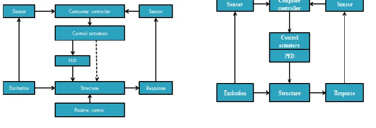
Figure 20 Active control system
Source: B.F. Spencer Jr., G. Yang, J.D. Carlson, and M.K. Sain; Smart Dampers for seismic protection of structures: A full scale study; Proceedings of 2nd world conference on structural control, 1998.
An active structural control system has the basic configuration as shown schematically in (Figure 20). It consists of (a) sensors located about the structure to measure either external excitations, or structural response variables, or both; (b) devices to process the measured information and to compute necessary control force needed based on a given control algorithm; and (c) actuators, usually powered by external sources, to produce the required forces. In comparison with passive control systems, a number of advantages associated with active control systems can be cited; among them are (a) enhanced effectiveness in response control, (b) relative insensitivity to site conditions and ground motion, (c) applicability to multi-hazard mitigation situations, (d) selectivity of control objectives. While this description is conceptually in the domain of familiar optimal control theory used in electrical engineering, mechanical engineering, and aerospace engineering, structural control for civil engineering applications has a number of distinctive features, largely due to implementation issues, that set it apart from the general field of feedback control. In particular, when addressing civil engineering structures, there is considerable uncertainty, including nonlinearity, associated with both physical properties and disturbances such as earthquakes and wind, the scale of the forces involved can be quite large, there are only a limited number of sensors and actuators, the dynamics of the actuators can be quite complex, the actuators are typically very large, and the systems must be fail-safe.
Figure 21 Hybrid control system Figure 22 Semi-active control system
Source: B.F. Spencer Jr., G. Yang, J.D. Carlson, and M.K. Sain; Smart Dampers for seismic protection of structures: A full scale study; Proceedings of 2nd world conference on structural control, 1998.
130 bounded-output stability is guaranteed. Semi-active control devices are often viewed as controllable passive devices. A side benefit of hybrid and semi-active control systems is that, in the case of a power failure, the passive components of the control still offer some degree of protection, unlike a fully active control system.
VII. CONCLUSIONS
Structural response control for seismic resistance outlines to be a better protective system than any other methods of earthquake resistance design. The design and development of these systems to overcome their limitation is still a growing field of research. The need is to develop devices and control systems with less or no external power demand and yet more efficient and performance oriented. The drawbacks of these systems have to be solved to increase their applicability to a wider range of variety of structures.
As the response of structure to external excitation is dependent on the characteristics of the structure, the response is different for different structures; hence a more unique control system applicable to all kinds of structures has to be developed. This development of a unique smart control system demands a better knowledge of the response of structure under any external excitation.
Field experience of recent earthquakes confirms the expectations of engineers for dynamic response behavior and performance of structure under the influence of response control devices. However, there are limitations to the use of these systems and require further investigations. It includes the uncertainty of response in the near field of an active fault, the non-optimal behavior of protective systems for both small and large earthquakes, and a lack of certainty about the ultimate limit states in unexpectedly large events. As a consequence, in some jurisdictions, code provisions for protective systems are more grueling than for conventional construction, which is a strong deterrent to their use. The limited availability of design guidance in text books, code commentaries, and other design aids are further inhibitions to the wider use of these systems.
REFERENCES
[1] A.K. Chopra; A Book on Dynamics of Structure.
[2] S.K. Duggal; A Book on Earthquake resistant design of structure.
[3] Pankaj Aggarwal & Manish Shrikhande; A Book on Earthquake resistant design of structures. [4] Benson H. Tongue; A Book on Principles of vibration.
[5] “Earthquake ground motion and response spectra”; Bijan Mohraz and Fahim Sadek
[6] S.J. Patil and G.R. Reddy; State of art review-Base isolation for structures; International Journal of Emerging Technology and Advance Engineering, Volume 2, Issue 7, July 2012; Page 438-453
[7] Alessandro Martelli; State of the art on the development and application of seismic vibration control techniques and some innovative strengthening methods for civil and industrial structures; 17th International conference on structural mechanics in reactor technology (SMiRT 17); Prague, Czech Republic; 17-22 August 2003; Paper: K13-4.
[8] S.K. Jain and S.K. Thakkar; seismic response of building base isolated with filled rubber bearings under earthquakes of different characteristics; 12th world conference on earthquake enginnering; 2000.
[9] I.G. Buckle; Development and application of Base isolation and Passive energy Dissipation: A world overview; Proceedings of ATC-17, Seminar and workshop on Base isolation and Passive enrgy dissipation; 1986; Page 153-174.
[10]Seismic isolation and protection system, “Passive damping devices for earthquake protection of bridges and buildings; Christian Meinhardt, Daniel Siepe and Peter Nawrotzki”; The journal of ASSIS, vol II 2011 [11]“Seismic damage control with passive energy devices: A case study”; Robert J. McNamara, McNamara/Salvia,
Inc
[12]Juan Enrique Martinez-Rueda; On the evolution of energy dissipation devices for seismic design; Journal of Earthquake Spectra, volume 18, no. 2, May 2002; Page 309-346.
[13]Fahim Sadek, Bijan Mohraz, A.W. Taylor, and R.M. Chung; Passive energy dissipation devices for seismic application; NISTIR 5923, National institute of Standards and Technology, USA; November 1996.
[14]Pocanschi, O. Krause, and B. Haendel; Braced steel frames with Hysteretic Dampers; Proceedings of the 9th European Conference on Earthquake Engineering; 1990; paper-3, page 29-36.
[15]Filiatrault, R. Tremblay, and R. Kar; Performance evaluation of Friction spring seismic damper; ASCE Journal of structural engineering; volume 126, Issue 4, 2000; Page 491-499.
[16]A.S. Pall, C. Marsh, and P. Fazio; friction joints for the seismic control of large panel structures; Precast/Pre-stressed concrete Institute journal; Volume 25, Issue 6, 1980; Page 38-61.
[17]G. Anagnostides, A.C. Hargreaves, and T.A. Wyatt; Development and application of energy absorption devices based on friction; Journal of constructional steel research; Volume 13, Issue 4, 1989; Page 317-336.
[18]B.F. Spencer Jr. , T.T. Soong; new applications and development of active semi-active and hybrid control techniques for seismic and non-seismic vibration in USA; Proceedings of International Post-SMiRT conference seminar on seismic isolation, PED & active control of vibration of structures, Cheju(Korea), 1999;
131 [20]Septimiu George Luca, Florentina Chira and Victor-Octavian Rosca; Passive, Active and Semi-active control
systems in civil engineering; Buletinul Institutului Plitehnic Din Iasi, Constructh Architectura, Tomul LI (LV); April 3, 2005; Page 23-31.
[21]D. Taylor and P. Duflot; Fluid Viscous dampers used for seismic energy dissipation in structures.
[22]H.T. Banks and G.A. Pinter; Damping: Hysteretic damping and models; Invited section, Encyclopaedia of vibration, 2000.
[23]M.L. Lai, P. Lu, D.A. Lunsford, K. Kasai, and K.C. Chang; Viscoelastic Damper: A damper with linear or non-linear material; 11th world conference on earthquake engineering, 1996; Paper no. 795.
[24]B.F. Spencer Jr., G. Yang, J.D. Carlson, and M.K. Sain; Smart Dampers for seismic protection of structures: A full scale study; Proceedings of 2nd world conference on structural control, 1998.
[25]A.K. Panah, and A.H. Khoshay; A new seismic isolation system: sleeved pile with soil rubber mixture; International journal of civil engineering, Volume 13, Issue 2, June 2015; Page 124-132.
[26]X. Chen; Behaviour analysis and application research for treated asphalt-fibre seismic isolation cushion; Proceedings of 13th world conference on earthquake engineering; August 2004; Paper no. 1959.
[27]H. Iemura, and T. Tagnikhany; Optimum design of Resilient sliding isolation system to protect equipments; Proceedings of 13th world conference on earthquake engineering; August 2004; Paper no. 1362.