An Experimental Investigation on tool
Wear & Effect of tool Indentation time on
Tensile Strength of Friction Stir Welded
Joint of Al 6061.
Dilbag Bhardwaj
Assistant Professor, Jagannath University Bahadurgarh
ABSTRACT
This research work contains the effect of tool indentation time on to the weld strength of friction stir welding (FSW). It also includes the investigation on tool wear of FSW tool. Al 6061 is selected as the base plate and it is welded by total five different tool geometry of conventional FSW tool namely cylindrical, cylindrical threaded, tapered, tapered threaded and square pin. For tensile testing of joint ASME-IX is adopted. It has been found that very negligible tool wear has been identified for all tools, minimum tool wear has been found for Square pin tool and 10 second of tool indentation time gives more strength compare to the 5 second of tool indentation time. Tool wear can be decreased by heat treatment of the tool.
Keywords: Al 6061, Friction stir welding, tool indentation time, tool wear.
INTRODUCTION
Friction stir welding (FSW) is a solid-state welding process that gained much attention in research areas as well as manufacturing industry since its introduction in 1991.For almost 20 years; FSW has been used in high technology applications such as aerospace to automotive till high precision application such as micro welding. Friction Stir Welding is a solid-state thermo-mechanical joining process (a combination of extruding and forging) .FSW is a novel green manufacturing technique due to its energy efficiency and environmental friendliness, in this process a cylindrical tool is rotated and transverse along a square butt to milling technique. The frictionally heated material around the tool pin is plastically deformed and extruded to the back of the pin where it formed and forms the weld. The majority of the heat generated from the friction, i.e., about95%, is transferred into the work piece and only 5% flows into the tool. The maximum temperature created by the FSW process ranges from 80 to 90% of the melting temperature of the material being welded FSW offers several advantages over conventional fusion welding process due to its low heat input and absence of melting and solidification process
As shown in Figure 1, forces act in three dimensional spaces. The force along the X-axis, Y-axis, and Z-axis will be referred to as the Translational (Fx), Transverse (Fy), and Axial force
(Fz) respectively, and will be given in Newton’s (N). The Moment (Mz) about the axis of rotation will be referred to as the Torque and given in Newton-meters (N-m).
LITERATURE SURVEY
There are three types of FSW tools, i.e. fixed, adjustable and self-reacting. The fixed probe tool corresponds to a single piece comprising both the shoulder and probe. This tool can only weld a work piece with a constant thickness due to the fixed probe length. If the probe wears significantly or breaks, the whole tool must be replaced. Tool shoulders are designed to frictionally heat the surface regions of the work piece, produce the downward forging action necessary for welding consolidation and constrain the heated metal beneath the bottom shoulder surface. Torque produced during the welding process depends heavily on the contact conditions which are determined by the rotating tool rotational speed, degree of softness of work material or plasticity at the rotating tool to work material interface, axial load exerted and the tool design.
W.Y. Li et al.[1], (2014) studied about The effects of rotational and welding speeds on the microstructure and mechanical properties of bobbin tool Friction stir welded (BT-FSW) Mg AZ31 were investigated. The results indicated that the thermo mechanically affected zone (TMAZ) consisted of equated grains, which were inconsistent with the deformed, rotated and elongated grains found in the TMAZs of bobbin-tool friction stir welded Al alloys and friction stir welded Al and Mg alloys.
S.Yu.Tarasov et al.[2], (2014) studied diffusion wear mechanism in 1.2344 X40CrMoV5-1 steel FSW tool has been carried out from the standpoint of tribological layer generation and interaction with the tool's metal. It is suggested that the fragments of the FSW tool material are deformed and detached from the FSW tool by fracturing along the embrittled grain boundaries under the shear stress developed on the surface of the tool during FSW.
Juan Chen et al. [3], (2015) investigated double-sided friction stirs welding (DFSW) with the combined use of convex and concave tools (concave-DFSW) were studied for the joining of a magnesium alloy. The sound joints made by the concave-DFSW were possible under the appropriate conditions, and the joints had a characteristic structure of the stir zone different from the conventional friction stir welding with a one-sided tool rotation. The mean grain size of the stir zone decreased with the increasing rotation rate of the concave tool. This result indicated that the heat generation during the FSW is not only due to friction but also the plastic deformation. The complicated mixed metal flow that evolved by the convex tool randomized the texture in the stir zone, which provided the preferable tensile behavior.
F.F. Wang et al.[4] (2015) studied the typical microstructure and mechanical properties of joints and the effects of rotational speed on the microstructure and tensile properties are investigated where also investigated. As a result they found that the rotational speed increases, the grain size of the stirred zone increases, whereas the density of strengthening particles decreases; the joint line remnants become compressed remarkably in the shoulder-dominated zone while less changes occur in the probe-shoulder-dominated zone; the softest region shrinks and shifts outward, the average hardness of the stirred zone increases and the hardness profile along the cross section of the joint changes from the U-shaped to W-shaped. The tensile strength of the joint initially increases with rotational speed and then decreases with the maximal strength efficiency reaching 80%; three fracture modes have been observed and cracking initiates at the joint line remnant propagating towards the heat-affected zone, and finally to the border between the thermal-mechanically affected zone and stirred zone.
enable the extensive plastic flow required and minimize the forces acting on the tool. So the traverse speed will be having range of 5 mm/min to 10mm/min .If the material is too cold then voids or other flaws may be present in the stir zone so the time gap is set between the ranges of 30 min to 1 hour.
K.Kumaria et al.[6] (2015) designed a twin-tool setup and fabricated to make a comparative study between twin tool and single tool using double pass in a friction stir welding process. Twin tool helps in generating high heat causing intense plastic deformation in the processed zone. Defect free weld depends not only on the rotational speed, but also on the combined effect of welding speed and rotational speed. Higher hardness profile is observed with higher welding and rotational speeds; defect-free joints are also observed in this combination. Further, SEM results confirm the existence of ductile failure with microscopic voids of different shapes and sizes.
J. Mohammadi et al.[7] (2011) performed lap joint friction stir welding (FSW) between dissimilar AZ31B and Al 6061 alloys sheets was conducted using various welding parameters including tool geometry, rotation and travel speeds. Tapered threaded pin and tapered pin tools were applied to fabricate FSW joints, using different rotation and travel speeds. Various microstructures were observed in the stir zone which can be attributed to using different travel and rotation speeds. Mechanical evaluation including lap shear fracture load test and micro hardness measurements indicated that by simultaneously increasing the tool rotation and travel speeds, the joint tensile strength and ductility reached a maximum value.
Z. Shen et al.[8] (2014) performed Lap welds between Al5754 to DP600 steel (aluminium plate top, and steel plate bottom) were manufactured by friction stir welding (FSW).The effects of welding parameters (i.e. travel speeds and penetration depth into lower steel sheet) on the interfacial bonding, tensile strength, and failure mechanism were investigated. The results show that intermetallic compound of Fe4Al13 was detected at the Al/Fe interface. The weld strength increases significantly by increasing the penetration depth into the lower steel substrate at all travel speeds. The failure mode under overlap shear loadings is premature failure through the aluminium substrate when the penetration depth is more than 0.17 mm, and shear fracture when the penetration depth is less than 0.17 mm.
D. M. Rodrigues et al.[9] (2010) studied the differences in friction stir weld ability, assessed by weld defect analysis and weld strength characterization will be related to the markedly different plastic behaviours of both base materials. Found that high traverse speeds can be achieved in FSW of both base materials with carefully chosen process and tool parameters. These in turn are strongly dependent on the base material characteristics and plate thickness. For cold weld conditions low axial loads led to significant internal and surface defects, whereas for hot weld conditions high axial load values led to tool destruction due to excessive plunge depth in the softened material.
Hasan et al.[10] (2007) developed an artificial neural network (ANN) model for the analysis and simulation of the correlation between the friction stir welding (FSW) parameters of aluminium (Al) plates and mechanical properties. The input parameters of the model consist of weld speed and tool rotation speed (TRS). The outputs of the ANN model include property parameters namely: tensile strength, yield strength, elongation, hardness of weld metal and hardness of heat effected zone (HAZ). Good performance of the ANN model was achieved. The model can be used to calculate mechanical properties of welded Al plates as functions of weld speed and TRS. The combined influence of weld speed and TRS on the mechanical properties of welded Al plates was simulated. A comparison was made between measured and calculated data. The calculated results were in good agreement with measured data.
Lakshminarayanan and Balasubramanian [11] (2008) applied Taguchi approach to determine the most influential control factors which will yield better tensile strength of the joints of friction stir welded RDE-40 aluminium alloy. Through the Taguchi parametric design approach, the optimum levels of process parameters (tool rotational speed, traverse speed and axial force) were determined. The results indicate that the rotational speed, welding speed and axial force are the significant parameters in deciding the tensile strength of the joint.
Sarsilmaz and Çaydaş[12]
EXPERIMENTAL WORK
All the welding has been performed on a vertical milling head situated at Gajanand Engineering 366/5/1 GIDC, Makrpura near hanuman temple, Krishna Steel Street, Baroda, Gujarat.
(a) (b)
Figure 2 Tool-Base plate interaction and welded Plate
Al 6061 is used as a base material and the dimensions of the base plates are 180*150*6 mm and hot work tool steel is used as the tool material. The dimensions of the tools are shown in figure 2. By similar dimensions total 5 types of different tools have been developed namely tapered, tapered threaded, cylindrical, cylindrical threaded and square tool. Interaction between base plate and tool can be seen in figure 3. During the welding two value of tool indentation time is adopted, one 5 second and another 10 second and tool rpm of 2500, 2750 and 3000 is selected while downward force, transverse feed is kept constant. After successful welding of all the plates tensile strength of joints are tested according to the ASME-IX and weight of tool is measured before and after welding so that the tool wear can be identified.
RESULT AND DISCUSSION
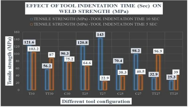
Figure 2 shows the effect of tool indentation time on to the weld strength of FSW joint. It can be seen that tool indentation of 10 second leads to the higher welding strength compare to 5 second
The reason behind that is as the tool stays at a place for more time it generates more heat at that place and there are more chances of taking parent metal in to the plastic stage. If your tool indentation time is very less than it may happen that the material cannot reach to plastic stage and that may lead to failure of tool pin and improper flow of material from retracting side to advancing side and that give improper welding. If your tool indentation time is so high than it may happen that material gets melted and that will lead to improper welding and also that will violate the principle of FSW process.
The tool wear for different tool configuration after the completion of FSW joint. From this figure it is very much clear that there is very negligible loss of material from tool after the FSW process. On comparison it can be seen that square tool has minimum tool wear (gm/1000 mm).
CONCLUSIONS
From this experimental study following points can be concluded:
1. Tool indentation time is very vital parameter which can affect the quality of FSW. Its value should be optimum so that defect free welds can be obtained. Here 10 sec of tool indentation time gives better weld tensile strength.
2. Very small amount of tool wear has been found in all tools. Minimum tool wear has been investigated in square tool geometry and that is 3 gm/1000 mm
REFERENCES
[1] W.Y. Li , T. Fu, L. Hütsch , J. Hilgert , F.F. Wang, J.F. dos Santos , N. Huber.on Effects of tool rotational and welding
speed on microstructure and Mechanical properties of bobbin-tool friction-stir welded Mg AZ31.
[2] S.Yu.Tarasov , V.E.Rubtsov , E.A.Kolubaev On A proposed diffusion-controlled wear mechanism of alloy steel
friction stirs welding (FSW) tools used on an aluminium alloy.
[3] Juan Chen, Rintaro Ueji, Hidetoshi Fujii on Double-sided friction-stir welding of magnesium alloy with concave–
convex tools for texture control.
[4] F.F. Wang, W.Y. Li, J.J. Shen, S.Y. Hu, J.L. Li, J.F. dos Santos, N. Huber on Effect of tool rotational speed on the
microstructure and mechanical properties of bobbin tool friction stir welding of Al-Li alloy
[5] Binxi Chen, Ke Chen, Wei Hao, Zhiyuan Liang, Junshan Yao,Lanting Zhang, Aidang Shan on Friction stirs welding of
small-dimension Al3003 and pure Cu pipes.
[6] K. Kumaria, Surjya K. Pala, Shiv Brat Singh on Friction stirs welding by using counter-rotating twin tool
[7] J. Mohammadi , Y. Behnamian , A. Mostafaei , A.P. Gerlich on Tool geometry, rotation and travel speeds effects on
the properties of Dissimilar magnesium/aluminium friction stir welded lap joints
[8] Z. Shen, Y. Chen, M. Haghshenas , A.P. Gerlich on Role of welding parameters on interfacial bonding in dissimilar
steel/aluminium friction stir welds.
[9] D. M. Rodrigues, C. Leita, R. Louro, H. Gouvei and A. Loureiro on High speed friction stir welding of aluminium
alloys.
[10] Hasan et al., (2007) on artificial neural network (ANN) model for the analysis and simulation of the correlation
between the frictions stir welding (FSW) parameters of aluminium (Al) plates and mechanical properties.
[11] Lakshminarayanan and Balasubramanian (2008) on Taguchi approach to determine the most influential control factors
which will yield better tensile strength of the joints of friction stir welded RDE-40 aluminium alloy.
[12] Sarsilmaz and Çaydaş (2008) a study on full factorial experimental design to study the effect of friction-stir welding