5
A Review of Digital Modulation formats and
OFDM in Optical Communication
Preeti
1, Taruna Sikka
2, Deepak Sharma
31
M. Tech Student, ECE Department, Satpriya Group of Institute, MDU, Rohtak 2
Assistant Professor, ECE Department, Satpriya Group of Institute, MDU, Rohtak 3
Research Scholar, ECE Department, UIET, MDU, Rohtak
ABSTRACT
The increasing demand for high-capacity multimedia services in real-time demands a huge bandwidth for effective and efficient communication. Optical Fiber communication provides a long term solution for this ever increasing traffic demand. Optical communication based upon digital modulation provides greater information capacity, compatibility with multiple digital data services, and also provides higher data security, better quality communication. The main objective of this paper is to give an overview of the digital modulation techniques used in optical communication systems such as amplitude shift keying (ASK), Quadrature phase shift keying (QPSK), binary phase shift keying (BPSK), frequency shift Keying (FSK) .In this paper we have also presented an introduction to Orthogonal Frequency Division Multiplexing
Keywords: Quadrature amplitude modulation (QAM), ASK, QPSK, BPSK, OFDM
I. INTRODUCTION
An Optical Fiber is a thin fiber of glass or plastic that carries light from one end to the other. Optical Fiber is a flexible, transparent fiber made by drawing glass or plastic to a diameter slightly thicker than that of a human hair. Optical fibers are used most often as a means to transmit light between the two ends of the fiber and find wide usage in fiber-optic communications, where they permit transmission over longer distances and at higher bandwidths than wire cables. Fibers are used instead of metal wires because signals travel along them with lesser amount of loss. Fig. 1 given below shows a generic block diagram of a typical optical communication system. It consists of a transmitter, a communication channel, and a receiver, the three elements common to all communication systems
Figure 1: Block diagram of an Optical Communication System.
The optical transmitter is to convert the electrical signal into optical form and to launch the resulting optical signal into the optical fiber. It consists of an optical source, a modulator, and a channel coupler. Semiconductor lasers or light-emitting diodes are used as optical sources. The optical signal is generated by modulating the optical carrier wave.[1]
6 II. DIGITAL MODULATION
Modulation is the process of varying the characteristics of a periodic waveform, called the carrier signal, according to a modulating signal that typically contains information to be transmitted. A modulator is a device that performs modulation. A demodulator performs the inverse of modulation. A modem (from modulator– demodulator) can perform both operations. The next generation wireless communication systems require higher data transmission rates in order to meet the higher demand of quality services. Communicating effectively over a huge distance has always been the challenge for engineers and scientists and with the transition of modulation systems from analog to digital has further complicated the situations.
Digital modulation schemes provide more information carrying capacity, better quality communication, data security and RF spectrum sharing to accommodate more services. The digital modulation schemes are preferred over analog modulation schemes because digital modulation schemes provide larger immunity to noise at the cost of large bandwidth requirements, whereas the requirement of video, audio and data over the computer network or the mobile telephony network termed as the third generation mobile communication poses a serious problem for the bandwidth, so the existing modulation schemes need to be modified for the purpose, where it can handle both the situations of noise and bandwidth efficiency[3][4].
A. Amplitude shift keying (ASK)
Amplitude-shift keying (ASK) is a form of amplitude modulation that represents digital data as variations in the amplitude of a carrier wave. In an ASK system, the binary symbol 1 is represented by transmitting a fixed-amplitude carrier wave and fixed frequency for a bit duration of T seconds.
Figure 2: Modulation signal of ASK
Frequency shift keying (FSK):
Frequency-shift keying (FSK) is a frequency modulation scheme in which digital information is transmitted through discrete frequency changes of a carrier wave. The simplest FSK is binary FSK (BFSK). BFSK uses a pair of discrete frequencies to transmit binary (0s and 1s) information.[5]
Figure 3: Phase change of frequency with binary signal
C. Binary Phase Shift Keying (BPSK)
7 to modulate the pilot subcarriers used for channel estimation and equalization. As we know different channels are used for specific data transmission in cellular systems. The channels used to transmit system related information which are very essential are modulated using BPSK modulation. [6]
Figure 4: BPSK Modulation and Demodulation
Figure 5: Phase change of frequency with binary signal
D: Quadrature Phase Shift Keying (QPSK):
In Quadrature Phase Shift Keying (QPSK) two sinusoids (sin and cosine ) are taken as base functions for modulation. Modulation is achieved by varying the phase of the basic functions depending on the message symbols. In QPSK, modulation is symbol based, where one symbol contains 2 bits.[7]
8 Figure 7: Phase change of QPSK signal with time
E. Quadrature Amplitude Modulation (QAM)
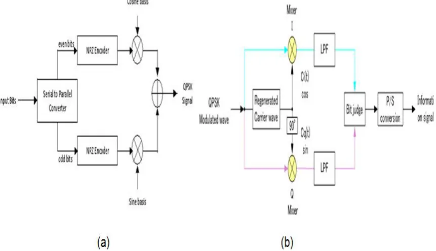
QAM is a form of modulation which is widely used for modulating data signals onto a carrier used for radio communications. It is widely used because it offers advantages over other forms of data modulation such as PSK, although many forms of data modulation operate alongside each other. Quadrature Amplitude Modulation, QAM is a signal in which two carriers shifted in phase by 90 degrees are modulated and the resultant output consists of both amplitude and phase variations. In view of the fact that both amplitude and phase variations are present it may also be considered as a mixture of amplitude and phase modulation.[8]. Figure 8 shows the block diagram of a QAM modulator and demodulator.
Figure 8: Block Diagram of (a) QAM Modulator, (b) QAM Demodulator
The above figure shows the ideal structure of a QAM transmitter, with a carrier center frequency and the frequency response of the transmitter's filter. First the flow of bits to be transmitted is split into two equal parts: this process generates two independent signals to be transmitted. They are encoded separately just like they were in an amplitude-shift keying (ASK) modulator. Then one channel (the one "in phase") is multiplied by a cosine, while the other channel (in "Quadrature") is multiplied by a sine. This way there is a phase of 90° between them. They are simply added one to the other and sent through the real channel. The receiver simply performs the inverse operation of the transmitter. [10][11]
Multiplying by a cosine (or a sine) and by a low-pass filter it is possible to extract the component in phase (or in Quadrature). Then there is only an ASK demodulator and the two flows of data are merged back. In practice, there is an unknown phase delay between the transmitter and receiver that must be compensated by synchronization of the receiver’s local oscillator (i.e. the sine and cosine functions in the above figure). In mobile applications, there will often be an offset in the relative frequency as well, due to the possible presence of a Doppler shift proportional to the relative velocity of the transmitter and receiver. Both the phase and frequency variations introduced by the channel must be compensated by properly tuning the sine and cosine components, which requires a phase reference, and is typically accomplished using a Phase-Locked Loop (PLL).
III. OFDM
9 subcarriers. Two of the fundamental advantages of OFDM are its robustness against channel dispersion and its ease of phase and channel estimation in a time-varying environment. OFDM is now used in most new and emerging broadband wired and wireless communication systems because it is an effective solution to intersymbol interference caused by a dispersive channel. Very recently a number of researchers have shown that OFDM is also a promising technology for optical communications.
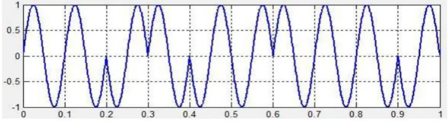
Orthogonality is considered as a property that allows multiple information signals to be transmitted perfectly over a common channel and detected without interference. OFDM achieves Orthogonality in the frequency domain by allocating each of the separate information symbols onto different orthogonal subcarriers. OFDM signals are generated from a sum of sinusoids, with each corresponding to a subcarrier as shown in Figure 9.
Figure 9: Spectrum of Orthogonal OFDM subcarriers
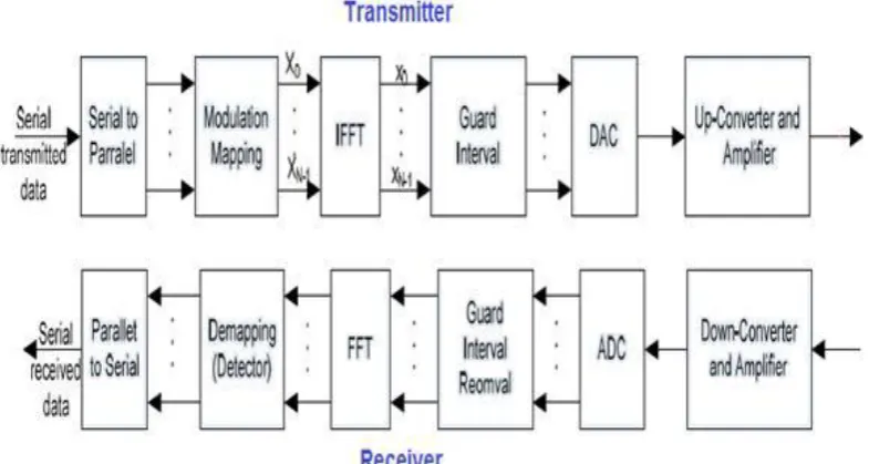
Figure 10 shows the block diagram of transmission system using OFDM. The high rate digital data stream is split into N parallel streams. Each stream is mapped to a symbol stream using some modulation scheme (QAM, PSK, etc). The symbols are modulated onto the subcarriers using the inverse discrete Fourier transform (IDFT). IDFT operation is a transformation of the OFDM. Symbol from the frequency domain to time domain. The inverse fast Fourier transform (IFFT) performs the same operation as an IDFT, except that it is much more computationally efficiency. After the IDFT operation, a cyclic prefix is added to the OFDM symbol prior to digital- to-analogue converter (DAC).
Figure 10: Block Diagram Showing a Basic OFDM System
10 IV. ADVANTAGES and DISADVANTAGES OF OFDM
OFDM has several advantages such as high spectral efficiency; tuned sub-channel receiver filters are not required, low sensitivity to time synchronization errors, Efficient implementation using FFT, can easily adapt to serve channel conditions without complex equalization. Robust against narrow-band co-channel interference and robustness against intersymbol interference and fading caused by multipath propagation. Along with these advantages, OFDM also has certain inherent disadvantages too such as high Peak-to-Average-Power Ratio (PAPR), Sensitive to Frequency Synchronization Problems, Sensitive to Doppler Shift.
CONCLUSION
In this review paper we have presented an overview of various digital modulation techniques such as ASK, QPSK, BPSK, and frequency shift Keying (FSK).we have also presented a brief introduction to next generation optical modulation technique OFDM its advantages and disadvantages. This paper will provide a direction to the researchers to pursue their research in the field of digital modulation based advanced optical networks efficiently and effectively.
REFERENCES
[1] Nikolay karelin et al., “Dual Time Scale Simulation of Dynamics and Reconfiguration of Fiber Optical Networks ”, IEEE, 978-1-4673-2229, April 2012.
[2] Chen et al., “Novel Modulation Scheme Based on Asymmetrically Clipped Optical OFDM for Next Generation Passive Optical Networks”, Optical communication networking, 1943-0620, vol. 5, Aug. 2013.
[3] Vinay Chambola et al., “Performance Analysis of OBS Network Using Fiber Delay Line: A Simulation Approach”, ICCI, Oct. 19-20, Mumbai, India, IEEE 2011.
[4] A. Hodzic, “Investigations of high bit rate optical transmission systems employing a channel data rate of 40 Gb/s”, PhD thesis, Von der Fakult¨at IV - Elektrotechnik und Informatik - der Technischen Universit¨at Berlin zur Erlangung des akademischen Grades, Berlin, Germany,
[5] A.Islam, A.Z.M.Touhidul Islam, Performance of Wi-Max Physical Layer with Variations in Channel Coding and Digital Modulation underRealistic Channel Conditions, IJIST, Vol.2, No. 4, July 2012
[6] S.A.Oyetunji, A.A.Akinninranye, Performance Evaluation of Digital Modulation Techniques in AWGN Communication Channel, IJERT, ISSN:n2278-0181, Vol. 2, Issue 5, May 2013
[7] V.Tilwari, A.S.Kushwah, Performance Analysis of Wi-Max 802.16e Physical Layer using Digital Modulation Techniques and Code Rates ,IJERA, ISSN: 2248-9622, Vol. 3, Issue 4, July-Aug. 2013, pp 1449-1454..
[8] Geetu, H. Singh, M. Singh, Optimization Method for Analysis of Bit Error Rate with BPSK Modulation Technique, IJSER, ISSN: 2229-5518,Vol.3, Issue 6, June 2012.
[9] Ronald Holzlöhner et al., “Accurate Calculation of Eye Diagrams and Bit Error Rates in Optical Transmission Systems Using Linearization”, Journal of Lightwave Technology, Vol. 20, No. 3.
[10] D.K.Sharma, A.Mishra and R.Saxena, Analog and Digital Modulation Techniques : An Overview, TECHNIA-IJCSCT, ISSN 0974-3375,VOL. 3,NO. 1, July 2010.
[11] C. Murthy and M. Guru Swamy, “WDM Optical Networks”, Prentice Hall PTR.
[12] M.Fitton, Principles of Digital Modulation, Telecommunications Research Lab., Toshiba Research Europe Limited [13] http://www2.rad.com/networks/wdm/wdm.htm
[14] K. B. Kumar. and J. M. Jaffe, “Routing to Multiple Destinations in Computer Networks”, IEEE Transactions Commun., Vol.COM-31, no. 3, Pg. 343-351,.
[15] http://www2.rad.com/networks/wdm/wdm.htm.
[16] C. H. Lin and C. H. Wang, “A Hybrid Multicast Scheduling Algorithm for Single Hop WDM Networks”.