INTRODUCTION
Commonly used cable control systems in GA1 aircraft, helicopters and gliders require periodical inspection, after a specific working time (flight hours) or a time interval, e.g. 1 year. During the inspection of cable systems of planes, the follow-ing are examined: cracks in wire of cable, friction wear of cables, fretting, corrosion, cable pulleys and skids abrasive wear, cable elongation, corro-sion, cable socked, joint etc. Wear of cable and extension are nonlinear type of variation [5]. The required values of the cable tension of the cable control systems are determined in the design pro-cesses and calibrated by structural tests, airframe vibrations and flight tests. The subject of the ar-ticle is the analysis of tension measurements of cable control systems based on the three-point bending method, by the strain gauge2 [1]. The
1 General Aviation, Certification Specification for Normal, Utility, Aerobatic and Commuter Aero-planes and gliders in polish are named as light planes. In heavy aircraft (mass above 12 000 lbs), automatic tension adjustment systems are used. 2 strain gauge – adopted in the Polish language, used
in aviation, the name of a cable tension measurement
method is commonly used in determining the ten-sion of ropes, cables, strings, and cable control systems of airplanes. Figure 1 demonstrates a typ-ical cable control system of an airplane. The actu-al vactu-alue of cable tension and their change during operation depends on the pilot/pilots effort, i.e. forces generated on the controls (CS.23.395 [3]) and the forces generated on the rudders surfaces are affected by the stiffness all elements of system control (cables – C1, fittings – C2), stiffness of the airframe structure (C3), and the actual tempera-ture of the airframe units. Additionally, all aircraft operation requirements concerning control cable systems, pulleys, slides and forces must meet requirements3, e.g. [3], including positive load
forces in any flight or ground operating. All forc-es should be in the quasi linear range of stretch-ing the cable Figure 24. Loads of cable systems must additionally meet the requirements of cable manufacturers and other accepted or mandatory
tool borrowed from English (cable tensiometer) 3 in analytical and certification practice, analytical
and empirical evidence of compliance with legal requirements is required
4 Designing the tension of cable airframe control sys-tems is not the subject of this study.
Examination of Aircraft’s Cable Control Systems Tension
Józef Brzęczek
11 Department of Components Manufacturing and Production Organization, Faculty of Mechanics and
Technology, Rzeszow University of Technology, ul. Kwiatkowskiego 4, 37-450 Stalowa Wola, Poland, e-mail: j.brzeczek@prz.edu.pl
ABSTRACT
Cable control systems are widely used in GA aircrafts and gliders. The paper deals with the accuracy of measure-ment pertaining to the tension of cables at the production stage and the maintenance of aeronautical products. Pro-ducers of the measuring instruments used to measure tension do not explicitly define how they should be calibrated and stipulate using special methods and stands. The paper discusses a possible method of tension measurement, measuring tools, methods of calibration and possible errors in the adopted measurement and calibration methods as well. The possible error analysis takes into consideration, the stands construction and details: measuring the instruments system, temperature influence length of reference cable, etc.
Keywords: cable, tension measurement, tensiometer validation, Volume 13, Issue 2, June 2019, pages 65–71
https://doi.org/10.12913/22998624/106238
Research Journal
Accepted: 2019.04.09requirements, including in the fatigue, diameters and construction of cable pulleys, arc of contact, required safety factors, etc.
The operating tensions of the aircraft con-trol cables system are determined in the Aircraft Technical Service Manuals, with the influence of temperature assessment. The requirements are supported by the results of stiffness tests, real exploitation forces, vibration, and flight tests5, including aeroelastic phenomena as well. Simi-lar requirements are used in relation to cable sys-tems with built-in autopilots. The loads control systems additionally includes the loads on the ground, e.g. loads from gusts and so-called bru-tal handling, parking etc. [3]. During operation, there is a change in the tension of cable systems caused by: the use of cables [4, 5] and fitting sys-tems (pulleys, slides, covers, etc. [3, 6]) and their elongation and deflection. The changes in the ten-sion of cable systems e.g. Figure 1, are caused by the variable movements and loads are a normal exploitation phenomenon6.
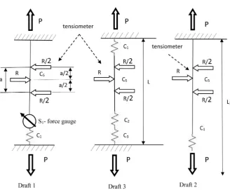
The subject of the presented paper is a dif-ferential method adapted for determining the ten-sion force of airframe control systems with strain gauges operating on the principle of three-point bending of a cable. Typical and service measure-ments are burdened with specific errors. Measure-ment of cable tension with a strain gauge is an indirect measurement method and based on mea-suring the transverse force related to the bending of a tensioned cable.
THE PRINCIPLE OF MEASUREMENT.
In practice of cable tension measuring with a strain gauge, there may be three cases given in Figure 3. (Drafts 1,2,3). Sketch 1, presents a case of cable tension measurement, with a determined reference cable length L, tensioned between rigid elements (deformation of the cable attachment are negligibly small) taking into account only the cable stiffness C1. Sketch 2 presents the case of measurement with one-sided fixing of the cable with its stiffness C1, loaded by a known force.
5 CS 23.689, CS 23.397, CS 23.441, CS 23.455, CS 23.629, CS 23.683 and related AMC and FTG 6 reduction of this effect is reduced by stretching the
lines to a certain value of force prior to installation
on the aircraft. Initial string tension in the subject
literature is called “coaching” or preliminary ten-sion, pre-tensioning and so-called cable training.
Sketch 3 shows the actual case of mea-surement of cable tension with a determined length L1, with rigidity of the system i.e.: C1 ca-ble stiffness, C2 stiffness of control system (with fitting of the pulley and their deformation under actual load of system, fretting, wear and temper-ature) and C3 stiffness of the airframe (1). The actual stiffness and thermal changes affect the measurement results.
𝐶𝐶3= ∑ 𝐶𝐶3,𝑖𝑖 𝑛𝑛
𝑖𝑖=1
(1)
The paper analyzes the used method and de-tails of measuring and errors with the influence of calibration results performed on reference cable lines on the final results of cable tension mea-surement. The presented results may be helpful in the preparation and implementation of struc-tural tests, including the stiffness (susceptibility) examination of cable control systems, accepting or declining the possible spreads of measurement results, including measurement uncertainty and determination [3] – 23,619. The lateral defor-mations of the cable cased the axial force in the cable7. The angle of the cable between the base
a of the measuring tool (Fig. 4) puts force on the support in the middle of the base and transfers the force to the spring of the strain gauge (C4) me-chanically connected with the indicator system.
Used method and the construction of this type of instruments is characterized by errors defined by the formula (2) in accordance with Figure 4:
b∓Δb = f (C_4 (α∓Δα), C_5 (b + Δb)) (2) where: + Δb – the error resulting from the de-pendence (dl, Rd), diameter and type of the cable and the radius of rounding the supports
± Δα – errors of the measuring system
and gauge: systematic (hysteresis, in-dications, mechanical etc.) and random (wrong setting of the device in relation to the cable, wrong support beams, different instrument base)
The afore-mentioned parameters are not di-rectly included in the presented results, but affect the accuracy of the measurement by the struc-ture of the cable: material, the way of winding, 7 In non-aircraft construction solutions, the use of
Fig. 1. Typical cable control system of elevator
Fig. 2. Typical graphs of cable stretching
diameters of wire etc. [6] All of them are included in the coefficient C5 defined in Figure 4.
EXAMINATION OF TENSIOMETERS
Examination of the device was carried out by performing measurements on a referred cable loaded by a known tensioned and then compar-ing with the measurcompar-ing results and introduccompar-ing corrections (systematic error). The devices can by examined on stands with two possible designs (Fig. 3.1 and Fig. 3.2). Both of them exist in prac-tice and introduce errors. First of them is the ef-fect of the lack of real conditions of calibration and measurement: airframe stiffness, rigidity of cable routing systems, cable length (Fig. 3.3). In the case given in Figure 3.2. the stiffness of the structure is omitted. The scheme of the stand pre-sented inFigure 3.1 is convenient and universal for examination but is burdened with the great-est errors caused by the stiffness of fixing the
reference cable and the strong influence of the cable length. Examination of the tensiometers on the stand described in Figure 3.1 is carried out with the following assumptions:
• the loads must be compatible with their per-missible operating load and appropriate to the cable diameter and the measuring range of the examined strain gauge;
• device gauges S1 are used to calibrate the in-struments (Fig. 3.1), with the current verifica-tion certificate (calibraverifica-tion);
• the strain gauge is prepared according to the diameter of the cable.
The stand described on Fig. 3.1 is a universal and the most commonly used, and the paper ana-lyzes the errors for this case. In practice, the stand described in Figure 3.1, due to the overall dimen-sions indicated the cable is threaded through a set of cable pulleys (frictional forces are negligible), and the change in the value of the force is car-ried out by a screw or hydraulic system. Figure 5
Fig. 4. Scheme of measurement of cable system tension with a strain gauge
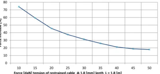
shows the theoretical variation in tension (%) re-alized in accordance with the diagram 3.1 for a steel cable diam. φ 1.8 mm with a length of 1.8 m.
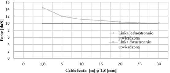
The observed effect of the loads apply by tensiometer on the cable tension value decreases with the increasing tension value of the examined cable Figure 5 and its length increase Figure 6 and Figure 7. as well. With a tension of approx. 5 daN, closing the device depending on the diameter of the cable causes a variation from 70% to 100%, and with a pre-tension of approx. 40 daN. This change is significantly reduced from 13% to 27%, for cable with approx. 280 daN breaking force.
The theoretical analysis of the influence the tensiometer fastening was carried out for cable with diam. of φ 1.8 mm and φ 4.5 mm, with differ-ent lengths based on [3], for the tensiometer with a base a = 85 mm. The calculation model [2,1] of the measuring by tensiometer consists of contact rigid elements and movable supports – accord-ing to Figure 4. The analysis omits the friction between the supports and the cable (the lines are lubricated) and the influence of the support beams depending on the tested cable diameter. The re-sults of the calculations are presented in Figure 6 and Figure 7. They are related to a defined val-ue of the tension of the system without control
forces. The actual value of the cable tension in flight, Figure 1 is variable, according control sur-face and control deflection αh and they are differ-ent in the active and reactive wire.
INFLUENCE OF THE BENDING
DEFLECTION VALUE.
Theoretical analysis [2] of bending cable in-fluence for the system as above for different cable lengths with diam. φ 1.8 and φ 4.5 are presented in Figure 8 and Figure 9.
THE INFLUENCE OF ENVIRONMENT
TEMPERATURE
Aircrafts operate in the environment tem-perature range of +/- 60 0C and under these
conditions they must meet all requirements [3]. The operational exploitation cable tension con-trol systems variation with temperature influ-ence on cable system (steel) for semimono-coque and monosemimono-coque planes constructions and steel cable diameters φ 3.2 mm up to φ 4.5 mm are approx. 35–60 daN. These values are ap-prox. 2% of the breaking force of the cable
Fig. 6. The increase in force from the buttoned strain gauge as a function of the cable length φ 1.8 mm
and approx. 4–8% of the nominal operational forces. The theoretical determination of force variation in cable tension of plane cable con-trol systems is limited due to the lack of infor-mation on the deflection of the control system (Fig.1 and Fig. 3.3) under actual loads. The de-tails regarding the actual plane stiffness and the system’s structure were obtained as the results of stiffness tests at operating loads for differ-ent temperatures. An example of such data is presented in Figure 10 prepared on the basis of the An-28 aircraft’s Technical Service Manual.
Generally, the relationship of forces and temperature are linear or semilinear type. The
nonlinearities relationships should appear more strongly in the cases of more built-up cable sys-tems, e.g. pass by the passenger cabin, tanks, etc. For this reason, more reliable theoretical an-alyzes of the influence of temperature on the ten-sion of the cable control systems will be in the case of simple structures. The numerical analy-sis [2] results of the simple cable control system for the diameter of the cable φ 3.5 mm are from 0.3077 daN/0C to 0.5 daN /0C. The available
Technical Service Manuals of semi-closed and light aircraft, reports semilinear variable tension as function of temperature from 0.25 daN/0C to
0.33 daN /0C.
Fig. 8. Increasing the force in the cable φ 1.8 [mm] as a function of the deflection value of the device
Fig. 9. Increasing the force in the rope φ 4,5 [mm] as a function of the deflection value of the device
CONCLUSIONS
The results of analyses show that attractive and commonly used cable tension measurement of airplanes control systems and indicate the serious errors, up to a level that does not allow reliable measurement. The main errors of the used method are: the method of tensiometers examination should take into account the influ-ence of cable length. The results show that in the instruments and cable systems serving as a standard for examining tensiometers (Fig. 3), their lengths should be comparable to real ones on an aircraft, i.e. around 12–20 m. On the basis of these requirements, we can obtain a final er-ror of cable measurement approx. 5%. The influ-ence of the cable diameter in practice is smaller because of Aviation Rules [3] that do not allow applying cable with the diameters smaller than φ 3.2 mm. The results of the analyses indicate that the tensiometers should be examined on different thicknesses of cables control system. The present-ed results of measurements using this method in the case of short cables (less than 10 m) should be verified in terms of the actual impact of the airframe structure stiffness in the load range con-cerned and development of corrections necessary to mark the tensiometer (Fig. 3.3). Similarly, veri-fication should be conducted while assessing the influence of temperature on the stiffness of the control system. The presented results indicate that in the case of not taking into account the param-eters mentioned above, the measurement errors
may fluctuate at the level of technical acceptabil-ity, i.e. approx. 10%. An important aspect for air-craft designers and Airair-craft Maintenance Instruc-tions preparation is the necessity of clearly defin-ing the conditions for examindefin-ing extensiometers, i.e. determining the length of reference lines and their preparation, i.e. for example pre-tensioning (so-called cable training [6]) with specific values and defining the basis and value of forces used tensiometers. It seems appropriate to collect the stiffness structural and cable system data at the stage of structural tests, and further collect infor-mation on stiffness during flight tests at different ambient temperatures. This approach will reduce the measurement error to about 5–7%.
REFERENCES
1. Operation & service manual for cable tensiometer T-5 series;
2. Reid J.D. Development of Advanced Finite Element Material Models for Cable Barrier Wire Rope.
3. Certification specifications for CS-23 Normal, Performance, Aerobatic and Local transport aircraft, November 14, 2003 and related AMC and FTG. 4. Mroziński S. .Inżynieria i Aparatura Chemiczna, 5,
2010, 91–92.
5. Tytko A. Operation of wire ropes. Silesia Katowice-Warsaw 2003.
![Fig. 8. Increasing the force in the cable φ 1.8 [mm] as a function of the deflection value of the device](https://thumb-us.123doks.com/thumbv2/123dok_us/8805437.1774311/6.595.159.439.634.753/fig-increasing-force-cable-function-deflection-value-device.webp)
