NUMERICAL INVESTIGATIONS ON HEAT TRANSFER AND FLOW
STRUCTURE IN A CIRCULAR TUBE WITH VARIOUS SHAPES OF
WINGLET VORTEX GENERATORS
Amnart Boonloi
aand Withada Jedsadaratanachai
b,*a Department of Mechanical Engineering Technology, College of Industrial Technology, King Mongkut’s University of Technology North Bangkok,
Bangkok 10800, Thailand
b Department of Mechanical Engineering, Faculty of Engineering, King Mongkut’s Institute of Technology Ladkrabang, Bangkok 10520, Thailand
A
BSTRACTThe numerical investigations on flow structure, heat transfer characteristic and thermal performance in a circular tube heat exchanger with various shapes of winglet vortex generators are reported. The rectangular winglet vortex generators (RWVG), delta winglet vortex generators (DWVG) and curve winglet vortex generators (CWVG) are inserted in the middle of the test tube on both downstream and upstream arrangements. The effects of blockage ratios; BR = 0.1 – 0.3, with single pitch ratio (PR = 1) and flow attack angle (α= 30o) on thermal performance are studied for the Reynolds numbers; Re = 100 – 2000. The numerical results are presented in terms of flow and heat transfer patterns; tangential velocity vectors, temperature distributions, local Nusselt number distributions, and compared with the smooth tube. As the results, it is found that the use of the winglets performs higher heat transfer rate, friction factor and thermal performance higher than the smooth tube for all cases. The rise of BR and Re leads to enhance on both the heat transfer rate and friction loss due to the stronger vortex flow. The RWVG provides the highest heat transfer rate and friction loss, while the DWVG gives the reversed result. The downstream arrangement produces higher heat transfer rate than the upstream. In addition, the thermal enhancement factor is found to be maximum at BR = 0.2, Re = 1000, for RWVG with pointing downstream around 2.52.
Keywords: Rectangular winglet; Delta winglet; Curve winglet; Thermal performance; Numerical investigation.
1.
INTRODUCTION
1Winglet is a type of the vortex generator, which always use in the tube or channel heat exchanger to augment the heat transfer rate and thermal performance. The winglet can improve the heat transfer rate and performance by creating the vortex flow, swirling flow and impinging flow in the tube. The difference of the winglet geometry may lead to variations of the flow and heat transfer behavior. It is necessary to understand the mechanism in the heat exchanger that installed with the winglet vortex generators. The understanding of flow and heat transfer profiles is a way to develop the new design of the compact heat exchanger. The investigations on flow and heat transfer in the tube heat exchanger had been reported by many researchers on both numerical and experimental methods.
For examples, Min and Zhang (2014) numerically investigated on flow configuration and mass transfer in a membrane channel with rectangular winglets for the Reynolds number, Re = 400 – 1000. They used the rectangular winglets as longitudinal vortex generators to enhance the heat transfer rate. Gholami et al. (2014) studied the heat transfer improvement in a fin-and-tube heat exchanger with 30o wavy rectangular winglet vortex generators; wavy-up and wavy-down, by using an experimental method for the Reynolds number, Re = 400 – 800. They stated that the wavy rectangular winglet vortex generators can augment heat transfer rate with a moderate pressure loss penalty, especially, wavy-up case. Chokphoemphun et al. (2015) experimentally investigated a tube heat exchanger inserted with 30o winglet vortex generators on heat transfer and pressure loss for turbulent regime, Re = 5300 – 24,000. The effects of pitch ratios and blockage ratios for the winglet vortex generators were reported. They stated that use of the
*
winglet vortex generators gives the Nusselt number around 2.03 – 2.34 times higher than the smooth tube. They also claimed that the tube inserted with the winglet vortex generators performs higher thermal performance than the use of wire coil and twisted tape. Caliskan (2014) studied the heat transfer enhancement with punched triangular vortex generators (PTVGs) and punched rectangular vortex generators (PRVGs) in an AR = 2 rectangular channel. The effects of the flow attack angles; 15o, 45o and 70o with single transverse pitch ratio and blockage ratio were presented for Re = 3288 – 37,817. Caliskan (2014) reported that the
PTVG produces the best heat transfer performance and the augmentation of heat transfer rate is around 23 – 55%. Saha et al. (2014) reported the performance assessment in a plate-fin heat exchanger with winglet type vortex generators. The rectangular winglet pair (RWP) and the delta winglet pair (DWP) with common-flow-up and common-flow-down arrangements were studied. They concluded that the strong secondary flow, which created by vortex generators, helps to a better fluid mixing and enhancing heat transfer rate. They also stated that the RWP gives higher heat transfer rate than the DWP. Wang et al. (2015) presented the use of novel longitudinal vortex generators in a fin-and-tube heat exchanger to improve thermal performance. They combined between rectangular wing and trapezoidal wing as the new type of the vortex generators. They indicated that the use of the new type vortex generators gives the heat transfer rate and pressure loss around 1.8 – 24.2% and 1.3 – 29.1%, respectively, when compared with the base case. Li et al. (2015) numerically investigated the flow structure and heat transfer behavior in a fin-and-tube heat exchanger with longitudinal vortex generators; rectangular and delta winglets. As their results, the rectangular winglet provides higher heat transfer rate than the delta winglet. They concluded that the best thermal performance is found at the flow attack angle of 25o and 45o for the rectangular winglet and delta winglet, respectively. Delac
Frontiers in Heat and Mass Transfer
et al. (2014) numerically studied heat transfer improvement in a fin-and-tube heat exchanger with downstream rectangular winglet vortex generators. The influences of the flow attack angles; 5o, 10o and 20o, for the winglet vortex generators were studied for Re = 350 – 2200. They presented that the high values of flow attack angle and winglet high perform enlarge pressure loss. Hsiao et al. (2014) reported the investigations on flow and heat transfer behaviors a micro-channel heat exchanger with rectangular winglet pairs. They found that the rectangular winglet provides a better fluid mixing by generating longitudinal vortices through the test channel. Zdanski et al. (2015) studied the effects of delta winglet vortex generators on the flow topology and heat transfer rate of air over an in-line tube bank with experimental method. They found that the maximum heat transfer rate is higher than the base case around 30%, while the pressure loss increases around 40%. Lin et al. (2015) numerically investigated a fin-and-tube heat exchanger with curved delta winglet vortex generators (CDWVGs) on flow structure and heat transfer characteristic. They indicated that the CDWVG can reduce the size of wake zone and also produces the secondary flow over the test section. These behaviors help to enhance the heat transfer rate and thermal performance. Aliabadi et al. (2015) studied heat transfer augmentation in a tube heat exchanger with delta winglet vortex generators at various arrangements. They reported the thermal performance in term of performance evaluation criterion or PEC is around 1.41 at Re = 8715. Hatami et al. (2015) presented the new design of heat exchanger to recover exergy from the exhaust of diesel engine by using delta winglet vortex generators. Wang et al. (2015) numerically analyzed the pressure loss and heat transfer improvement in a channel with delta winglets. They claimed that the maximum j-factor and f-factor increase around 24.96% and 17.61%, respectively. Du et al. (2014) presented the heat transfer enhancement in a fin-and-tube heat exchanger with 25o punched delta winglet pairs. They stated that the optimum PEC is around 1.23 when using the 25o punched delta winglet pairs. Zhou and Feng (2014) experimentally investigated the heat transfer augmentation in heat exchanger with plane and curved winglet vortex generators. The influences of the three differences winglet shapes; rectangular, trapezoidal and delta, with and without punching holes were reported. They found that the curved winglet provides higher heat transfer rate and lower friction loss than plane winglet for all shapes on both laminar and turbulent regimes. Gong et al. (2015) studied the heat transfer characteristic in a fin-and-tube heat exchanger with punched curve rectangular vortex generators (CRVGs). They found that the use of CRVG
provides higher heat transfer rate than the plain fin due to secondary flow and small size of wake regime. Lofti et al. (2014a) and Lofti et al. (2014b) numerically investigated in three dimensions on flow structure and heat transfer characteristic for a fin-and-tube heat exchanger with new type vortex generators; rectangular trapezoidal winglet (RTW), angle rectangular winglet (ARW), curved angle rectangular winglet (CARW) and wheeler wishbone (WW). The influences of the flow attack angles; 15o, 30o, 45o, 60o and 75o, were studied. They concluded that the CARW performs the best thermal performance at a small attack angle, while the
RTW gives the optimal thermal performance at a large attack angle. In the current work, the numerical investigation is selected to study the flow configuration, heat transfer characteristics and thermal performance in the circular tube with various shape winglet vortex generators due to the numerical result can describe the mechanism in the test tube. The three types of the winglet; rectangular winglet vortex generators (RWVG), delta winglet vortex generators (DWVG) and curve winglet vortex generators (CWVG) with single pitch spacing ratio (PR = 1) and flow attack angle (α = 30o) are compared on flow structure and heat transfer characteristic for laminar regime, Re = 100 – 2000. The numerical results are presented in forms of tangential velocity vectors, temperature distributions, local Nusselt number distributions and performance evaluations. The empirical correlations on both Nusselt number ratio and friction factor ratio for the circular tube heat exchanger with the RWVG, DWVG and CWVG are also reported.
2.
BOUNDARY CONDITION AND ASSUMPTION
2.1 Boundary condition
The boundary conditions of the circular tube heat exchanger with various winglet vortex generators are as follows:
- Inlet and outlet of the computational domain for the circular tube with winglet vortex generators are set as periodic condition. - The air with 300 K (Pr = 0.7) with a constant mass flow rate is assumed in the flow direction rather than constant pressure drop due to periodic flow conditions.
- The properties of the test fluid are assumed to remain constant at average bulk temperature.
- Impermeable boundary and no–slip wall conditions are implemented over the tube wall as well as the winglet vortex generators. - The constant temperature of the circular tube wall is maintained at 310 K while the winglet and smooth plate are assumed as adiabatic wall conditions.
2.2 Assumption
The numerical model for the fluid flow and heat transfer in the circular tube is developed under the following assumptions:
- Steady three–dimensional fluid flow and heat transfer. - The flow is laminar and incompressible.
- Constant fluid properties.
- Body forces and viscous dissipation are ignored. - Negligible radiation heat transfer.
3.
MATHEMATICAL FOUNDATION
Based on the above assumptions, the flow in circular tube is governed by the continuity, the Navier–Stokes and the energy equations. In the Cartesian tensor system these equations can be written as follows: Continuity equation:
i
0i
u x
(1)
Momentum equation:
i j j i j i j j i x u x u x x p x u u
(2) Energy equation:
i
i j j
u T T
x x x
(3) where, Γ is the thermal diffusivity and is given byPr
(4) Apart from the energy equation discretize by the QUICK scheme,
the governing equations are discretized by the second order upwind (SOU) scheme, decoupling with the SIMPLE algorithm, and solved by using a finite volume approach (Patankar, 1980). The solutions were considered to be converged when the normalized residual values were less than 10−5 for all variables, but less than 10−9 only for the energy equation.
Four parameters of interest in the present work are the Reynolds number, friction factor, Nusselt number and thermal enhancement factor. The Reynolds number is defined as
uD
Re
(5)
The friction factor, f is computed by pressure drop,
p, across the length of the periodic tube, L, as
2 2 1 u D L p f (6) The heat transfer is measured by local Nusselt number which can bek D h Nux x
(7) The average Nusselt number can be obtained by
x
Nu
L
Nu
1
x
(8)
The thermal enhancement factor (TEF) is defined as the ratio of the heat transfer coefficient of an augmented surface, h to that of a smooth surface, h0, at an equal pumping power and given by
130 0 0
0
f f Nu Nu Nu
Nu h
h TEF
pp pp
(9) where Nu0 and f0 stand for Nusselt number and friction factor for the
smooth tube, respectively.
4.
TUBE CONFIGURATION AND COMPUTATIONAL
DOMAIN
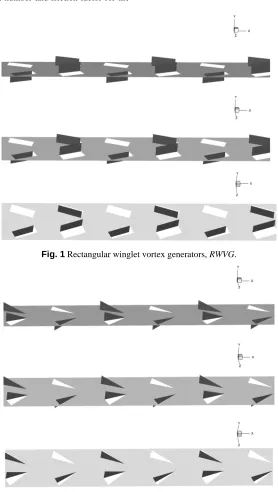
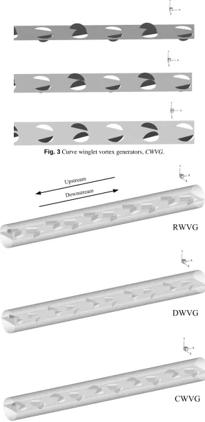
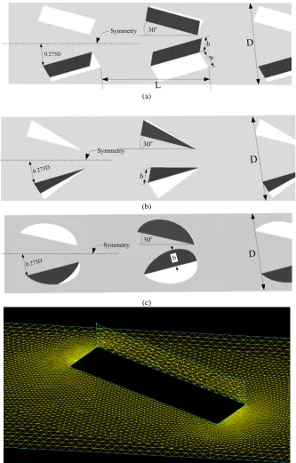
Figs. 1, 2 and 3 present RWVG, DWVG and CWVG, which are punched out from the thin-smooth plates (plate width = D), at BR = 0.2. The tube diameter, D, is equal to 0.05 m. The RWVG, DWVG and CWVG are inserted in the middle of the circular tube on both downstream and upstream arrangements as depicted in the Figs. 4a, b and c, respectively. The influences of the blockage ratios, b/D or BR = 0.1, 0.2 and 0.3 with a single pitch spacing ratio, L/D or PR = 1, and flow attack angle of 30o are investigated numerically in three dimensions for Re = 100 - 2000. The details of winglet parameters are reported as the Figs. 5a, b and c for
RWVG, DWVG and CWVG, respectively. The RWVG with surface mesh is depicted in Fig. 5d.
Fig. 1 Rectangular winglet vortex generators, RWVG.
Fig. 3 Curve winglet vortex generators, CWVG.
(a)
(b)
(c)
Fig. 5 Parameters of the (a) RWVG, (b) DWVG, (c) CWVG and (d) mesh of the RWVG plate.
5.
NUMERICAL RESULTS AND DISCUSSION
5.1 Numerical results
The numerical results are divided into four parts; validation of the computational domain, flow structure, heat transfer characteristic and thermal performance evaluation. The flow and heat transfer profiles may help to describe the mechanism, which occurs in the tube heat exchanger that inserted with various winglets. The understanding on both flow and heat transfer behavior is a way to improve heat transfer rate and thermal performance in the test tube. The performance evaluation is separated into three parts; heat transfer, pressure loss and thermal enhancement factor.
5.1.1 Validation with the smooth tube and grid independence
It must be sure that the computational domain is reliable to predict the flow configuration and heat transfer characteristics, which occurs in the circular tube heat exchanger. The verifications of the domain can be divided into two parts; verification of the smooth tube and grid independence.
Therefore, the current computational domain is reliable to calculate the heat transfer and flow structure in the tube heat exchanger.
The grid independence is tested by comparison four sets of grid cells. The number of grid cells: 120000, 180000, 240000 and 320000, are applied to the computational domain for the circular tube heat exchanger at all types of the winglets: RWVG, DWVG and CWVG at BR
= 0.20, Re = 1000 and downstream. As the numerical results, the increasing grid cells from 180,000 to 240,000 give the Nusselt number and friction factor around ±0.15% and ±0.22%, deviation, respectively. Considering on both times for simulation and accurate results, the 180,000 cells are selected for the current investigation.
5.1.2 Flow structure
The understanding of the flow structure can help to find the ways to improve the heat transfer rate and thermal performance in the heating system.
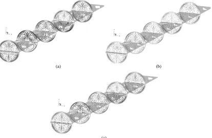
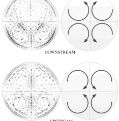
The flow structure is presented in term of tangential velocity in transverse planes at various x/D positions. Figs. 7a, b and c show the tangential velocity vectors in transverse planes for the RWVG, DWVG
and CWVG, respectively, at BR = 0.2 and Re = 1000 of downstream case. As the figures, there are found that all types of the WVG give four main vortex flows through the test section. The symmetry vortex flows are found in the left and right parts due to the symmetry of the winglet geometry. Considering at the upper pair of the vortex flow, the downstream case performs counter-rotating flow with common-flow-up. The RWVG provides the highest density of the velocity vector, while the
DWVG gives the reversed result.
Figs. 8a, b and c illustrate the tangential velocity vectors in transverse planes at various x/D values for the RWVG, DWVG and CWVG
at BR = 0.2, Re = 1000 and upstream case, respectively. The similar flow pattern as downstream is found in upstream case, but the rotational direction is in reverse (see Fig. 10). The counter rotating vortex flow with common-flow-down is found in upstream case when considering at the upper pair of the vortex flow. The CWVG gives the highest density of the tangential velocity vectors, while the DWVG performs the lowest values. The details of the tangential velocity vectors in transverse planes at various x/D values: 0.25, 2.75, 5.25, 7.75 and 10.25, for downstream and upstream are presented in the Figs. 9a and b, respectively. The counter rotating vortex flow and impinging flow on tube wall for both downstream and upstream cases lead to a better fluid mixing between the core of the flow and close to the wall regime. The better fluid mixing and impinging flows are keys for heat transfer augmentation and performance enhancement.
5.1.3 Heat transfer characteristic
The heat transfer characteristics in the tube heat exchanger with various types of winglet vortex generators are presented in forms of temperature distributions in transverse planes and local Nusselt number distributions on the tube wall.
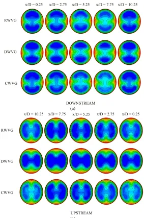
Figs. 11a, b and c present the temperature distributions in transverse planes with various x/D positions for RWVG, DWVG and CWVG, respectively, at BR = 0.2, Re = 1000, downstream case. In general, for the smooth tube with no winglet vortex generators, the blue contour (cold air) is found at the center of the tube, while the red contour (hot air) is found near the wall regime. As the figures, the red layer near the tube wall is thinner when using all types of the winglet vortex generators due to better fluid mixing. The thin red layer is found at the upper and lower parts of the planes, while the left and right parts present in opposite result. Figs. 12a, b and c display the temperature distributions in transverse planes of the tube heat exchanger for RWVG, DWVG and CWVG, respectively, at BR = 0.2, upstream and Re = 1000. The use of the winglet vortex generators leads to better fluid mixing between the core of the tube and wall region for all cases similarly as downstream case. The thin red layer is found in the left and right parts of the planes, while the upper and lower parts show the reversed result.
The details of the temperature distributions in transverse planes for downstream and upstream are shown in the Figs. 13a and b, respectively. There are clearly seen in the figures that the thin red layers are found at the upper-lower parts and left-right parts of the planes for downstream
and upstream, respectively. The reason of this may be that the winglet with pointing downstream can create the flows, which impinge on the upper-lower parts of the tube, while the winglet with pointing upstream generates the flows that impinge on the left-right parts of the tube.
The local Nusselt number distributions on the tube wall that inserted with RWVG, DWVG and CWVG at BR = 0.2, downstream and Re = 1000 are presented in the Figs. 14a, b and c, respectively. In general, the use of the winglet vortex generators can enhance heat transfer rate over the smooth tube with no winglet. The peaks of heat transfer regime are found at the upper and lower parts of the tube for all types of the winglet vortex generators due to the impinging flows. The RWVG performs the highest heat transfer rate, while the CWVG provides higher heat transfer rate than
DWVG. In addition, the lowest heat transfer regimes are found at left and right parts of the tube heat exchanger in all cases.
Figs. 15a, b and c illustrate the local Nusselt number distributions on the tube wall for RWVG, DWVG and CWVG, respectively, at BR = 0.2, upstream and Re = 1000. The peaks of heat transfer regime are done by impinging flows, which are found in the left and right parts of the test tube. The RWVG performs the highest and largest area of heat transfer.
5.1.4 Performance evaluation
Performance evaluations in the tube heat exchanger with various types of the vortex generators are divided into three parts; heat transfer, pressure loss and performance. The heat transfer and pressure loss are reported in terms of the Nusselt number ratio (Nu/Nu0) and the friction factor ratio (f/f0), respectively, while the performance, which computed from both Nu/Nu0 and f/f0, is presented in term of thermal enhancement factor (TEF).
Figs. 16a and b present the variations of the Nu/Nu0 with the Reynolds number at various BRs and winglet types for downstream and upstream, respectively. Generally, the Nu/Nu0 tends to increase with the rise of the Reynolds number and BR for all cases. The RWVG provides the highest heat transfer rate, while the DWVG gives the reversed trend on both downstream and upstream cases. For downstream, the Nusselt number is found to be around 1.5 – 6.2 times, 1.3 – 5 times and 1.3 – 5.5 times higher than the smooth tube for RWVG, DWVG and CWVG, respectively. For upstream, the use of RWVG, DWVG and CWVG gives a higher heat transfer rate over the smooth tube around 1.3 – 5.8 times, 1.3 – 4.8 times and 1.3 – 5.2 times, respectively. The upstream case performs lower Nusselt number than the downstream case due to the weaker vortex flow.
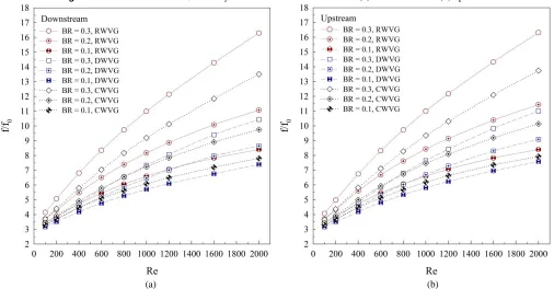
The use of all generators not only enhance heat transfer rate, but also augment pressure loss in the test tube. The variations of the f/f0 with the Reynolds number at various BRs and winglet types are presented in the Figs. 17a and b, respectively, for downstream and upstream. In general, the rise of BR (reduced flow area) and Re results in the increasing friction loss. The highest friction loss is found in case RWVG, while the DWVG
can reduce the pressure loss in the test section. The downstream performs nearly values of f/f0 with upstream case for all types of the winglet. In range studies, the friction factor is around 3.5 – 1.6 times, 3 – 9.5 times and 3 – 13 times higher than the smooth tube, respectively, for RWVG,
DWVG and CWVG.
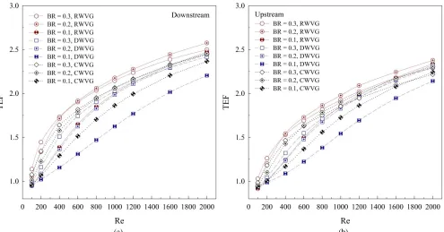
The relations of the TEF with the Reynolds number for the tube with various types of winglet vortex generators are depicted in the Figs. 18a and b, respectively, for downstream and upstream cases. The TEF
increases when increasing the Reynolds number for all cases. Almost cases give the thermal enhancement factor higher than the smooth tube with no winglet (TEF>1). The maximum TEF is found at BR = 0.2, Re = 1000 of RWVG for both downstream and upstream cases around 2.52 and 2.3, respectively. In addition, the BR = 0.1 of DWVG performs the lowest
TEF on both downstream and upstream cases, but it can reduce the pressure loss in the heating system.
The relations between the Nu/Nu0 with BR at various Reynolds numbers and flow directions are shown as the Figs. 19a, b and c for
Figs. 20a, b and c present the relations of the f/f0 with BR at various Reynolds numbers and flow directions for RWVG, DWVG and CWVG, respectively. The highest friction loss is found at BR = 0.3, while the BR
= 0.1 performs the lowest value. The augmentation of the f/f0 is found to be highest in rang 0.2 < BR < 0.3, especially, RWVG. The downstream case performs nearly values of the f/f0 with upstream case for all types of the winglet vortex generators.
Figs. 21a, b and c show the relations of the TEF with BR at various cases for RWVG, DWVG and CWVG, respectively. Almost cases, the peak of the thermal enhancement factor is found at BR = 0.2 due to the
BR = 0.2 gives the optimum ratio between the heat transfer enhancement and friction loss expansion in the test tube.
(a) (b)
Fig. 6 Validation with the smooth tube with no winglet for (a) Nussel number and (b) friction factor.
(a) (b)
(c)
(a) (b)
(c)
Fig. 8 Tangential velocity vectors in transverse planes for the circular tube heat exchanger of (a) RWVG, (b) DWVG and (c) CWVG at BR = 0.2, Re = 1000 and upstream.
(a) (b)
Fig. 9 Details of tangential velocity vectors in transverse planes for (a) downstream and (b) upstream.
5.1.4 Empirical correlation
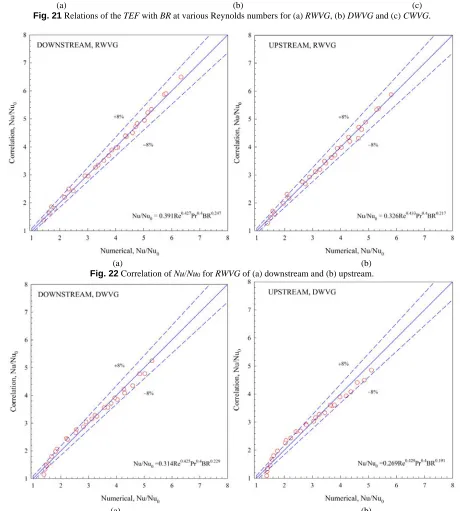
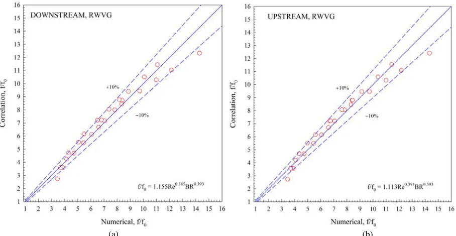
As the numerical results, the empirical correlations for the Nusselt number ratio and friction factor ratio for all cases are reported. The Nusselt number ratio depends on the Reynolds number, Prantdl number and blockage ratio, while the friction factor ratio depends on the Reynolds number and blockage ratio. The values form the correlations are found around ±8% and ±10% deviations for the Nusselt number ratio and friction factor ratio, respectively, as depicted in Figs. 22 – 24 and Figs. 25 – 27. The equations for RWVG, DWVG, CWVG at BR = 0.1 – 0.3, Re = 100 – 2000, α = 30o and PR = 1 are presented in equations 10 – 15 for the Nu/Nu0 and in equations 16 – 21 for the f/f0 as follows;
0.427 0.4 0.247
0
/
0.391Re
Pr
, ,
Nu Nu
BR
RWVG Downstream
(10)0.433 0.4 0.217
0
/
0.326 Re
Pr
, ,
Nu Nu
BR
RWVG Upstream
(11)0.425 0.4 0.229
0
/
0.314 Re
Pr
, ,
Nu Nu
BR
DWVG Downstream
(12)0.429 0.4 0.191
0
/
0.269 Re
Pr
, ,
Nu Nu
BR
DWVG Upstream
(13)0.419 0.4 0.224
0
/
0.360 Re
Pr
,
,
Nu Nu
BR
CWVG Downstream
(14)0.423 0.4 0.193
0
/
0.307 Re
Pr
, ,
Nu Nu
BR
CWVG Upstream
(15)0.385 0.393
0
/
1.155 Re
,
,
f
f
BR
RWVG Downstream
(16)0.391 0.393
0
/
1.113 Re
, ,
f
f
BR
RWVG Upstream
(17)0.342 0.184
0
/
0.843 Re
, ,
f
f
BR
DWVG Downstream
(18)0.359 0.197
0
/
0.787 Re
, ,
f
f
BR
DWVG Upstream
(19)0.366 0.305
0
/
0.998 Re
, ,
f
f
BR
CWVG Downstream
(20)0.377 0.306
0
/
0.944 Re
, ,
f
f
BR
CWVG Upstream
(21)5.2 Conclusion
The numerical studies on flow structure, heat transfer characteristics and thermal performance in the tube heat exchanger inserted with various types of winglet vortex generators; rectangular winglet vortex generators (RWVG), delta winglet vortex generators (DWVG) and curve winglet vortex generators (CWVG) are examined. The influences of the blockage ratios; b/D, BR = 0.1 – 0.3, flow directions; downstream and upstream and Reynolds number; Re = 100 – 2000, are reported. The numerical results are presented in terms of flow structure and heat transfer behavior and compared with the smooth tube. The major findings are as follows:
The use of the winglet vortex generators can improve heat transfer rate in the test tube higher than the smooth tube for all cases. The enhancement of heat transfer rate is due to the vortex flows through the test section and the impinging flow on the tube wall. The vortex flow and impinging flow help to improve the fluid mixing between the main of the vortex flow and near the tube wall regime.
The rise of BR leads to increase heat transfer rates and friction loss for all types of the winglets. The BR = 0.3 performs highest values, while the BR = 0.1 gives the inverted result. This is because the reduction of the flow area effects for enhancing vortex strength or vortex intensity. The strength of the vortex flow is a key for heat transfer enhancement.
The RWVG gives highest heat transfer rate, while the CWVG
provides higher heat transfer rate than the DWVG. The reason of this may be that the RWVG can create the strongest vortex flow through the test section, while the DWVG produces the reversed trend. The RWVG not only gives the highest heat transfer rate, but also provides the highest friction loss.
The downstream case shows a higher heat transfer rate than the upstream case, but performs nearly values of friction loss.
The use of all generators gives higher TEF than the smooth tube (TEF>1). In range investigations, the optimal TEF is around 2.52 at BR
= 0.2, Re = 1000, downstream for RWVG. The enhancements of heat transfer and friction factor are around 1.3 – 6.2 times and 3 – 16 times over the smooth tube, respectively.
(a) (b) (c)
Fig. 11 Temperature distributions in transverse planes for the circular tube heat exchanger of (a) RWVG, (b) DWVG and (c) CWVG at BR = 0.2, Re = 1000 and downstream.
(a) (b) (c)
(a)
(b)
Fig. 13 Details of temperature distributions in transverse planes for (a) downstream and (b) upstream.
(a) (b) (c)
(a) (b) (c)
Fig. 15 Local Nusselt number distributions in transverse planes for the circular tube heat exchanger of (a) RWVG, (b) DWVG and (c) CWVG at BR = 0.2, Re = 1000 and upstream.
(a) (b)
Fig. 16 Variations of the Nu/Nu0 with Reynolds number at various BRs for (a) downstream and (b) upstream.
(a) (b)
(a) (b)
Fig. 18 Variations of the TEF with Reynolds number at various BRs for (a) downstream and (b) upstream.
(a) (b) (c)
Fig. 19 Relations of the Nu/Nu0 with BR at various Reynolds numbers for (a) RWVG, (b) DWVG and (c) CWVG.
(a) (b) (c)
(a) (b) (c)
Fig. 21 Relations of the TEF with BR at various Reynolds numbers for (a) RWVG, (b) DWVG and (c) CWVG.
(a) (b)
Fig. 22 Correlation of Nu/Nu0 for RWVG of (a) downstream and (b) upstream.
(a) (b)
(a) (b)
Fig. 24 Correlation of Nu/Nu0 for CWVG of (a) downstream and (b) upstream.
(a) (b)
(a) (b)
Fig. 26 Correlation of f/f0 for DWVG of (a) downstream and (b) upstream.
(a) (b)
Fig. 27 Correlation of f/f0 for CWVG of (a) downstream and (b) upstream.
Acknowledgement
The funding of this work is supported by King Mongkut’s Institute of Technology Ladkrabang research funds and College of Industrial Technology, King Mongkut’s University of Technology North Bangkok, Bangkok, Thailand. The authors would like to thank Assoc. Prof. Dr. Pongjet Promvonge, KMITL for suggestions.
Nomenclature
b winglet height, m
D diameter of a circular tube, m
f friction factor
GCI grid convergence index
h convective heat transfer coefficient, W m-2 K-1
k thermal conductivity, W m-1 K-1
L spacing between winglet, m
Nu Nusselt number
p static pressure, Pa
Pr Prandtl number
PR Pitch spacing ratio
Re Reynolds number
T temperature, K
ui velocity in xi-direction, m s-1
um mean velocity in channel, m s-1
Greek letter
µ dynamic viscosity, kg s-1m-1
Γ thermal diffusivity
α flow attack angle, degree
TEF thermal enhancement factor, (=(Nu/Nu0)/(f/f0)1/3)
ρ density, kg m-3
Subscript
in inlet
w wall
pp pumping power
REFERENCES
Aliabadi, M.K., Sartipzadeh, O. and Alizadeh, A., 2015, “An Experimental Study on Vortex-generator Insert with Different Arrangements of Delta-winglets,” Energy, 82, 629-639.
http://dx.doi.org/10.1016/j.energy.2015.01.072
Caliskan, S., 2014, “Experimental Investigation of Heat Transfer in a Channel with New Winglet-type Vortex Generators,” International Journal of Heat and Mass Transfer, 78, 604-614.
http://dx.doi.org/10.1016/j.ijheatmasstransfer.2014.07.043
Chokphoemphun, S., Pimsarn, M., Thianpong, C. and Promvonge, P., 2015, “Heat Transfer Augmentation in A Circular Tube with Winglet Vortex Generators,” Chinese Journal of Chemical Engineering, 23(4), 605-614.
http://dx.doi.org/10.1016/j.cjche.2014.04.002
Delač, B., Trp, A. and Lenić, K., 2014, “Numerical Investigation of Heat Transfer Enhancement in A Fin and Tube Heat Exchanger using Vortex Generators,” International Journal of Heat and Mass Transfer, 78, 662-669.
http://dx.doi.org/10.1016/j.ijheatmasstransfer.2014.07.027
Du, X., Feng, L., Li, L., Yang, L. and Yang, Y., 2014, “Heat Transfer Enhancement of Wavy Finned Flat Tube by Punched Longitudinal Vortex Generators,” International Journal of Heat and Mass Transfer, 75, 368-380.
http://dx.doi.org/10.1016/j.ijheatmasstransfer.2014.03.081
Gholami, A.A., Wahid, M.A. and Mohammed, H.A., 2014, “Heat Transfer Enhancement and Pressure Drop for Fin-and-Tube Compact Heat Exchangers with Wavy Rectangular Winglet-type Vortex Generators,” International Communications in Heat and Mass Transfer, 54, 132-140.
http://dx.doi.org/10.1016/j.icheatmasstransfer.2014.02.016
Gong, B., Wang, L.B. and Lin, Z.M., 2015, “Heat Transfer Characteristics of A Circular Tube Bank Fin Heat Exchanger with Fins Punched Curve Rectangular Vortex Generators in The Wake Regions of The Tubes,” Applied Thermal Engineering, 75, 224-238.
http://dx.doi.org/10.1016/j.applthermaleng.2014.09.043
Hatami, M., Ganji, D.D. and Bandpy, M.G., 2015, “Experimental Investigations of Diesel Exhaust Exergy Recovery using Delta Winglet Vortex Generator Heat Exchanger,” International Journal of Thermal Sciences, 93, 52-63.
http://dx.doi.org/10.1016/j.ijthermalsci.2015.02.004
Hsiao, K.Y., Wu, C.Y. and Huang, Y.T., 2014, “Fluid Mixing in A Microchannel with Longitudinal Vortex Generators,” Chemical Engineering Journal, 235, 27-36.
http://dx.doi.org/10.1016/j.cej.2013.09.010
Incropera, F., and Dewitt, P.D., 2006, Introduction to Heat Transfer, 5rd ed., John Wiley & Sons, Hoboken, NJ.
Li, L., Du, X., Zhang, Y., Yang, L. and Yang, Y., 2015, “Numerical Simulation on Flow and Heat transfer of Fin-and-tube Heat Exchanger with Longitudinal Vortex Generators,” International Journal of Thermal Sciences, 92, 85-96.
http://dx.doi.org/10.1016/j.ijthermalsci.2015.01.030
Lin, Z.M., Liu, C.P., Lin, M. and Wang, L.B., 2015, “Numerical Study of Flow and Heat Transfer Enhancement of Circular Tube Bank Fin Heat Exchanger with Curved Delta-winglet Vortex Generators,” Applied Thermal Engineering, 88, 198-210.
http://dx.doi.org/10.1016/j.applthermaleng.2014.11.079
Lotfi, B., Zeng, M., Sundén, B. and Wang, Q., 2014a, “3D Numerical Investigation of Flow and Heat Transfer Characteristics in Smooth Wavy Fin-and-Elliptical Tube Heat Exchangers using New Type Vortex Generators,” Energy, 73, 233-257.
http://dx.doi.org/10.1016/j.energy.2014.06.016
Lotfi, B., Zeng, M., Sundén, B. and Wang, Q., 2014b, “Thermo-hydraulic Characterization of The Smooth Wavy Fin-and-elliptical Tube Heat Exchangers Using New Type Vortex Generators,” Energy Procedia, 61, 2343-2346.
http://dx.doi.org/10.1016/j.egypro.2014.11.1199
Min, J. and Zhang, B., 2014, “Numerical Studies of Convective Mass Transfer Enhancement in A Membrane Channel by Rectangular Winglets,” Chinese Journal of Chemical Engineering, 22(10), 1061-1071.
http://dx.doi.org/10.1016/j.cjche.2014.09.004
Patankar, S.V., 1980, Numerical Heat Transfer and Fluid Flow, McGraw–Hill, New York.
Saha, P., Biswas, G. and Sarkar, S., 2014, “Comparison of Winglet-type Vortex Generators Periodically Deployed in A Plate-fin Heat Exchanger – A synergy based analysis,” International Journal of Heat and Mass Transfer, 74, 292-305.
http://dx.doi.org/10.1016/j.ijheatmasstransfer.2014.03.015
Wang, W., Bao, Y. and Wang, Y., 2015, “Numerical Investigation of A Finned-tube Heat Exchanger with Novel Longitudinal Vortex Generators,” Applied Thermal Engineering, 86, 27-34.
http://dx.doi.org/10.1016/j.applthermaleng.2015.04.041
Wang, Y., He, Y.L., Yang, W.W. and Cheng, Z.D., 2015, “Numerical Analysis of Flow Resistance and Heat Transfer in A Channel with Delta Winglets under Laminar Pulsating Flow,” International Journal of Heat and Mass Transfer, 82, 51-65.
http://dx.doi.org/10.1016/j.ijheatmasstransfer.2014.11.016
Zdanski, P.S.B., Pauli, D. and Dauner, F.A.L., 2015, “Effects of Delta Winglet Vortex Generators on Flow of Air over In-line Tube Bank: A New Empirical Correlation for Heat Transfer Prediction,” International Communications in Heat and Mass Transfer, 67, 89-96.
http://dx.doi.org/10.1016/j.icheatmasstransfer.2015.07.010
Zhou, G. and Feng, Z., 2014, “Experimental Investigations of Heat Transfer Enhancement by Plane and Curved Winglet Type Vortex Generators with Punched Holes,” International Journal of Thermal Sciences, 78, 26-35.