37
Copyright © 2018. IJEMR. All Rights Reserved.
Volume-8, Issue-3, June 2018
International Journal of Engineering and Management Research
Page Number: 37-41
Intelligence Digital Energy Meter
Kundeti Krishnarao1 and Jaddu Jhansi Rani2
1Assistant Professor, Department of Electronics and Electrical Engineering, Vikas Group of Institutions, Andhra Pradesh,
INDIA
2Assistant Professor, Department of Electronics and Communications Engineering, LORDS College, INDIA
1Corresponding Author: [email protected]
ABSTRACT
Here a lot of customs are used electrical energy but not pay the bills in time.so here we avoid this problem by using this project. We can measure the power by each load and take the information through the mobile by using GSM module. After the taking alert from the situation the consumer not respond for emergency alert we can cut –off the supply to the consumer by automatically.
Keywords—Liquid Cristal Display, GSM, LCD, PSU
I.
INTRODUCTION
If any consumer did not pay the bill, the operation needs to go to their houses to disconnect the power supply. These processes are time consuming and difficult to handle. By the system, cut the supply automatically. The use of Arduino (microcontroller) there are many improvements in automating various industrial aspects for reducing manual efforts. Now a day the number of Electricity consumers is increasing in great extent. It became a hard task in handling and minting the power as per the growing requirements.
1.1Circuit Diagram
Fig: 1.1 Circuit diagram of Intelligence digital energy meter
1.2 Block Diagram Explanation 1. Power supply
2. ARUDINO Board3. LCD (Liquid Cristal Display) 4. E.M (Energy meter)
5. Relay
6. C.S (Current sensor)
7. GSM (Global System for mobile communication) 8.Load
1.3 Power supply
• Power supply is connected to the Arduino board
as well as LCD throw the 5v DC adoveter. Power supply is a reference to a source of electrical power. A device or system that supplies electrical or other types of energy to an output load or group of loads is called a power supply unit or PSU. The term is most commonly applied to electrical energy supplies, less often to mechanical ones, and rarely to others.
II.
ARDUINO
• Arduino board pin number 0 to 13 are Digital
pins, are connected to the LCD pin.
• Arduino board pin number GND &Vin are the
input power supply pins.
• Arduino board A0 to A5 pins are analog pins.
• Rx/TXare the LED resister.
• ‘L’ is the indicator of Test LED 13.
• Arduino board pin number 8, 9, 10 are
connected to the GSM.
• ARDUINO board pin number 11 ‘relay 1’ and
12 ‘relay 2’ are connected.
• Arduino board pin number () is connected to the
energy meter.
Arduino interface boards provide the engineers, artists, designers, hobbyists and anyone who tinker with technology with a low-cost, easy-to-use technology to create their creative, interactive objects, useful projects
AN AL OG IN ATMEGA328P-PU1121 Re se t BT N ON ww w.Th eE ng in ee ri ng Pr oj ec ts .c om PD
0/RXDPD1/TXDPD
2/INT0 ~ P D3/IN T1/O C2B PD 4/T 0/XCK ~ P D5/T 1/O C0B ~ P D7/A IN1 PC 5/ADC 5/SCL PC 4/ADC 4/SDA PC 3/ADC 3 PC 2/ADC 2 PC 1/ADC 1 PC 0/ADC 0 RE SET PB 0/IC P1/C LK O ~ P B1/O
C1A~ PB2/OC1B
~ P B3/M OS I/O C2A PD 7/A IN1 PB 4/M
ISOPB5/SCK AREF
01234567 8910111213 A5A4A3A2A1A0
AR D1 ARD UINO UNO D7 14 D6 13 D5 1211D4D3 10987D2D1D0 E 6RW 5RS 4 VSS 1 VDD 2 VEE 3 RE AD ING LCD L M01 6L D2 1N41 48 R1 10K D1 1N41 48 R2
330 330R3
Q2 NP N R4 10K L1 230 V A
C 12VL2
SIM Card SIM 900D S2 -104 1Y-Z 097C CE0980 Po wer BTN ON NEX T ST ATUS TXD RX D www .TheEn gin eer ing Pr ojects. com GS M1 SIM 900 D-GRE EN Q1 NP N IP+
4 IP-5
VIOUT 3 VCC 1 GND 2 U1 CU RREN T SEN SO R 230 V A C S UPP LY RE LAY 2 RL Y-S PNO RE LAY 1 IND ICA TOR S IP+ 4 IP-5 VIOUT 3 VCC 1 GND2
U2 C
38
Copyright © 2018. IJEMR. All Rights Reserved.
etc., A whole new breed of projects can now be built that can be controlled from a computer.
2.1 LCD (Liquid crystal display)
• LCD Pin no 1, 3, 5 & 16 are connected to the
ground.
• LCD Pin number is 2 & 15 are connected to the
VCC (5V DC) supply.
• LCD Pin number 4 &6 are connected to
ARDUNIO Board pin number 2 & 3.
• LCD Pin number 11, 12, 13 & 14 are connected
to ARDUNIO Board pin number 4, 5, 6 & 7.
III.
ENERGY METER
• Energy meter is connected to the relay pin
number 1 & Arduino board pin number () connected.
• Energy meter is a main load indicator device.
“A smart meter is an electronic device that records consumption of electrics energy in intervals of an hours or less and communicates that information at least daily back to the utility for monitoring and billing. … Unlike home energy monitors, smart meters can gather data for reporting.”
3.1 Applications
• House Hold Purposes
• Industries
• Hospitals
3.2Advantages
• Installation is simple.
• Cost of manual maintenance is reduced.
• Monthly bills alert by SMS.
• Automatically easy to connect and disconnect.
• System accuracy is high.
3.3 Power Supply
Power supply is a reference to a source of electrical power. A device or system that supplies electrical or other types of energy to an output load or group of loads is called a power supply unit or PSU. The term is most commonly applied to electrical energy supplies, less often to mechanical ones, and rarely to others.
Fig3.1 Power supply on Arduino
Fig: 3.2 Arduino board
3.4 Hardware specification
• Microcontroller: ATmega328
• Operating Voltage: 5V
• Input Voltage(recommended):7-12V
• Input Voltage (limits): 6-20V
• Digital I/O Pins: 14 (of which 6 provide PWM
output)
• Analog Input Pins: 6
3.5 Arduino board explanation
39
Copyright © 2018. IJEMR. All Rights Reserved.
IV.
LCD (LIQUID CRYSTAL
DISPLAY) SIZES
Even limited to character-based modules, there is still a wide variety of shapes and sizes available. Line lengths of 8, 16,20,24,32 and 40 characters are all standard, in one, two and four-line versions. (as shown in fig 3.6)
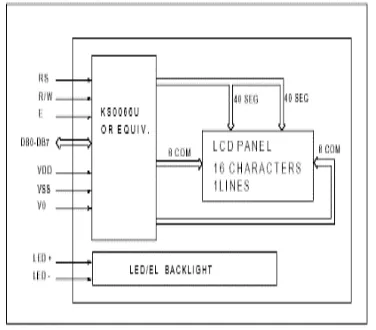
4.1Electrical block diagram
4.1 Electrical block diagram for LCD
4.2 PIN description
Most LCDs with 1 controller has 14 Pins and LCDs with 2 controller has 16 Pins (two pins are extra in both for back-light LED connections). (as shown in fig 3.9)
4.2 Pin diagram of 1*16 lines LCD
4.3 Digital energy meter
4.4 smart energy meter
V.
RELAY
Fig: 5.1 relay
Fig: 5.2Relay construction
5.1 Electrical Current Sensor
40
Copyright © 2018. IJEMR. All Rights Reserved.
The Allegro ACS75x family of current sensors provides economical and precise solutions for current sensing in industrial, automotive, commercial, and communications systems. The device package allows for easy implementation by the customer. Typical applications include motor control, load detection and management, power supplies, and overcurrent fault protection.
Fig: 5.4(a) Operation of sensor
VI.
GSM (GLOBAL SYSTEM FOR
MOBILE COMMUNICATIONS)
GSM (Global System for Mobile
communications) is a cellular network, which means that mobile phones connect to it by searching for cells in the immediate vicinity. GSM networks operate in four different frequency ranges. Most GSM networks operate in the 900 MHz or 1800 MHz bands. Some countries in the Americas use the 850 MHz and 1900 MHz bands because the 900 and 1800 MHz frequency bands were already allocated.
Fig: 6.1 GSM Network
6.1 Our project kit
Fig: 6.2 Project kit of Intelligence digital energy meter
Fig: 6.3 System is normal on condition
Fig: 6.4Load 1 is measure the current in the display
41
Copyright © 2018. IJEMR. All Rights Reserved.
Fig:6.6 Alert message on overload through the mobile
Fig:6.7Automatic cut off power
VII.
CONCLUSION
This research paper demonstrates the concept sand implementation of automatic trip control system for energy management using Arduino controller and GSM. It mainly focused on industrial purpose. The similar idea can be implemented for domestic areas for avoiding the illegal usage of electricity. This paper is aimed at reducing the heavy power and revenue losses that occur due to power theft by the customers. By this design it can be concluded that power theft can be effectively curbed by detecting where the power theft occurs and informing the authorities. Also, an automatic circuit breaker may be integrated to the unit so as to remotely cut off the power supply to the house or consumer who tries to indulge in power theft.
FUTURESCOPE
Though many have tried implementing a country wide AMRS, it is still an unreachable goal, many factors like cost, feasibility and mainly the need to replace the existing system have hindered its
development. At least in near future, the cost involved in the building of this system could be minimized by using more efficient technology implemented worldwide.
REFERENCES
[1] Liang Zhao. (2013). Development of an energy
monitoring system for large public buildings. Elsevier
journal, Energy and Buildings, 66, 41-48.
[2] M. Trejo-Perea, G.J. Ríos Moreno, A. Castañeda- Miranda, D. Vargas-Vázquez, R.V. Carrillo-Serrano, & G. Herrera-Ruiz. (2013). Development of a real time energy monitoring platform user-friendly for buildings.
Elsevier journal Procedia Technology, 7, 238-247.
[3]Abhinandan Jain. (2012, May). Smart and Intelligent
gsm based automatic meter reading system.
International Journal of Engineering Research & Technology,1 (3), 1-6.
[4] Abhinandan Jain. (2012, June). Design and
development of gsm based energy meter. International
Journal of Computer Applications (0975-888), 47(12), 41-45.
[5] S.H. Shete. (2013, January). GSM enabled embedded
system for energy measurement & billing. International
Journal of Scientific & Engineering Research, 4(1), 1-7. [6] www.wikipedia.com.Traditional energy meter systems. Available at:
https://www.google.co.in/search?q=Traditional+Energy+ meter+systems%E2%80%9D&tbm=isch&tbo=u&source
=univ&sa=X&ved=0ahUKEwi494- rpa3bAhULMI8KHf9XB-gQsAQIfQ&biw=1366&bih=662
[7] A. Jain, D. Kumar, & J. Kedia. (2012). Design and
development of gsm based energy meter. International
Journal of Computer applications, 47(12), 41-45. [8] V. V. Dhok & S. S. Deshmukh. (2014). Automatic
energy meter reading system reviews. The International