www.ann-geophys.net/34/357/2016/ doi:10.5194/angeo-34-357-2016
© Author(s) 2016. CC Attribution 3.0 License.
Spatial dimensions of the electron diffusion region in anti-parallel
magnetic reconnection
Takuma Nakamura1, Rumi Nakamura1, and Hiroshi Haseagwa2
1Space Research Institute, Austrian Academy of Sciences, Graz 8042, Austria 2Institute of Space and Astronautical Science, JAXA, Sagamihara, Japan
Correspondence to: Takuma Nakamura ([email protected])
Received: 30 October 2015 – Revised: 3 February 2016 – Accepted: 14 March 2016 – Published: 24 March 2016
Abstract. Spatial dimensions of the detailed structures of the electron diffusion region in anti-parallel magnetic recon-nection were analyzed based on two-dimensional fully ki-netic particle-in-cell simulations. The electron diffusion re-gion in this study is defined as the rere-gion where the posi-tive reconnection electric field is sustained by the electron inertial and non-gyrotropic pressure components. Past ki-netic studies demonstrated that the dimensions of the whole electron diffusion region and the inner non-gyrotropic re-gion are scaled by the electron inertial length de and the width of the electron meandering motion, respectively. In this study, we successfully obtained more precise scalings of the dimensions of these two regions than the previous stud-ies by performing simulations with sufficiently small grid spacing (1/16–1/8de) and a sufficient number of particles (800 particles cell−1 on average) under different conditions changing the ion-to-electron mass ratio, the background den-sity and the electronβe(temperature). The obtained scalings are adequately supported by some theories considering spa-tial variations of field and plasma parameters within the dif-fusion region. In the reconnection inflow direction, the di-mensions of both regions are proportional to de based on the background density. Both dimensions also depend onβe based on the background values, but the dependence in the inner region (∼0.375th power) is larger than the whole re-gion (0.125th power) reflecting the orbits of meandering and accelerated electrons within the inner region. In the outflow direction, almost only the non-gyrotropic component sus-tains the positive reconnection electric field. The dimension of this single-scale diffusion region is proportional to the ion-electron hybrid inertial length (dide)1/2based on the back-ground density and weakly depends on the backback-ground βe with the 0.25th power. These firm scalings allow us to predict
observable dimensions in real space which are indeed in rea-sonable agreement with past in situ spacecraft observations in the Earth’s magnetotail and have important implications for future observations with higher resolutions such as the NASA Magnetospheric Multiscale (MMS) mission.
Keywords. Magnetospheric physics (magnetotail) – space plasma physics (magnetic reconnection; numerical simula-tion studies)
1 Introduction
Magnetic reconnection is one of the most important energy transfer processes in space and laboratory plasmas, which converts magnetic energy to kinetic energy by changing the magnetic field topology (e.g., Birn and Priest, 2007; Yamada et al., 2010; Paschmann et al., 2013; Treumann and Baumjo-hann, 2015). The topology change in the reconnection pro-cess takes place in a small-scale region called the diffusion region where plasmas are decoupled from the magnetic field. The diffusion region in collisionless plasmas is known to have a multi-scale structure based on ion and electron scales, which can be described by the extended Ohm’s law derived from the electron momentum equation (e.g., Kuznetsova et al., 1998; Pritchett, 2001),
E= −1
cUe×B− ∇ ·Pe
en −
me e
dUe
dt (1)
= −1
cUi×B+
J×B/c
en −
∇ ·Pe
en −
me e
dUe dt ,
two-dimensional situation in which reconnection develops in thex–zplane, reconnection is sustained by theycomponent of the electric field Ey and the multi-scale structure of the diffusion region can be described by theycomponent of each term in Eq. (1),
Ey=−(Ui×B)y
| {z }
EVB
y |ion
+(J×B/cen)y
| {z }
EHall
y
| {z }
EVB
y =−(Ue×B)y
(2)
−1 en
∂P exy
∂x +
∂Peyz ∂z
| {z }
ENG
y
−me e
∂U e
∂t +(Ue· ∇)Ue
y
| {z }
EEI
y .
The convection termEyVB|ionis dominant outside the dif-fusion region where electrons and ions move together. In the outer diffusion region where ions are decoupled from elec-trons, the Hall termEHally is not negligible andEyVBis dom-inant. In the inner diffusion region, electron inertial and ki-netic (non-gyrotropic pressure) effects (i.e., EEIy andEyNG) play central roles to dissipate the magnetic energy. In this region,Eyrec=(E+Ue×B)y∼EyNG+EEIy , which is some-times called the reconnection electric field, is dominant. In this paper, the region whereEyrec>0 is defined as the elec-tron diffusion region.
Past numerical studies considering the finite-mass electron fluid showed that the dimension of the whole electron diffu-sion region in the inflow direction (z direction in this paper) is controlled by the electron inertial termEyEIand scaled by the electron inertial lengthde(e.g., Shay et al., 2001). Fully kinetic simulations further demonstrated that near the cen-ter of the diffusion region (the reconnection X-point), EEIy is negligible and instead the non-gyrotropic term EyNG is dominant (e.g., Hesse and Winske, 1998; Pritchett, 2001). This non-gyrotropic pressure component is known to result from the electron meandering motion whose width can be de-scribed by a hybrid of the electron gyroradius and the mag-netic field gradient scale(ρeLB)1/2(e.g., Horiuchi and Sato, 1994; Kuznetsova et al., 1998; Hesse et al., 1999; Dorfman et al., 2008). However, these expressions are not enough to pre-dict precise dimensions of the whole diffusion region and the inner non-gyrotropic region, since the inertial lengthdeand the meandering width can vary within the diffusion region depending on the spatial variations of associated field and plasma parameters. For example, although Shay et al. (2001) obtained the scaling of the dimension of the diffusion region (∝de) by surveying the dependence on the ion-to-electron mass ratio,decan also vary depending on the density varia-tion between the background and the sheet center. The me-andering width can also be affected by the non-uniform
tem-perature due to a local electron acceleration within the inner region.
In this paper, we performed a series of fully kinetic particle-in-cell simulations changing the ion-to-electron mass ratio, the background plasma density and the electron temperature to measure the spatial dimensions of the whole diffusion region and the inner non-gyrotropic region under different conditions. The simulations with sufficiently high resolutions and large number of particles allowed us to ob-tain clear scaling laws of the dimensions of both regions with sufficiently small errors. We here obtained the scalings sepa-rately in the reconnection inflow and outflow directions. The obtained scalings in both directions can successfully be ex-plained by some theories considering the spatial variations of the associated parameters including the electron density and temperature within the diffusion region, indicating the ade-quacy of the scalings. This is the first study that obtains such firm scalings of the dimensions of both regions, which pre-dict precise dimensions in real space and provide important implication to spacecraft observations including the NASA Magnetospheric Multiscale (MMS) mission.
This paper is organized as follows. In Sect. 2, we present the simulation setup employed in this paper. Section 3 con-tains the overview of the simulation results (Sect. 3.1) and the detailed analyses and theories on the scaling in each (in-flow/outflow) direction (Sects. 3.2–3.4). In Sect. 4, we sum-marize the results and discuss the implications for spacecraft observations.
2 Simulation setup
We employ the fully kinetic particle-in-cell (PIC) code VPIC (cf., Bowers et al., 2008). The simulations shown in this paper are 2−1/2 dimensional in the x–z plane. The ini-tial parameters are similar to the ones employed in the Geospace Environmental Modeling (GEM) magnetic recon-nection challenge (Birn et al., 2001; Pritchett, 2001). The initial magnetic field and the corresponding number density profiles are set up asBx(z)=Bx0tanh(z/D0)(Harris sheet) and ni0(z)=ne0(z)=n0sech2(z/D0)+n0∞, where D0 is the half-thickness of the initial current sheet, andn0andn0∞
are the Harris and background density components, respec-tively. D0 is set to be 0.5di0, where di0 is the ion inertial length based onn0.β0=βi0+βe0 based onB0 and n0 is 1.0. The ratio between the electron plasma frequency and the gyrofrequencyωpe/e = 2.0. The system size based ondi0 is fixed asLx×Lz=25.6di0×12.8di0. The boundary con-ditions are periodic along thex direction, with conducting walls along thezdirection. An initial magnetic field pertur-bation is added according toδB=z× ∇ψ, whereψ (x, z)= 0.1 cos(2π x/Lx)cos(π x/Lz).
Table 1. System size,Np/cell,mi/me,Ti0/Te0,βe0and dxnormalized byde0(de∞)andρe0for each run shown in this paper. Run System size (grids) Np/cell ne∞/n0 mi/me Ti0/Te0 βe0 dx/de0(dx/de∞) dx/ρe0 1 1024×512 100 0.2 25 5 0.167 0.125(0.056) 0.433 2 1024×512 800 0.2 25 5 0.167 0.125(0.056) 0.433 3 2048×1024 800 0.2 25 5 0.167 0.063(0.028) 0.217 4 1024×512 800 0.5 25 5 0.167 0.125(0.088) 0.433 5 2048×1024 800 0.2 100 5 0.167 0.125(0.056) 0.433 6 4096×2048 800 0.2 400 5 0.167 0.125(0.056) 0.433 7 2048×1024 800 0.2 25 2 0.333 0.063(0.028) 0.153 8 2048×1024 800 0.2 25 11 0.083 0.063(0.028) 0.306
Figure 1. Time evolution of the reconnection rate (dAy/dt), EyNG and the approximated ENGy1 =
√
2meTexx
e U0ex and ENGy2 =
√
2meTezz e U
0
ez measured at the X-point. The shaded interval in-dicates the quasi-steady phase which is defined as the time when
|dAy/dt|>0.75|dAy/dt|maxwhere|dAy/dt|maxis the maximum value of the reconnection rate.
ratio mi/me, the ion-to-electron temperature ratio Ti0/Te0 andn0∞as listed in Table 1.
3 Results 3.1 Overview
The black solid line in Fig. 1 shows the time evolution of the reconnection rate (dAy/dt) for Run 2. The rate rapidly increases after t=10−i 1 and saturates (reconnec-tion goes to a quasi-steady phase) around t=20−i1. Fig-ure 2a–c shows color contours of the reconnection elec-tric field Eyrec=(E+Ue×B)y, the electron inertial term EyEI=me
e [(Ue· ∇)Ue]yand the non-gyrotropic termE NG y = −1
en e(∂Pexy/∂x+∂Peyz/∂z)for Run 2 (800 particles cell
[image:3.612.334.522.215.579.2]−1) att=20−i 1without any smoothing techniques. Figure 2d shows EyNG att=20−i 1 for Run 1 (100 particles cell−1). The thermal noise due to the PIC methods is generally re-duced by increasing the number of particles per cell. We have confirmed that runs with more than 500 particles cell−1 al-low us to see sufficiently clear structures of Eyrec,EEIy and EyNG (compare Fig. 2c and d). A similar result to Run 2
Figure 2. Color contours of (a–c)Eyrec=(E+Ue×B)y,EyEI= me
e [(Ue· ∇)Ue]y, andEyNG= −en e1 (∂Pexy/∂x+∂Peyz/∂z)att= 20−i1 for Run 2 (800 particles cell−1) and (d) EyNG for Run 1 (100 particles cell−1).
gyrora-Figure 3. Cuts from the white dashed (X=x−xrec=0) and dotted (z=0) lines in Fig. 2c which cross the X-point ofEyNG(red),EEIy (green), EyVB=(−Ue×B)y(blue),Eytot=ENGy +EyEI+EyVB(black solid),Ey(black dashed) andEyVB|ion=(−Ui×B)y(magenta). The plots
are smoothed by averaging the data over |X| ≤1.75de0for (a) and|z| ≤0.25de0for (b). Vertical dotted lines show the locations of the X-point, and vertical dashed lines in (a) and (b) show the locations of|z| =LDfz and|X| =LDfx , respectively.
dius based onB0) would be enough to examine the structure within the electron diffusion region. In this paper, using runs with 800 particles cell−1and similar (or higher) spacial res-olutions (Runs 2–8 in Table 1), we examined the scaling of the spatial dimensions of the electron diffusion region.
Figure 3 shows cuts from the white dashed (X=x−xrec) and dotted (z=0) lines in Fig. 2c of eachEy component, whereXis the shifted coordinate crossing the X-point (x= xrec). Ey is almost constant over the reconnection region with∼0.2VAiB0as seen in past kinetic studies (e.g., Pritch-ett, 2001). This finite Ey is almost perfectly sustained by Eytot=EyNG+EyEI+EyVB. Note again that since the time (t= 20−i 1) shown in Fig. 2 is in a quasi-steady state, me
e ∂Uey
∂t in EyEI can be neglected. At the X-point, Ey is sustained only by EyNG as seen in past kinetic studies (e.g., Pritch-ett, 2001; Ricci et al., 2002; Ishizawa and Horiuchi, 2005; Wang et al., 2015). The positive ENGy region is surrounded by the finite EyEI region. With increasing the distance from the X-point,EVBy increases and reachesEyat the edge of the electron diffusion region (see vertical dashed lines in Fig. 3a and b). Outside the electron diffusion region,EyVB∼Eyand EyEI∼0 andEyNG∼0 in the inflow direction (Fig. 3a), while EyVB> Ey andEyEI<0 andEyNG<0 in the outflow direc-tion (Fig. 3b). Past fully kinetic simuladirec-tions showed that this EyVB> Ey region in the outflow direction extends in larger systems, while the length of the electron diffusion region whereEyVB< Ey(i.e.,Eyrec=EEIy +EyNG>0) is not signif-icantly affected by the system sizes (e.g., Karimabadi et al., 2007; Shay et al., 2007). Note that although the EyVB> Ey andEyrec>0 regions are sometimes categorized as the outer and inner electron diffusion regions, respectively, in this pa-per only theErecy >0 region is defined as the electron diffu-sion region. In the next three subsections, we will analyze the
detailed dimensions of the electron diffusion region where Eyrec>0 and the non-gyrotropic region whereENGy >0. 3.2 Spatial dimension of the electron diffusion region
in thezdirection
Figure 4a showsEyrecandEyNGalong the white dashed line in Fig. 12c for Run 2. In this paper, we defined the dimensions of the electron diffusion region (LDfx andLDfz ) and the non-gyrotropic region (LNGx andLNGz ) as the half-lengths between the edges ofEyrec>0 andENGy >0 regions, respectively (see vertical red lines). Note here that only the|z| =LDfz location is defined as the point whereEyrecfalls down to 0.05Eyrec|max sinceEyrecdecrease asymptotically in thezdirection (almost on the 1/cosh2curve) with some fluctuations which make it difficult to determine the exactEyrec=0 point. We measured these dimensions for all runs and the results are plotted in Figs. 6 and 9, which shows a clear scaling law for each di-mension (less than 3 % of the standard error for each regres-sion line). In this subsection, we discuss the scaling of the dimension of the electron diffusion region in thezdirection (LDfz ). We start here from thezcomponent of the momentum equation of electrons in a steady state atX=0,
∂ ∂z
1
2meUez(z) 2
∼ −1
ne ∂Pezz
∂z −eUey(z)Bx(z). (3) Figure 4b shows the profiles in thezdirection of each term in Eq. (3). The pressure gradient and the Lorentz force are almost balanced (the inertial term can be negligible) within the electron diffusion region. Assuming thatBx(z)varies lin-early (Bx(z)∼B0xz), Eq. (3) can roughly be written as Tezz(0)−Tezz(z)∼eUey(z)
e 2B
0
[image:4.612.107.491.67.215.2]Figure 4. Cuts from the white dashed line in Fig. 2c of Erecy and EyNG (a), ∂z∂ 12meUez(z)2, −1
ne ∂Pezz
∂z and −eUeyBx (b) andne(c) for Run 2, andVth⊥=p(Peyy+Pezz)/2ne(d),Vthz=
√
Pezz/ne (e) andUey (f) normalized byVAe for Runs 2 (red), 5 (green) and 8 (blue). Vertical lines show the location of|z| =LDfz andLNGz for Run 2. The black dotted line in (c) shows the initial density profile.
past kinetic simulations, within the electron diffusion region electrons decoupling from the magnetic field are accelerated by Erecy (e.g., Pritchett, 2001; Hesse, 2011). This produces the finite Uey within the diffusion region whose profile is roughly proportional to the electron Alfvén speed VAe (see Fig. 4f). In addition, it is known that electrons which cross the current sheet in the positive and negative z directions
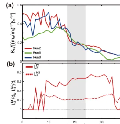
Figure 5. Time evolution of averaged slopes ofBx variations in thezdirection over|z|< LDfz divided by(me/mi)−1/2β
−1/4 e for Runs 2 (red), 5 (green) and 8 (blue) (a), andLDfz andLNGz for Run 2 (b). The shaded interval indicates the quasi-steady phase for Run 2.
(i.e., meandering electrons) produce a double-peak struc-ture of the perpendicular velocity distributionsF (Vey, Vez) at the positive and negativeVezregions (e.g., Ng et al., 2012; Bessho et al., 2014; Shuster et al., 2015). Hence, the shape ofF (Vey, Vez)and the resultingTezz (Vthz) near the center of the diffusion region is controlled by the speed at which electrons cross the current sheet in thezdirection. As seen in Fig. 4e, the increase ofVthznear the center1Vthz(the dif-ference between the peak and background values) is roughly proportional toVAeeven when changingmi/meandβe(i.e., Vth0). From these relations and Eq. (4), we obtained the fol-lowing relation,
B0xLDfz 2
∝Tezz(0)
−Tezz LDfz
eVAe
∝me
e VAe. (5)
As shown in Fig. 5a, the simulation results indicate that B0x is roughly proportional to (me/mi)−1/2β
−1/4 e . Thus, from Eq. (5),LDfz would roughly be proportional toLDfz ∝ (me/mi)1/2βe1/8di=βe1/8de.
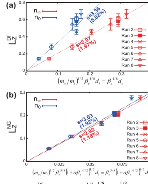
[image:5.612.48.287.66.507.2]is basically controlled by the density of background plasmas which flow into and fill the diffusion region (see Fig. 4c). The slope of the regression line in Fig. 6a for n∞ is 2.07 with
1.97 % of the standard error. From these results, the dimen-sion of the electron diffudimen-sion region in thezdirection would roughly be written as
LDfz ∼2β
1 8
ede∼2 m
e mi
12 β
1 8
edi, (6)
wheren=n∞,B=B0, andTi,e=Ti0,e0are used to obtain βe anddi,e. This scaling is consistent with the past kinetic simulations which suggested the thickness of the electron dif-fusion region is determined by the electron inertial lengthde whenβeis fixed (e.g., Shay et al., 2001; Zeiler et al., 2002; Dorfman et al., 2008).
In addition, when1Vth(∝VAe)is sufficiently larger than Vth0(i.e.,βeis sufficiently low),Vthznear the X-point would roughly be proportional toVAe, as seen in Fig. 4e. In such a lowβesituation, from Eq. (5),B0xLDfz
2
∝meVthz/e. Since the fluxUezBxreachesEynear|z| =LDfz , assuming the lin-earity,U0ezB0xLDfz
2
∼Ey. Thus,Eycan roughly be propor-tional to Ey∝meeVthzU0ez∼
√
meTezz e U
0ez. This expression
is consistent with past theories of Ey component produced by the non-gyrotropic effects near the X-point (EyNG) (e.g., Kuznetsova et al., 1998; Hesse et al., 1999; Dorfman et al., 2008; Divin et al., 2012), in which they derived
EyNG|theory∼ √
2meTezz
e U
0
ez∼ √
2meTexx
e U
0
ex. (7) Dashed and dotted lines in Fig. 1 showENGy ,
√
2meTexx e U
0
ex and
√
2meTezz e U
0
ez at the X-point, respectively. The result indeed shows that Eq. (7) is almost true (that is, EyNG∼ EyNG|theory).
3.3 Spatial dimension of the non-gyrotropic region in thezdirection
The dimension of the non-gyrotropic region in the z di-rection LNGz is believed to be determined by the width of the meandering motion near the X-point (e.g., Kuznetsova et al., 1998; Hesse et al., 1999). The meandering width is known to be described by the z coordinate where the lo-cal gyroradius of electrons exceeds thezcoordinate (that is, ρe(z) > z) (e.g., Biskamp and Schindler, 1971; Horiuchi and Sato, 1994; Kuznetsova et al., 1998). Assuming that Bx(z) varies linearly and the perpendicular thermal velocityVth⊥is
[image:6.612.309.548.68.365.2]constant near the meandering region, thezcoordinate at the edge of the meandering region (z=LNGz ) can be described as ρe(z)∼ρeLBz/z∼z, where ρe=meVth⊥/(eB0) andLBz = B0/B0xis the magnetic field gradient scale. Thus, the mean-dering width that corresponds to the dimension of the non-gyrotropic region can be described asLNGz ∼(ρeLBz)1/2. As
Figure 6. LDfz versus (me/mi)1/2βe1/8di=βe1/8de (a), and LNGz versus(me/mi)1/2βe3/8
q
1+αβ−
1 2
e di=βe3/8
q
1+αβ−
1 2
e de whereα=0.15 (b) normalized by di0 for Runs 2–8. n∞ (red),
andn0 (blue) are examined to calculatedeand di. Each value is the averaged one during a quasi-steady period where|dAy/dt|> 0.75|dAy/dt|max. Error bars show the standard deviation, and the dashed lines indicates the regression lines with slopes and standard errors.
seen in Fig. 4d,Vth⊥is enhanced within the diffusion region
and roughly constant within the meandering region. The in-crease ofVth⊥ from the background region is roughly
pro-portional toVAe(i.e.,Vth⊥∼Vth0+αVAe) even when chang-ingmi/me andβe. From Fig. 4d, the acceleration rateαis roughly 0.15 for all runs.
Since LBz ∝(me/mi)1/2βe1/4 as shown in Fig. 5a, LNGz would be proportional to
LNGz ∝ m
e mi
12 β
3 8
e q
1+αβ−
1 2
e di=β
3 8
e q
1+αβ−
1 2
e de. (8)
As shown in Fig. 6b which shows the averagedLNGz dur-ing a quasi-steady phase for Runs 2–8, this prediction of the scaling well matches the simulation results especially when taking the background densityn∞forβeanddi,e. The slope of the regression lines in Fig. 6b forn∞is 2.92 with 1.18 %
Figure 7. Cuts from the white dotted line in Fig. 2c ofEyrec(a) and EyNG(b) for Runs 2 (red), 5 (green) and 8 (blue), andmeUex∂Uex
∂x ,
−1
ne ∂Pexx
∂x andeUeyBz for Run 2 (c). Vertical lines in Fig. 7a–c show the location of|X| =LDfx ∼LNGx for Run 2.
written as LNGz ∼3β
3 8
e q
1+αβ−
1 2
e de (9)
∼3 m
e mi
12 β
3 8
e q
1+αβ−
1 2
e di,
wheren=n∞,B=B0, andTi,e=Ti0,e0are used to obtain βeanddi,e.
3.4 Spatial dimensions in thexdirection
[image:7.612.327.525.66.274.2]As seen in Fig. 3b,EyEIis basically negative on thexaxis, and the negativeEyEIpeaks are seen outside the positiveENGy re-gion. Hence, the positiveEyrecregion in thexdirection almost corresponds to the positiveEyNGregion (i.e.,LDfx ∼LNGx ) as seen in Fig. 7a and b (see vertical lines for Run 2). In this subsection, we discuss the dimension LDfx (∼LNGx ) of the Eyrec>0 region in thex direction. Figure 7c shows the pro-files along thexaxis (i.e.,z=0) of each term of thex com-ponent of the momentum equation, meUex∂U∂xex, −n1e∂P∂xexx andeUeyBzfor Run 2. In contrast to the profiles in thez di-rection, the inertial term cannot be negligible and therefore the same approach to derive the scaling as shown in Sect. 3.2 cannot be applied toLDfx . Instead, we start here from the ap-proximatedEyNGdescribed in Eq. (7), which is almost equal to the constantEyvalue within the diffusion region as shown in Sect. 3.2. Assuming the linearity in thexdirection and the flux conservation at the edge of the electron diffusion region
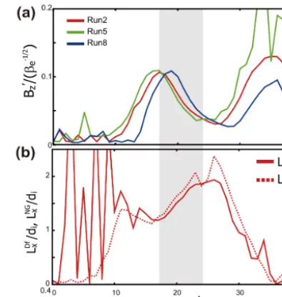
[image:7.612.51.285.66.293.2]Figure 8. Time evolution of averaged slopes ofBz variations in thezdirection over|X|< LDfx divided byβe−1/2for Runs 2 (red), 5 (green) and 8 (blue) (a), andLDfx andLNGx for Run 2 (b). The shaded interval indicates the quasi-steady phase for Run 2.
Figure 9.LDfx (∼LNGx ) versus(me/mi)1/4βe1/4dinormalized by di0for Runs 2–8.n∞(red), andn0(blue) are examined to calculate de anddi. Each value is the averaged one during a quasi-steady period. Error bars show the standard deviation, and the dashed lines indicates the regression lines with slopes and standard errors.
(i.e.,U0exB0zLDfx 2
∼Ey), from Eq. (7),LDfx can roughly be written as
LDfx ∼ 1
B0
z √
2meTexx e
12
∼
me mi
14 B0 B0
zdi 12
β
1 2
edi. (10)
As shown in Fig. 8a, the simulation results indicate that B0z is roughly proportional to β
−1/2
[image:7.612.310.549.347.485.2]sim-ulation results especially when taking the background den-sityn∞ for βe anddi,e. The slope of the regression line in Fig. 9 forn∞is 3.31 with 2.94 % of the standard error. From
these results, the dimension of the electron diffusion region in thexdirection would roughly be written as
LDfx ∼LNGx ∼3β
1 4
e(dide)
1
2, (11)
wheren=n∞,B=B0, andTi,e=Ti0,e0are used to obtain βe anddi,e. Similar scalings were also seen in past kinetic simulations (Hesse et al., 1999; Ricci et al., 2002; Daughton et al., 2006; Karimabadi et al., 2007; Divin et al., 2012), where they indicated that the dimension of the electron dif-fusion region in thexdirection is proportional to(me/mi)1/4 whenβeis fixed.
The same scaling of LDfx can also be derived from the flux conservation at both edges of the electron diffusion re-gion in the inflow and outflow directionsUeinBin∼UeoutBout where Uein=Uez(LDfz ), Ueout=Uex(LDfx ), Bin=Bz(LDfz ), and Bout=Bz(LDfx ). Assuming the linearity and the in-compressibility (which lead to Uein/LDfz ∼Ueout/LDfx ), the above flux conservation can be rewritten as Bin/Bout∼ LDfx /LDfz . From this relation and the scalings used in Sect. 3.2 and this section (B0x (∼Bin/LDfz ), B0z (∼Bout/LDfx ) and LDfz ), we can obtain the relation shown in Eq. (11)LDfx ∝ (me/mi)1/4βe1/4di. This is not surprising since the theoretical Ey at the X-point (Eq. 7) is basically the same value as the flux (UeinBin) at the edge of the electron diffusion region as shown in Sect. 3.2.
4 Summary and discussions
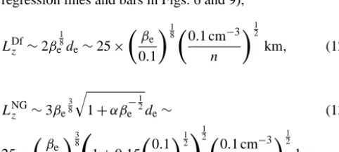
In this paper, based on 2-D fully kinetic PIC simulations we systematically analyzed the dimensions of the whole electron diffusion region of anti-parallel reconnection (LDfx andLDfz ) and the non-gyrotropy dominant region located near the cen-ter of the diffusion region (LNGx andLNGz ). The simulations with sufficiently small grid spacing and large number of par-ticles allowed us to successfully obtain the following precise scalings of the dimensions with sufficiently small errors (see regression lines and bars in Figs. 6 and 9),
LDfz ∼2β
1 8
ede∼25×
βe 0.1
180 .1 cm−3
n 12
km, (12)
LNGz ∼3βe
3 8
q
1+αβ−
1 2
e de∼ (13)
25×
βe 0.1
38
1+0.15 0
.1 βe
12!
1 2
0.1 cm−3 n
12
km,
LDfx ∼LNGx ∼3β
1 4
e(dide)
1
2 ∼ (14)
200×
βe 0.1
140 .1 cm−3
n 12
km,
where we takemi/me=1836 to estimate the real values. The density andβe for all dimensions are taken as the values in the background region. The results show that the dimensions in the inflow direction are basically proportional to the elec-tron inertial length, while those in the outflow direction are proportional to the ion-electron hybrid inertial length. The dependence onβe (the electron temperature) is different for each dimension. As shown in Sects. 3.2–3.4, these scalings are in good agreement with theories that we extended to pre-dict the scalings by considering the spatial variations of field and plasma parameters within the diffusion region. In the the-ories, the above scaling laws can be predicted by inputting the gradients of the magnetic field in the inflow (B0x) and outflow (B0z) directions within the diffusion region which are obtained from the simulations – i.e., the scalings are de-termined self-consistently when the magnetic field gradients are given. Shay et al. (2007) showed that even when con-sidering larger system sizes both the reconnection rate and the gradient in the outflow directionB0znear the X-point are not significantly changed. This could be the reason why the length of the electron diffusion region in the outflow direc-tion whereEyVB< Ey(LDfx in this paper) is not significantly affected by the system sizes, despite the outer region where EyVB> Ey can be extended depending on the system sizes (e.g., Karimabadi et al., 2007; Shay et al., 2007).
the peak-to-peak distance of the electron outflows is roughly two times larger than 2LDfx (see the peak-to-peak distance of blue line in Fig. 3b), the expected peak-to-peak duration when 0.01< n∞<0.1 is roughly 10 s< 1t <1 min, which
is roughly consistent with the observations.
Although the above observation duration of the electron diffusion region predicted from our simulations (1tx=5– 30 s) is calculated under the assumption that the spacecraft is fixed near the center of the plasma sheet (i.e., the X-line motion speed in thezdirectionUrzis small enough), the ob-servation duration would also be sensitive to Urz. We here introduce τ which is defined as the ratio of the observation durations between thezandxdirections,
τ =1tz 1tx
= 2L Df z /Urz 2LDf
x /Urx
(15)
=L Df z LDf
x Urx Urz
∼2 3βe
−18 m
e mi
14U rx Urz
∼0.13× β
e 0.1
−18U rx Urz .
Whenτ >1 the observed data reflect the change of the struc-ture of the electron diffusion region in thex direction rather than that in thezdirection, and vice versa. From Eq. (15), the thresholdτ=1 corresponds toUrz/Urx∼0.1 whenβe∼ 0.1. Although it is difficult to know Urz/Urx in the above Geotail events, the consistency with the predicted duration in the x direction impliesτ >1 (i.e.,Urz/Urx<0.1) in these events.
On the other hand, to analyze the structure of the elec-tron diffusion region in the z direction, the condition with τ <1 (i.e.,Urz/Urx>0.1) would be required. The statistical study of the X-line motion using Cluster (Alexandrova et al., 2015), which analyzed reconnection events following current sheet crossings, showed that the X-line tends to move in the north–south (∼z) direction correlated with the motion of the current sheet, and its motion speed is about 30 km s−1 on average and varies up to 100–200 km s−1(corresponding to 1tz=0.2–5 s when 0.01< n∞<0.1 and βe∼0.1). Since the averaged speed in the x direction in Alexandrova et al. (2015) is 70 km s−1, these X-line motion speeds indicate that the case withτ <1 (Urz/Urx>0.1) would not be uncommon at least for reconnection events with current sheet crossings. Since the expected observation duration of the electron diffu-sion region for such events (0.2–5 s) is comparable to or less than typical spin periods (i.e., the time resolution) of space-craft such as Geotail, Cluster or THEMIS, the detailed struc-ture of the electron diffusion region is expected to be realized for the first time by further comparison with the MMS mis-sion which measures particles with millisecond resolution.
Although this paper treated an anti-parallel magnetic field configuration, effects of the guide magnetic field component, which often exists for the dayside reconnection (e.g., Swis-dak et al., 2003; Hesse, 2006) or the vortex-induced recon-nection (e.g., Nakamura et al., 2013) at the Earth’s magne-topause, should be examined to more generally understand the structure of the electron diffusion region. Since electrons
are more strongly magnetized even near the X-point when considering the guide field, the orbit of electrons near the X-point and the associated structure of the non-gyrotropic re-gion would significantly be affected by the guide field as in-dicated in past kinetic studies (e.g., Horiuchi and Sato, 1997; Ricci et al., 2004; Swisdak et al., 2005; Hesse, 2006). In addi-tion, the strongly magnetized electrons in the guide field case would easily be trapped around the ion and electron diffusion regions (e.g., Egedal et al., 2008), and these trapped electrons would affect the structures and the dimensions of the diffu-sion regions. Considering such guide field effects would be an important future research topic.
Non-steady features, which are also neglected in this pa-per, should also be considered to understand the electron-scale physics of magnetic reconnection. Recent 2-D and 3-D kinetic simulations demonstrated that repeated formation of secondary small-scale flux ropes near the X-line and within the reconnection exhausts drastically disturb steady recon-nection features (e.g., Daughton et al., 2006; Fujimoto and Sydora, 2012; Lapenta et al., 2015). Furthermore, recent 3-D fully kinetic simulations also demonstrated that when con-sidering the strong guide field component, similar turbulent features easily spread even outside these regions and fill the whole reconnection layer through the copious formation of oblique secondary flux ropes (Daughton et al., 2011, 2014). Spacecraft observations using Cluster indeed indicated the existence of turbulence near the X-line in the magnetotail (Eastwood et al., 2009). Understanding the structure of the diffusion region in such non-steady situations would also be an important future research topic.
Acknowledgements. This work is supported by Austrian Science Fund (FWF): P23862-N16, I2016-N20. Simulations were per-formed with resources from the LANL institutional computing pro-gram. The large-scale simulation data in this study are available upon request from the authors. We would like to acknowledge use-ful discussions with W. Baumjohann, W. Daughton, I. Shinohara and S. Zenitani.
The topical editor, C. Owen, thanks two anonymous referees for help in evaluating this paper.
References
Alexandrova, A., Nakamura, R., Semenov, V. S., and Naka-mura, T. K. M.: Motion of reconnection region in the Earth’s magnetotail, Geophys. Res. Lett., 42, 4685–4693, doi:10.1002/2015GL064421, 2015.
Baker, D. N., Peterson, W. K., Eriksson, S., Li, X., Blake, J. B., Burch, J. L., Daly, P. W., Dunlop, M. W., Korth, A., Donovan, E., Friedel, R., Fritz, T. A., Frey, H. U., Mende, S. B., Roeder, J., and Singer, H. J.: Timing of magnetic reconnection initiation during a global magnetospheric substorm onset, Geophys. Res. Lett., 29, 2190, doi:10.1029/2002GL015539, 2002.
reconnectoon: Physics behond the fine structures, Geophys. Res. Lett., 41, 8688, doi:10.1002/2014GL062034, 2014.
Birn, J., Drake, J. F., Shay, M. A., Rogers, B. N., Denton, R. E., Hesse, M., Kuznetsova, M., Ma, Z. W., Bhattacharjee, A., Otto, A., and Pritchett, P. L.: Geospace Environmental Model-ing (GEM) Magnetic Reconnection Challenge, J. Geophys. Res., 106, 3715–3719, doi:10.1029/1999JA900449, 2001.
Birn, J. and Priest, E. R.: Reconnection of Magnetic Fields : Mag-netohydrodynamics and Collisionless Theory and Observations, Cambridge University Press, Cambridge, UK, 2007.
Biskamp, D. and Schindler, K.: Instability of two-dimensional col-lisionless plasmas with neutral points, Plasma Phys., 13, 1013, doi:10.1088/0032-1028/13/11/003, 1971.
Bowers, K. J., Albright, B. J., Yin, L., Bergen, B., and Kwan, T. J. T.: Ultrahigh performance three-dimensional electromag-netic relativistic kielectromag-netic plasma simulation, Phys. Plasmas, 15, 055703, doi:10.1063/1.2840133, 2008.
Daughton, W., Scudder, J., and Karimabadi, H.: Fully kinetic sim-ulations of undriven magnetic reconnection with open boundary conditions, Phys. Plasmas, 13, 072101, doi:10.1063/1.2218817, 2006.
Daughton, W., Roytershteyn, V., Karimabadi, H., Yin, L., Albright, B. J., Bergen, B., and Bowers, K. J.: Role of electron physics in the development of turbulent magnetic reconnection in collision-less plasmas, Nature Phys., 7, 539–542, doi:10.1038/nphys1965, 2011.
Daughton, W., Nakamura, T. K. M., Karimabadi, H., Roytershteyn, V., and Loring, B.: Computing the reconnection rate in turbu-lent kinetic layers by using electron mixing to identify topology, Phys. Plasmas, 21, 252307, doi:10.1063/1.4875730, 2014. Divin, A., Lapenta, G., Markidis, S., Semenov, V. S., Erkaev, N. V.,
Korovinskiy, D. B., and Biernat, H. K.: Scaling of the inner elec-tron diffusion region in collisionless magnetic reconnection, J. Geophys. Res., 117, A06217, doi:10.1029/2011JA017464, 2012. Dorfman, S., Daughton, W., Roytershteyn, V., Ji, H., Ren, Y., and Yamada, M.: Two-dimensional fully kinetic simulations of driven magnetic reconnection with boundary conditions relevant to the Magnetic Reconnection Experiment, Phys. Plasmas, 15, 102107, doi:10.1063/1.2991361, 2008.
Eastwood, J. P., Phan, T. D., Bale, S. D., and Tjulin, A.: Observa-tions of Turbulence Generated by Magnetic Reconnection, Phys. Rev. Lett., 102, 035001, doi:10.1103/PhysRevLett.102.035001, 2009.
Egedal, J., Fox, W., Katz, N., Porkolab, M., Øieroset, M., Lin, R. P., Daughton, W., and Drake, J. F.: Evidence and theory for trapped electrons in guide field magnetotail reconnection, J. Geophys. Res., 113, A12207, doi:10.1029/2008JA013520, 2008.
Fujimoto, K. and Sydora, R. D.: Plasmoid-Induced Turbulence in Collisionless Magnetic Reconnection, Phys. Rev. Lett., 109, 265004, doi:10.1103/PhysRevLett.109.265004, 2012.
Hesse, M. and Winske, D.: Electron dissipation in collisionless magnetic reconnection, J. Geophys. Res., 103, 26479–26486, 1998.
Hesse, M., Schindler, K., Birn, J., and Kuznetsova, M.: The diffu-sion region in collidiffu-sionless magnetic reconnection, Phys. Plas-mas, 6, 1781, doi:10.1063/1.873436, 1999.
Hesse, M.: Dissipation in magnetic reconnection with a guide mag-netic field, Phys. Plasmas, 13, 122107, doi:10.1063/1.2403784, 2006.
Hesse, M., Neukirch, T., Schindler, K., Kuznetsova, M., and Zeni-tani, S.: The Diffusion Region in Collisionless Magnetic Recon-nection, Space Sci. Rev., 160, 3–23, doi:10.1007/s11214-010-9740-1, 2011.
Horiuchi, R. and Sato, T.: Particle simulation study of collisionless driven reconnection in a collisionless plasma, Phys. Plasmas, 1, 3587–3597, 1994.
Horiuchi, R. and Sato, T.: Particle simulation study of collisionless driven reconnection in a sheared magnetic field, Phys. Plasmas, 4, 277–289, 1997.
Ishizawa, A. and Horiuchi, R.: Suppression of Hall-Term Effects by Gyroviscous Cancellation in Steady Collision-less Magnetic Reconnection, Phys. Rev. Lett., 95, 045003, doi:10.1103/PhysRevLett.95.045003, 2005.
Karimabadi, H., Daughton, W., and Scudder, J.: Multi-scale struc-ture of the electron diffusion region, Geophys. Res. Lett., 34, L13104, doi:10.1029/2007GL030306, 2007.
Kuznetsova, M. M., Hesse, M., and Winske, D.: Kinetic quasi-viscous and bulk flow inertia effects in collisionless magnetic reconnection, J. Geophys. Res., 103, 199–213, 1998.
Lapenta, G., Markidis, S., Goldman, M. V., and Neuman, D. L.: Secondary reconnection site in reconnection-generated flux ropes and reconnection fronts, Nature Phys., 11, 690-695, doi:10.1038/nphys3406, 2015.
Nagai, T., Shinohara, I., Fujimoto, M., Matsuoka, A., Saito, Y., and Mukai, T.: Construction of magnetic reconnection in the near-Earth magnetotail with Geotail, J. Geophys. Res., 116, A04222, doi:10.1029/2010JA016283, 2011.
Nagai, T., Shinohara, I., Fujimoto, M., Matsuoka, A., Saito, Y., and Mukai, T.: Construction of magnetic reconnection in the near-Earth magnetotail with Geotail, J. Geophys. Res., 116, A04222, doi:10.1029/2010JA016283, 2011.
Nagai, T., Shinohara, I., Zenitani, S., Nakamura, R., Nakamura, T. K. M., Fujimoto, M., Saito, Y., and Mukai, T.: Three-dimensional structure of magnetic reconnection in the magne-totail from Geotail observations, J. Geophys. Res., 118, 1667– 1678, doi:10.1002/jgra.50247, 2013.
Nakamura, T. K. M., Daughton, W., Karimabadi, H., and Eriksson, S.: Three-dimensional dynamics of vortex-induced reconnection and comparison with THEMIS observations, J. Geophys. Res., 118, 5742–5757, doi:10.1002/jgra.50547, 2013.
Ng, J., Egedal, J., Le, A., and Daughton, W.: Phase space structure of the electron diffusion region in reconnection with weak guide fields, Phys. Plasmas, 19, 112108, doi:10.1063/1.4766895, 2012. Paschmann, G., Øieroset, M., and Phan, T. D.: Geospace Environ-mental Modeling magnetic reconnection challenge: Simulations with a full particle electromagnetic code, Space Sci. Rev., 178, 385–417, doi:10.1007/s11214-012-9957-2, 2013.
Pritchett, P. L.: Geospace Environmental Modeling magnetic recon-nection challenge: Simulations with a full particle electromag-netic code, J. Geophys. Res., 106, 3783–3798, 2011.
Ricci, P., Lapenta, G., and Brackbill, J. U.: GEM reconnection chal-lenge: Implicit kinetic simulations with the physical mass ra-tio, Geophys. Res. Lett., 29, 2088, doi:10.1029/2002GL015314, 2002.
Shay, M. A., Drake, J. F., Denton, R. E., and Biskamp, D.: Structure of the dissipation region during collisionless magnetic reconnec-tion, J. Geophys. Res., 103, 9165–9176, 1998.
Shay, M. A., Drake, J. F., Rogers, B. N., and Denton, R. E.: Alfvénic collisionless magnetic reconnection and the Hall term, J. Geo-phys. Res., 106, 3759–3772, doi:10.1029/1999JA001007, 2001. Shay, M. A., Drake, J. F., and Swisdak, M.: Two-Scale
Struc-ture of the Electron Dissipation Region during Collision-less Magnetic Reconnection, Phys. Rev. Lett., 99, 155002, doi:10.1103/PhysRevLett.99.155002, 2007.
Shuster, J. R., Chen, L.-J., Hesse, M., Argall, M. R., Daughton, W., Torbert, R. B., and Bessho, N.: Spatiotemporal evolution of elec-tron characteristics in the elecelec-tron diffusion region of magnetic reconnection: Implications for acceleration and heating, Geo-phys. Res. Lett., 42, 2586, doi:10.1002/2015GL063601, 2015. Swisdak, M., Rogers, B. N., Drake, J. F., and Shay, M. A.:
Diamagnetic suppression of component magnetic reconnec-tion at the magnetopause, J. Geophys. Res., 108, 1218, doi:10.1029/2002JA009726, 2003.
Swisdak, M., Drake, J. F., Shay, M. A., and McIlhargey, J. G.: Tran-sition from antiparallel to component magnetic reconnection, J. Geophys. Res., 110, A05210, doi:10.1029/2004JA010748, 2005. Treumann, R. A. and Baumjohann, W.: Spontaneous magnetic re-connection: Collisionless reconnection and its potential astro-physical relevance, Astron. Astrophys. Rev., 23, 1–91, doi:10-1007/s00159-015-0087-1, 2015.
Wang, L., Hakim, A. H., Bhattacharjee, A., and Germaschewski, K.: Comparison of multi-fluid moment models with particle-in-cell simulations of collisionless magnetic reconnection, Phys. Plas-mas, 22, 012108, doi:10.1063/1.4906063, 2015.
Yamada, M., Kulsrud, R., and Ji, H.: Magnetic reconnection, Rev. Mod. Phys., 82, 603–664, doi:10.1103/RevModPhys.82.603, 2010.