Volume 9, Number 3, pp. 207–218.http://www.scpe.org c 2008 SCPE
PARALLEL ADVANCED VIDEO CODING: MOTION ESTIMATION ON MULTI-CORES
SVETISLAV MOMCILOVIC∗ AND LEONEL SOUSA∗
Abstract. The new Advanced Video Coding (AVC) standards further exploit temporal correlation between images on a sequence by considering multiple reference frames and variable block sizes. It increases the compression rate for a given video quality at the cost of a significant increase in the computational load. Specialized hardware processors have been proposed to perform real time motion estimation on AVC, but the non-recurring engineering cost of these solutions is too high. This paper proposes a parallel algorithm that exploits the capacity of the current multi-core processors to implement real time motion estimation for AVC. In particular, exploiting the computational capacity and the fast memory system of the heterogeneous multi-core CELL processor, the synergetic processors accelerate the motion estimation while the main processor executes in parallel the other components of the AVC system. Experimental results show that motion estimation can be performed in less than 50ms per frame, for CIF video format, with up to 5 reference frames and variable block sizes, by programming the CELL with the proposed parallel algorithm. In addition, the scalability of the proposed solution is proven regarding the video sequence resolution, the number of cores and reference frames used.
Key words: motion estimation, AVC, CELL
1. Introduction. Motion Estimation allows the reduction of temporal redundancy in video sequences, but it is the most computationally expensive component of a video encoder. The mostly adopted Block Matching Motion Estimation (BMME) technique, divides each frame in rectangular blocks, called Macroblocks (MBs), which are basic Motion Estimation (ME) units. ME applies a search algorithm on the MBs to find the best match in a Reference Frame (RF), according to a distortion measure based on the Sum of Absolute Differences (SAD). The newly introduced techniques proposed by the H.264/MPEG-4 AVC coding standards, such as Rate-Distortion Optimization (RDO), variable MB sizes and Multiple Reference Frame Motion Estimation (MRF-ME) [1], highly improve the coding quality. However, they drastically increase the involved computational load, being estimated that ME typically represents up to 80% of the whole set of computations, when MRF-ME and the optimal Full-Search Block-Matching (FSBM) [2] are used. With the high demands of the H.264/AVC video coding standard, it is very hard to implement motion estimation in real time, especially when a full configuration with 5 RFs and 7 different MB shapes is considered. To overcome this problem, adaptive search algorithms, such as Hybrid Unsymmetrical-cross Multi-Hexagon-grid Search (UMHexagonS) [3] have been adopted and dedicated processors have been developed [4]. Recently, multi-threading multimedia processors have been realized, namely for implementing an H.264 video coder based on a fast ME search algorithm [5]. The main thread running on the RISC processor is responsible for controls and synchronization of data communication among threads, while the subordinate threads, running on specialized cores, are used for multimedia acceleration, such as parallel SAD calculation. The current MB and Search Area (SA) are cached on shared on-chip memory.
Other approach is to program multimedia applications on heterogenous multi-cores, such as the Sony Computer Entertainment, Toshiba, and IBM (STI) Cell Broadband Engine Processor. The Cell heterogenous multi-core processor integrates two groups of cores [6]. One is a general purpose 64bit Power Processor Element (PPE), which contains a Power Processor Unit (PPU) with access up to 512MBytes of external memory; the other cores are Synergistic Processor Elements (SPEs), with specialized dual issue 128bit architecture, and a total of 256kBytes of Local Storage (LS). Each SPE is composed of two components: a Synergistic Processor Unit (SPU) and a Memory Flow Controller (MFC). Moreover, specialized instructions are offered in the SPU intrinsic library [7].
In [8], an H.264 video encoder is used as a part of a video surveillance system implemented on the STI Cell Broadband Engine Processor. The ME is implemented on a single SPE, only considering one RF and a fixed MB size. Frame data is partitioned and transferred to the SPE in a row basis. However, no information is provided about the adopted search algorithm.
In [9], a parallel H.264 video coder was implemented in the Cell. Video Coding (VC) components are implemented in different SPEs, and successive partitions of a frame are passed through the pipeline. A single frame is divided into four 16Byte aligned partitions. The PPE is responsible for data partitioning and scheduling. By using the SPU Single Instruction Multiple Data (SIMD) instructions the SAD is computed in parallel. Like
∗INESC-ID/IST TULisbon, Rua Alves Redol 9, 1000-029, Lisboa – PORTUGAL, {Svetislav.Momcilovic, Leonel.Sousa}@inesc-id.pt
in [8], the ME is performed just over a single RF, using a fixed MB size and a fast search algorithm. Experimental results, regarding encoding and ME time, are not provided.
In [10], a parallel ME algorithm for multi-core architectures is described and implemented in the Cell processor. A VC is running in the main processor and the ME is offloaded to the SPEs. This algorithm considers several RFs, and each RF is processed in a different SPE. The same Current Frame (CF) is transferred to each SPE and one row is processed in each iteration. However, this approach is not scalable, namely referring to the number of cores and RFs. Moreover, the presented time results just consider the time that VC has to wait for ME to be finished, and not the ME processing time in the SPEs.
The present work starts with the algorithm presented in [10], improves it to obtain a scalable solution that achieves efficient ME independently of the number of RFs and cores. This scalability, which is also extended to the image resolution is achieved in a row-based communication and computation approach. The presented time for ME on SPE can be hidden behind the rest of the VC executing in parallel in the PPE. Experimental results for High Definition (HD) video sequences are also presented.
The rest of the paper is organized as follows. In Section 2 it is presented the parallelization approach, which includes the new scalable solution. Section 3.1 describes the implementation of the improved algorithm on the Cell platform. Section 4 presents experimental results, including the ones for ME time on the SPE side, and also for the HD test video sequences. Finally, Section 5 concludes this paper.
2. Parallelization Approach. Although the proposed parallelization approach is general for multi-core processors, for simplicity it will be explained here referring to the CELL architecture.
2.1. Basic parallel algorithm. The Asymmetric-Thread Runtime programming model [11] is adopted in the proposed parallelization approach. The PPE runs the main task, which includes almost all video encoding process, except the ME part, and the control procedure. The ME, as the most computationally intensive part, is divided into threads running in the various SPEs. Each SPE runs a unique thread, performing Direct Memory Access (DMA) data loading from the main memory and executing the ME algorithm in an autonomous way.
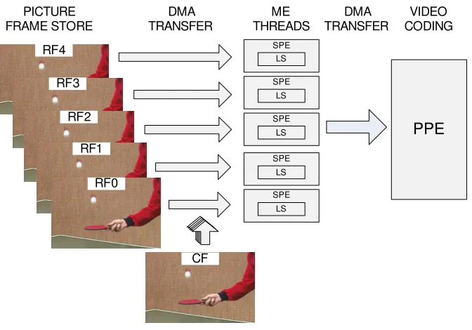
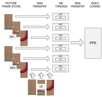
Figure 2.1 shows the proposed parallelization approach. It exploits data parallelism by applying the same search algorithm to the different RFs on the various SPEs. The optimal configuration of the H.264/AVC video encoder in terms of quality versus bit rate uses 5 different RFs. Therefore, with this approach, up to 5 SPEs can be used if we want resources to be busy. Pixels from different RFs are loaded from the frame to the SPEs’ LS, while pixels from the CF are loaded at the same time in the LS of all SPEs. When the ME process is finished, results are passed back to the PPE, that is responsible for the remaining components of the video coding process.
ME is running in threads in parallel with the main VC process. When results are received, ME for the next row can start and run in parallel with the rest of the VC, as it is shown in Figure 2.2.
An SPE has access to the data frame in chunks according to the MB organization. Each data chunk is composed by a row of MBs from the CF and a row of SAs from RF. The pixels in a data chunk are loaded into the LS of an SPE doing one DMA transaction. This “row oriented” approach is used to maximize data reuse: for the first row of MBs and SAs all pixels have to be loaded, but for the next ones only the pixels not present in the intersection of two consecutive rows of SAs have to be transferred. Figure 2.3 shows the initial data from both CF and RFs that need to be loaded, as well as the additional pixels that need to be loaded for the next two MB/SA rows in two individual DMA transactions. Figure 2.3b)illustrates the SAs that have to be loaded in consecutive rows; only non-overlapping regions have to be transferred to the SPEs’ LS.
In the rest of the paper, a MB is considered to have 16×16 adjacent pixels and all sub-units in a MB, independently of their size, will be calledsub-blocks. The order by which the MB and sub-blocks are processed is decided by the SPEs. Process is repeated for each MB in a row. When all MB are processed, the calculated Motion Vector (MV)s and the distortion measures are passed back to the PPE in a single DMA transaction.
Synchronization points are introduced whenever DMA transfers for either pixels or results are finished, allowing data buffers reuse. It is worth to notice that, in the case of specialized processors, memory is a sparse resource; and it could be very useful to save memory for robust search algorithm implementation purposes.
RF4
RF3
RF2
RF1
RF0
CF
SPE LS
SPE LS
SPE LS
SPE LS SPE
LS
PPE
PICTUREFRAME STORE
DMA TRANSFER
ME THREADS
VIDEO CODING DMA
TRANSFER
Fig. 2.1.Parallelization approach.
ME
SPE0
PPE
time
.
. .
ME delay
SPE1
MEMC
ME
SPE2
Transf. Quant.
. . .
. . . . . .
wait wait
wait
Fig. 2.2. Time diagram of described VC approach.
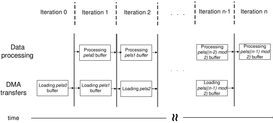
iteration for each MB row (n is the number of MB rows). Firstly, in Iteration 0, each SPE loads the initial row of MBs and the corresponding row of SAs in thepels0 buffer. In the next iterations, in parallel with the processing of data inpels(i mod 2)buffer, data are loaded into thepels((i+1) mod 2)buffer. After each iteration exits a synchronization point is introduced, in order to ensure that data to be processed in next iterations is already loaded into the LS. It is important to mention thatndoes not represent the number of rows in a frame, but the total number of rows for the whole sequence, because the loading of the first row of the next frame can be performed in parallel with the processing of the last row of the current frame. In such a way the pipeline processing/loading is maintained, saving the time required to individually transfer the initial row.
SA0
UPD_SA2 UPD_SA1 MB0
a) b)
SA1
SA2
CF RF
MB1
MB2
Fig. 2.3.Frame division for data transfer: a) current frame b) reference frame.
Loading pels0
buffer
Loading pels1
buffer Processing
pels0buffer
DMA
transfers
Data
processing
time
Loading pels2
Processing
pels1 buffer
Loading
pels((n-1) mod
2)buffer
Processing
pels((n-2) mod
2)buffer
Processing
pels((n-1) mod
2)buffer
Iteration 0 Iteration 1 Iteration 2 Iteration n-1 Iteration n
≈
.
. .
. . .
Fig. 2.4.Double buffering in proposed algorithm.
2.2. Scalable algorithm. The proposed basic parallel algorithm is efficient but it does not scale, in the sense that the maximal parallelism achieved, which means in this case the maximal number of used cores is limited by the number of RFs. In order to achieve a scalable algorithm, CF and related RFs can be divided in sub-CFs and sub-RFs, corresponding in this case to vertical slices. An example with 6 SPE cores and 2 RFs is presented in Figure 2.6. The scalable algorithm is obtained by applying the basic parallel algorithm to the sub-CFs and the sub-RFs, wich can be seen as full CF and RF. A slight overhead is introduced to organize the vertical slices, but the advantage is that the algorithm is able to use any number of cores to perform in parallel the ME independently of the number of RFs used. The same approach can be followed if the video sequence resolution is so high, that a single MB/SA row can not fit in the LS.
3. Motion Estimation.
SPE
PPE
time
fill k+1
SPU
MFC
VC k-2 wait ME k-1
read k
send res
VC k-1 fill k+2
read k+2 read k+1
ME k
wait send res
VC k ME k+1
wait wait
Fig. 2.5.Data flow and phases in an iteration of proposed diagram.
SPE LS
SPE LS
SPE LS
SPE LS SPE
LS
SPE LS RF1
RF0 PICTURE FRAME STORE
DMA TRANSFER
ME THREADS
VIDEO CODING DMA
TRANSFER
PPE
CF
Fig. 2.6.Scalable parallelization approach.
achieved by using mailboxes. By a matter of organization, the PPE program is presented first, followed by the SPE program, and at the end, the way of using the SIMD instruction extensions to exploit further parallelism and additionally speed up is given.
Algorithm 1PPE side of the algorithm
1: allocate buffers, create and initialize threads 2: calculate the required number of vertical slices 3: foreach P frame and rowdo
4: ifrow is first and frame is firstthen 5: ppu msg =N EW F RAM E 6: else
7: ppu msg =N EW ROW 8: end if
9: ifrow is not lastthen
10: foreach vertical slice and RFdo 11: fill the buffer of the related thread 12: end for
13: send ppu msg to threads 14: end if
Ensure: confirmation is received 15: end for
16: send KILL message to threads
that,pels0,pels1 andresultsbuffers are allocated for each thread, the threads are created, and, finally, initial parameters are passed to the SPEs. The addresses of the related buffers are also sent to the SPEs.
For each P frame the following actions are performed: i) A row of MBs/SAs is loaded into the buffers corresponding to the different vertical slices and RFs;ii) when the buffers are filled a message is passed to each thread in order to start the DMA transfer for the next row or the next frame if the last row of the previous frame was already transferred. The reason for distinction betweenN EW ROW andN EW F RAM Emessages is that the SA chunk for the initial row in a frame has a different size, as it was shown in Figure 2.3; andiii) the PPE waits for the ME results and for the confirmation message from each thread that a row is finished. The time passed since entering in the loop till the confirmation message is received corresponds to the time that VC has to wait for ME to be finished, and it is called ME row delay. By summing all the ME row delays in a frame we get the ME time for a single frame. When all P frames are examined, a KILL message is sent to SPE threads.
3.3. SPE. SPE threads implement the search algorithm according to the steps represented in Algorithm 2. The algorithm is divided in three main parts: i) the first one performs direct communication with the PPE, ii) the second part is responsible for the buffers’ management, and iii) the final part implements the search algorithm.
The first part initializes the process and starts the infinite loop, waiting for the PPE commands. The initialization part includes allocation of the buffers, namely pels0, pels1 and results, and the registration of the DMA addresses, namely pels0addr, pels1 addr and results addr. These addresses are set up with the correspondingpels0,pels1 andresultsbuffer lines, on the PPE side. The NEW FRAME, NEW ROW or KILL messages are expected in mailboxes during the execution of the infinite loop. If NEW FRAME or NEW ROW messages are received, the algorithm reaches the first synchronization point, which means that the pixels of the current row are loaded. Then the SPE starts the loading of the next row pixels in parallel with the processing of the current row. If it is the initial row, an initial delay has to be introduced, because no data exists to be processed in parallel. In the case of NEW FRAME message all SA pixels in a row have to be loaded, while in the case of the NEW ROW message, just the new pixels are loaded while the ones that belong to the previous SA row are reused, (see Figure 2.3). When the ME of current row is finished, the results are sent back to the PPE.
The third part (line 16) corresponds to the implementation of the search procedure. The search procedure is not the aim of this work, so the proposed parallelization approach considers the implementation of both computationally intensive and robust search algorithms (requiring less computation but more memory). After processing a whole MB row, the content of the resultbuffer is passed to the main memory (PPE) by a DMA transfer. When the transfer is finished, a confirmation message is sent to the PPE notifying that the results are available and can be used by VC. The algorithm is finished when a KILL mail is received.
the SAD defined in eq. 3.1, for different pixels:
SAD(vx, vy) = NX−1
m,n=0
|CF(x+m, y+n)−RF(x+vx+m, y+vy+n)|, (3.1)
where (vx,vy) are coordinates of the MV referring to the SA and (x,y) are the coordinates of the left-up angle
of the considered MB referring to the frame.
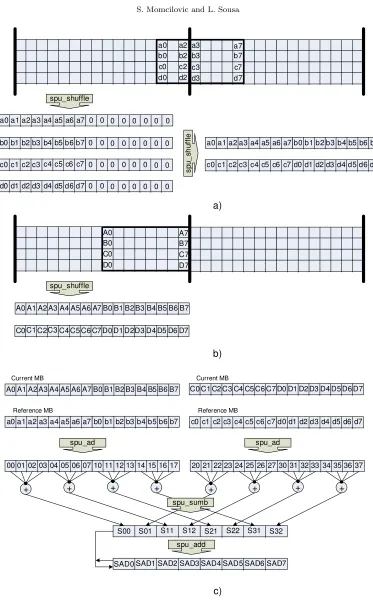
As it is well known, data misalignment is one of the main constraints when using vector instructions. The SPE loads and stores only support quadword (16-byte) aligned data, masking the 4 least significant bits of the address. However, search algorithms for ME run in a pixel-by-pixel basis, therefore requiring pixel based (misaligned) data access and calculation. In the proposed data alignment scheme presented in Figure 3.1 data is packed in aligned byte element vectors using the instructions from the SPE SIMD intrinsics library. Specialized
spu shuf f leintrinsic combines the bytes of two vectors, according to the organization defined in a third vector. The required alignment patterns are stored in a pre-calculated look-up table in SPE LS. Two typical aligning situations of both misaligned MB and SA are presented in Figure 3.1 a) and b), respectively. Each MB line is placed in a single 16Bytes area, because the first MB starts from an aligned position, and the MB width of 16 pixels is used. Therefore, the sub-block lines can only be “shifted” inside of a single 16Bytes aligned area. However, SAs’ vectors can be divided between two successive 16Bytes areas, and in this case one additional
spu shuf f leinstruction has to be used.
Figure 3.1c)depicts the SAD value calculation. The scheme is similar to the one proposed in [9]. First the absolute difference (spu ad intrinsic) vectors are calculated for the SA and MB values packed in byte vectors. Then thespu sumbintrinsic instruction is applied in order to sum each 4 elements of the vectors in 16bit result values. Finally, the obtained values are accumulated in the SAD vector.
The same SIMD processing scheme is adopted in the PPE, with the exception that the luminance of the pixels in the JM 14.0 encoder is stored asunsigned shortvalues, which has a negative impact in the obtained speedup.
Algorithm 2SPE side of the algorithm
1: allocate buffers 2: read buffer addresses 3: repeat
4: read in mailbox 5: ifmsg=KILLthen 6: end algorithm 7: end if
8: ifmsg=N EW F RAM Eormsg=N EW ROW then 9: ifmsg=N EW F RAM E then
10: increase DMA transfer size 11: end if
12: ifrow is initialthen 13: load first row pixels 14: end if
Ensure: DMA transfer of current row pixels is finished 15: start loading of next row
16: process current row
17: send results and confirmation
Ensure: DMA transfer of results is finished 18: end if
19: untiltrue
4. Experimental Results. The experimental results are obtained by using the JM 14.0 software imple-mentation of H.264/MPEG-4 AVC. Seven different sub-block types and 5 RFs are considered. The optimal FSBM and adaptive Unsymmetrical-cross Multihexagon-grid Search (UMHS) search algorithms are both pro-grammed. All frames except the first one are coded as P-frames, with the ME search range of 16 pixels, and a quantization step QP=28. Both Common Intermediate Format (CIF), 352×288 pixels, and HD, 720×576 pixels, test video sequences are used. Sequencesakiyo,busandf oremanfor CIF andblue sky,riverbedandrush hour
a2
a0 a7
b0 a3
b2 b3 b7
c0 c2
d0 d2
c3 d3
c7 d7
a0a1a2 a3a4 a5 a6 a7 0 0 0 0 0 0 0 0
b0b1b2 b3b4 b5 b6 b7 0 0 0 0 0 0 0 0
c0c1c2 c3c4 c5 c6 c7 0 0 0 0 0 0 0 0
d0d1d2 d3d4 d5 d6 d7 0 0 0 0 0 0 0 0
spu_shuffle
s
p
u
_
sh
u
ff
le
a0a1a2 a3a4 a5 a6 a7 b0b1b2 b3b4 b5 b6 b7
c0c1c2 c3c4 c5 c6 c7 d0d1d2 d3d4 d5 d6 d7
A0 A7
B0 B7
C0 D0
C7 D7
spu_shuffle
A0A1A2 A3A4 A5 A6 A7 B0B1B2 B3B4 B5 B6
C0C1C2C3C4 C5 C6 C7 D0D1D2D3D4 D5 D6 D7
B7
A0A1A2 A3A4 A5 A6 A7 B0B1B2 B3B4 B5 B6 B7
a0a1a2 a3a4 a5 a6 a7 b0b1b2 b3b4 b5 b6 b7
Current MB
Reference MB
spu_ad
000102 0304 05 06 07 101112 1314 15 16 17
Current MB
Reference MB
spu_ad
202122 2324 25 26 27 303132 3334 35 36 37
C0C1C2 C3C4 C5 C6 C7 D0D1D2 D3D4 D5 D6 D7
c0c1c2 c3c4 c5 c6 c7 d0d1d2 d3d4 d5 d6 d7
S01 S11 S12 S21 S22 S31 S32
S00
+ + + + + + + +
spu_sumb
SAD0 SAD1 SAD2 SAD3 SAD4 SAD5 SAD6 SAD7 spu_add
a)
b)
c)
Fig. 3.1.Data alignment and SAD calculation process on the SPEs: a) MB alignment b) SA alignment c) SAD calculation
Table 4.1
ME time (ms) per frame for the different systems and search algorithms
C E L L C P U P P U
UMHS FSBM UMHS FSBM UMHS FSBM
akiyo CIF 18 349 352 3995 532 2382
bus CIF 79 348 695 4001 893 2356
foreman CIF 48 348 502 3998 703 2372
blue sky 720×576 205 1530 2105 16859 3357 10151
riverbed 720×576 286 1530 3117 16842 4238 10172
rush hour 720×576 188 1530 1870 16863 2179 10191
Table 4.2
Required SPU memory in kBytes
Program Data Total
without SIMD instr. 14.1 4 18.5
with SIMD instr. 15.5 5.5 21
UMHexagonS+SIMD 16.5 6.0 22.5
Table 4.1 presents the time required for ME in the Cell processor (proposed one), as well as in the PPU and the CPU; for both UMHS and FSBM algorithms. Results prove the efficiency of the multi-core solution compared with single core solutions on CPU and PPU. Even without partially hiding the ME behind the VC, the real time ME for the CIF format is nearly achieved, when UMHS algorithm is used.
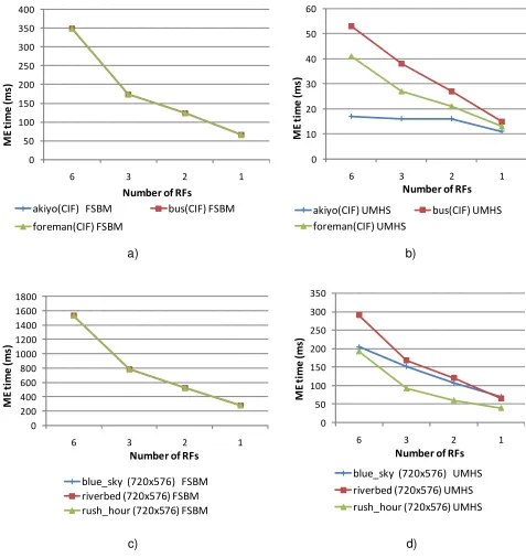
In figure 4.1 the four different charts show the scalability of the proposed algorithm regarding the indepen-dence between the number of threads and the number of RFs used, as well as video sequence resolution, when 6 SPUs are used. In the cases when less than 6 RFs are used, all the CF and the RFs are divided in vertical slices, namely 2, 3 and 6 slices, for 3, 2 and 1 RFs, respectively.
Figures 4.1 a) and c) show results for the optimal FSBM algorithm but with different resolutions. As it is shown in the charts for both resolutions a regular ME time decrease is obtained using the parallel algorithm with the reduction of RFs, or, what is equivalent, with the increase in the number of vertical slices considered for each frame.
Figures 4.1 b) and d) show results for the UMHS search algorithm. In both charts it is visible a trend of ME time decrease, with increase in number of vertical slices that each frame is divided in (inversely proportional to the number of RFs). A faster ME time decrease with the increase in the number of vertical slices when the motion is spatially more balanced, as in thebusandriverbedsequences, is also visible. In the case ofriverbed
sequence the curve evolution is very similar to the one for the FSBM algorithm, because motion is quite well spatially balanced.
Figure 4.2 presents the time that the remaining part of VC has to wait for the ME to be finished, which includes preparation of the buffers and communication between the PPU and SPUs. The ME for the next MB row is running in parallel with the VC of the current MB row, and, therefore, ME is almost hidden behind the VC time.
Figure 4.3 shows that ME is no longer the bottleneck of video coding if the proposed encoder is used. In the case when either PPU or CPU is used, ME takes up to 95% of encoding time, as it was already reported, but in the presented approach it takes less than 15%. Results are even better if HD video sequences are used, because VC time increases more than the ME delay.
Table 4.2 presents the SPU memory required by the proposed motion estimator. The values show that a very small part of the 256kByte total LS is used (less than 15%), and therefore there is plenty of space for fast algorithms development, which can require a lot of memory. The presented result for UMHS includes only spatial prediction. If a full version with the temporal prediction is used the MVs and distortion measures for multiple frames need to be stored, and up to 30kBytes per prediction frame is required for temporal prediction [3], if CIF format is considered.
a)
b)
c)
d)
0 200 400 600 800 1000 1200 1400 1600 1800
6 3 2 1
M
E t
im
e (
m
s)
Number of RFs
blue_sky (720x576) FSBM riverbed (720x576) FSBM rush_hour (720x576) FSBM
0 10 20 30 40 50 60
6 3 2 1
M
E t
im
e (
m
s)
Number of RFs
akiyo(CIF) UMHS bus(CIF) UMHS foreman(CIF) UMHS
0 50 100 150 200 250 300 350 400
6 3 2 1
M
E t
im
e (
m
s)
Number of RFs
akiyo(CIF) FSBM bus(CIF) FSBM foreman(CIF) FSBM
0 50 100 150 200 250 300 350
6 3 2 1
M
E t
im
e (
m
s)
Number of RFs
blue_sky (720x576) UMHS riverbed (720x576) UMHS rush_hour (720x576) UMHS
Fig. 4.1.Time(ms) per frame for 6 SPUs, considering different number of RFs, video formats and search algorithms: a) CIF video format and FSBM b) CIF video format and UMHS c) 720×526 resolution and FSBM b) 720×526 resolution and UMHS
! " # $ % & '( ) *+,*-.*/0*
1223456
122 674
833456
83 674
8833456
883 674
Fig. 4.2.ME delay (ms) per frame for the different implementations of ME.
9:99; <9:99; = 9:99; > 9:99; ?9:99; @9:99; A 9:99; B9:99; C9:99; D9:99; <99:99; E F G HI JKL MN O JKL P IQRSET JKL MUN R VOFH B=9W@BA Q G XRQ M RY B=9W@BA Q N OZVZI N Q B=9W@BA [ \ ] ^ _ ` ^ a b c b d ^ e a f g c e h ^ ij k
lmnlo plqrl
Jsttuvwx
JsttLxyv
Jzuuvwx
JzuLxyv
zzuuvwx
zzuLxyv
Fig. 4.3.Percentage in total encoding time for the different motion estimators.
frames and full pixel accuracy are considered. Moreover, it is shown that the CELL processor is able to perform ME in real time for CIF images, if the optimal full search approach is adopted.
REFERENCES
[1] J. Ostermann et al, Video coding with H.264/AVC: tools, performance, and complexity, IEEE Circuits and Systems Magazine, vol. 4, pp. 7–28.
[2] S.-Y. Huanga and W.-C. Tsai,A simple and efficient block motion estimation algorithm based on full-search array archi-tecture, Signal Processing: Image Communication, vol. 19, pp. 975–992, 2004.
[3] Z. Chen et al,Fast integer-pel and fractional-pel motion estimation forH.264/AVC, Journal of Visual Communication and Image Representation, October 2005, pp. 264–290.
[4] S. Momcilovic, N. Roma, and L. Sousa,AnASIPapproach for adaptive motion estimation onAVC, Proceedings of the IEEE 3rd Conf. on Ph.D. Research in Microelectronics and Electronics (PRIME 2007), Bordeux, France, July 2007, pp. 165–168.
[5] J.-C. Chu et al,An embedded conherent-multithreading multimedia preocessor and its programming model, Proceedings of the 44th Design Automation Conference (DAC 2007), San Diego, California, USA, June 2007, pp. 652–657.
[6] C. R. Johns and D. A. Brokenshire,Introduction to the cell broadband engine architecture, IBM Journal of Research and Development, vol. 51, no. 5, pp. 503–519, September 2007.
[7] Sony Computer Entertainment Incorporated, SPU C/C++Language Extensions, 2005. [8] L.-K. Lui et al,Video alalysis and compression on theSTI CELLbroadband engine, Tech. Rep.
[9] L. B. Shyang,A Simplified High Definition Video Encoder Based on TheSTI CELLMultiprocessor, Student thesis, Institu-tionen f¨or systemteknik, Link¨oping, Sweden, January 2007.
[10] S. Momcilovic and L. Sousa, An parallel algorithm for advanced video motion estimation on multicore architectures, Proceedings of the 2nd International Conf. on Complex, Intelligent and Softare Intensive Systems (CISIS 2007), Barcelona, Spain, March 2008, pp. 831–836.
[11] International Business Machines (IBM) Corporation, CELLBroadband Engine Programming Tutorial, 2006.
[12] M. Gschwind,TheCell Broadband Engine: Exploiting multiple levels of parallelism in a chip multiprocessor, International Journal of Parallel Programming, vol. 35, pp. 233–262, 2007.
[13] JVTReference Software unofficial version 12.0,http://iphome.hhi.de/suehring/tml/download
Edited by: Sabri Pllana, Siegfried Benkner Received: June 16, 2008
![Figure 3.1 c)Then theabsolute difference ( depicts the SAD value calculation. The scheme is similar to the one proposed in [9]](https://thumb-us.123doks.com/thumbv2/123dok_us/8750979.1748562/7.595.46.534.453.671/figure-theabsolute-dierence-depicts-calculation-scheme-similar-proposed.webp)