ISSN: 1942-9703 / © 2016 IIJ Abstract-- Transportation has increasingly become an
important component in the national economy and daily life. So it is necessary to build a modern intelligent vehicle navigation and lane change assistance system. The system will help to reduce the traffic congestion on roads, provide better lane changing assistance to drivers, prevent over speeding and over taking of vehicles and reduce accidents. The main objective of the proposed system ENLC (Embedded Vehicle Navigation and Lane Changing Assistance System) is to operate the vehicle in safe speed at critical zones and proper real time lane changing assistance. The data (speed of the vehicle, position, lane etc.,) capture takes place in the designed system for the purpose to monitor the driving behavior of the driver. When the vehicle is in danger of leaving the lane unintentionally the system will deliver a warning to the driver of that vehicle and also to the nearby vehicles. It is integrated with the technology of the GSM and the GPS for the accurate tracking of the vehicle. The system also sends faulty driving message and emergency warning message to the traffic monitoring authority. The micro-controller plays a crucial role in the system in terms of the implementation and the interfacing of the external modules and carrying out the lane-changing algorithm. The test bed is created on the present method where a lot of analysis takes place in the On Board Embedded System designed for Vehicle Navigation. The designed system was tested on a 4-lane road at Neemrana in India. Successful simulations have been conducted along with real time network parameters to maximize the QoS (quality of service) and performance using SUMO and NS-2. We have compared the AODV and GPSR routing protocols in changing topology and high mobility with respect to our algorithm. The quality of service is studied on the basis of end-to-end delay and packet loss ratio.
Keywords— Embedded Systems, GSM, GPS, OBU, PIC- Microcontroller, RSU, Real-time systems, Sensors, V2V, V2I, Zigbee.
I. INTRODUCTION
AKING the upcoming model of driverless cars and smart cities into consideration, it is very important to build up mobility models and algorithms for safe and efficient environment. Nowadays road facilities are a major concern in the developed world. Recent studies show that one third of the number of fatal or serious accidents are
Manuscript received June 4, 2015. This work was supported in part by NIIT University, Neemrana, Rajasthan, India.
Yash Agarwal is with the Department of Electronics and Communications Engineering, NIIT University, Neemrana, Rajasthan, India. (e-mail: [email protected]).
Kritika Jain is with the Department of Electronics and Communications Engineering, NIIT University, Neemrana, Rajasthan, India. (e-mail: [email protected])
Jitendra Joshi is with the Department of Electronics and Communications Engineering, NIIT University, Neemrana, Rajasthan, India. (e-mail: [email protected]).
associated with excessive or inappropriate speed, as well as the abrupt lane changing activities. Reduction of the number of accidents and mitigation of their consequences is a big concern for traffic authorities, the automotive industry and transport research groups. One important line of action consists in the use of advanced driver assistance systems, which are acoustic, visual signals produced by the vehicle itself to communicate to the driver about the possibility of a collision.
Vehicle navigation and lane changing assistance systems (VNLC) have been recently developed that use a combination of global positioning systems (GPS) and digital maps obtained from a Geographical Information System (GIS), to assess threat levels for a driver during the Lane Changing and Over Speeding.
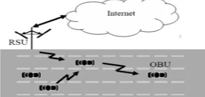
Likewise, intelligent speed assistance systems warn the driver when the vehicle’s velocity is inappropriate, using GPS in combination with a digital road map containing information about the speed limits of the various sections of the roads. The Fig. 1 shows us the communication between the vehicles, RSU (small distributed road side monitoring station) and the central server (centralized traffic monitoring Server).
Fig. 1 Communication model (Vehicle-RSU-Central server)
The road tracks have been assigned with particular speed limits respectively and the vehicles moving on them will have to follow the prescribed speed limits. We have taken up a scenario where we have five different tracks on a road with the speed limit increasing from the left most tracks to the right most one. The left most track is the emergency track where only the police and ambulance can enter and the right most one is the stop track where the vehicles do not move. The model is therefore like 120Kmph->80Kmph->40Kmph->0Kmph(stop) (with a 5% tolerance). The vehicles have to move according to the speed limits set above. While moving on these tracks, the vehicles can increase or decrease their speed and change the tracks accordingly. Changing the tracks will be possible only when the minimum gap between the vehicles is as set in the algorithm. But if any particular vehicle is not doing so, the hardware implemented OBU (On Board Navigation Unit) in the vehicle will display a warning message to the driver to
ENLC: Embedded Based Vehicle Navigation
and Lane Change Assistance System
Yash Agarwal,
Student Member, IEEE
, Kritika Jain and Jitendra Joshi
either change the speed or change the track. If the defaulter vehicle does not follow the speed rules and over speeds and creates unsafe environment, then the emergency warning message will be broadcast to the surrounding vehicles and the central monitoring system via SMS or by some dedicated spectrum (radio modules corresponding to DSRC spectrum) for the communication among them so as to maintain a safe environment. The other vehicles will receive the information and this information will influence their movement in a particular fashion. As soon as the defaulter messages increase in number, the central traffic monitoring system will send the message to the OBU that will automatically slow the speed of engine and will be pushed to off. After the engine turns off, it cannot start without a password generated by the central monitoring system. Vehicle tracking systems are also accepted in consumer vehicles as a theft prevention and retrieval device.
In this model we are using the concept of lane changing with respect to speed, with the help of the information received from the GPS receiver. The latitude and longitude data will be parsed and then we will check the current position of the vehicle with respect to the lane. If the driver does not drive at the correct speed then the driver will be warned first in terms of alarm and displaying message on the LCD, this process will repeat for some duration. After the elapsed time the warning message will be broadcast to the nearby vehicles and RSU’s. The GPS receiver gives us real time data and so the implementation of this technique will be more qualitative as other substitutes to GPS are not much reliable and efficient either.
The rest of this paper is organized as follows: In section II we have taken a brief look at the concept of Vehicle Navigation and lane changing assistance systems and the related work done in this field. In section III, we have discussed the system design and problem formulation. In section IV, we have defined our protocol. In section V we have shown the performance evaluation, taken a look at the applications of GPS and the hardware implementation of the protocol, traffic model generated with the help of SUMO-MOVE followed by the simulation of the ad hoc wireless network in NS-2. Section VI, concludes this paper and gives a glance of future work to be done in this model. Lastly, we have listed the references.
II. RELATEDWORK
In this section, we discuss the relevant works done in this field, outline our contributions and work. The relevant work can be categorized as literature on vehicular ad hoc networks and literature on real time safety applications for on road vehicles and drivers.
VANET uses cars as mobile nodes in a mobile ad hoc network to create a mobile network [1].
In a vehicle based ad hoc wireless network every node represents a car moving in a particular range and it can communicate with the other nodes (both static and dynamic) in a specific range. There are many tools available for generating road traffic environment for VANET such as VanetMobiSim, SUMO, VISSIM etc. whose output can be further integrated with network simulators like NS-2.
In [2] the paper discusses about the smart broadcasting of the messages in VANET. This will help in improving the efficiency and also security up to some extent.
In [3] the thesis proposes a method to calculate the speed of the vehicle based on the position of the vehicle. The vehicles exchange information with RSU and then the RSU sends it to the central monitoring server. The central server based on the time and positions received determines the average speed of the vehicles. In this method, there may be an instance where the time taken for the exchange information cycle is more and the data may not be very accurate at that very position. The GPS receiver takes care of this scenario as there is no computation involved and moreover the GPS receiver is receiving and giving us real time information.
In [4] the paper proposes a method of vehicle detection and speed estimation based on RF. The main drawback is that a vehicle can proceed to any speed in case of a miss, which can cause an error in the accurate estimation of speed. In [5] the paper throws light on various technical applications, advantages, challenges and issues in VANET and methods to improve the network system. The paper also discusses about the techniques involved in secure message transmission, which will help us in our future work foe data authentication.
In Rubini.R, et al [6] proposed a system has an alerting, recording and reporting system for over speed violation management. The Zigbee transmitter sends the speed limit of the particular lane entered by the vehicle and also gives alerts like “road works”, “steep slopes”, and “school zone” in the form of acoustical messages and also in LCD.
In S.P. Bunker, et al [7] described a real-time online safety prototype that controls the vehicle speed under driver fatigue. The purpose of such a model is to advance a system to detect fatigue symptoms in drivers and control the speed of vehicle to avoid accidents. The main components of the system consist of number of real time sensors like gas, eye blink, alcohol, fuel, impact sensors and a software interface with GPS and Google Maps API’s for location.
In this work, we have introduced a novel lane change and emergency message broad cast technique for on road vehicles. We have developed a partially functional prototype to detect the speed of the vehicle and transmit the emergency messages on real time basis. We simulated the algorithms with SUMO and NS-2 and calculated the average end-to-end delay and packet loss ratio with respect to the speed and the number of vehicles to determine the quality of service and the effectiveness of our system design.
III. SYSTEMDESIGNANDPROBLEMFORMULATION Vehicle driving behavior will depend on many factors like situation, over speeding, fast lane changing, density of traffic etc. Therefore, driving recklessly will cause accident and also effect the traffic movement. Now if someone drives the vehicle in a faulty way and does not follow the lane changing and lane speed limit rule then fast action must be taken to stop that vehicle and warning message will have to be sent to the surrounding vehicles and the traffic monitoring server about the abrupt behavior of the faulty vehicle in the given road segment. If someone is driving in speed-restricted zone, then how can driver be alerted during that situation is the challenge.
ISSN: 1942-9703 / © 2016 IIJ to minimize it? Can there be any assistance system to
prevent abrupt lane changing in real time?
How can we integrate fast real time navigation and assistance system together?
Also how can we send faster warning message to the neighbor vehicle about the situation? Can we minimize the latency and increase the quality of service by using appropriate routing algorithm?
IV. PROPOSEDMETHOD A. Navigation and Lane assistance System
In this proposed work, the On Board System for Vehicle Tracking and Lane Change Assistance is used to track the faulty over speeding vehicle by using GPS and GSM technology and send the warning message to the surrounding vehicle to avoid the collision situation.
The locking system is also incorporated which is used to track the theft of the vehicle. The locking system goes into sleeping mode while the vehicle is handled by the owner of the vehicle and goes active otherwise. The mode of operation can be changed in person or remotely. If any interruption occurs in any side of the door, the IR sensor senses the signals and an SMS is sent by the microcontroller. The controller issues the message about the location of the vehicle to the car owner or authorized person. After that all the doors get locked. To open the door, authorized person needs to enter the password. The OBU helps in lane change assistance and giving alerts to the driver when over speeding is detected. If driver intentionally breaks the rule for longer duration after warned then the message is broadcast to the surrounding vehicles and to the central traffic monitoring authority through the RSU’s. The central authority can take the necessary disciplinary action later by stopping the vehicle just by sending an SMS to the On Board System.
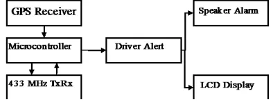
The lane detection sensor and the ultrasonic obstacle sensor are for detecting the lane of the vehicle and any object around the vehicle respectively. In future, the OBU can be interfaced with an accident sensor, heart beat sensor for the safety purposes like opening the airbags and providing oxygen masks respectively. The Block diagram of navigation and lane change assistance system based on GSM and GPS technology is shown in the Fig.2.
Fig. 2: Block diagram of the system based on GSM and GPS
B. OBU: GPS-GSM enabled monitoring system
It is the hardware that processes the data received by GPS with respect to the moving vehicle. The GPS receiver receives the data packets from the satellites and feeds it to the microcontroller [8]. The micro-controller further parses the required data and stores the lane information in Lane ID
buffer and checks it with the lane threshold value set in the system. In case of any mismatch, the microcontroller alerts the driver three times. Now if the driver ignores these warnings and continues to break the rules, the message is then broadcast to the other vehicles and RSU’s in range.
The hardware implementation of the OBU described above is as shown in the Fig. 3.1 and 3.2. The Fig. 3.1 corresponds to the connection circuit diagram of the prototype and the Fig. 3.2 corresponds to the hardware device designed by us.
Fig. 3.1 Schematic diagram of the hardware prototype
Fig. 3.2 Prototype device
The hardware of this model comprises of an embedded system comprising a PIC microcontroller interfaced with a GPS receiver with baud rate of 9600 bps, an LCD display, GSM Module, alarm and a radio module for displaying the warning message, alerting the driver and broadcasting the warning messages respectively. The GSM module is used to exchange SMS’s with the central authority. The location, speed and time information will be sent to the RSU in order keep proper track of the faulty vehicle and pass on information further to the central traffic monitoring server. The protocol was developed to implement the efficient lane changing based on the speed of the vehicle for the sake of safety and reduce on-road accidents.
C. Assumptions
The Speed Based Lane Changing algorithm is based on the following assumptions:
• [9] Every vehicle is capable of determining its own location and mobility information with the help of GPS.
• The information being exchanged between the vehicles and RSU’s is authentic.
• The hardware installed in the vehicles is running on the power provided by the vehicle itself.
• All the vehicles moving on these lanes are VANET approved and have the hardware installed in them. Before we start with the algorithm, here are a few definitions:
are the start and end points of the lane respectively with (x, y) as the location (x=latitude, y=longitude). l is the number of lanes (5 according to our scenario). vl is the speed of the
lane. The length of the road segment and the width of the lanes can be estimated with the help of the location of s and
e.
Definition 2 (Road Network): Road network is a graph
Rn=(j, s). Here j is the set of all road segment junctions and
s is the set of all road segments.
Definition 3 (Navigation Path): The navigation path is given by Np is a set of connected road segments and
junctions.
Definition 4 (Vehicular Network): A vehicular network is a mobile ad hoc network with all the vehicles acting as nodes.
Definition 5 (Traffic Density): The traffic density of a road is defined as the number of vehicles present on the road per unit length per lane.
Definition 6 (Minimum Gap): It is the minimum gap to be maintained between two vehicles on any particular lane on the road. It is calculated using the basic distance formula using the coordinates of the vehicle. In the present case, we have ignored the effects of elevation on the vehicles. In this algorithm it is denoted as mingap.
Parameters:
Assume that there are 3 lanes Li = {L1, L2, L3} with speed
limits (Vi)={V1, V2, V3} respectively with a tolerance of
10%.
LBi is the lane buffer ID, which will help us in storing the
previous lane ID in which the vehicle was moving.
Vui and Vli are the upper and lower limits of the lane Li.
(Each lane has its own upper and lower limit). The vehicles at the start point initiate the entire path planning process travelling in various lanes L1, L2 and L3 at different speeds Si={S1, S2, S3}(speed of the vehicles).
GPS will monitor LBi and help to locate the last lane ID,
position and speed to store in Buffer of the monitor system. Now suppose that a vehicle is travelling with speed Sest in
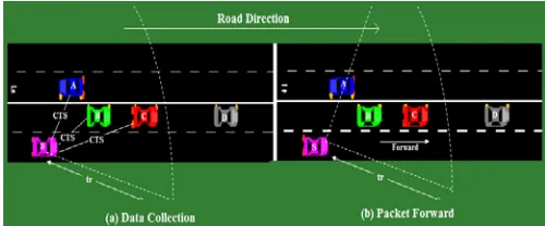
lane L3 having a upper and lower speed limit lane at a particular point, the GPS based monitor system will check the speed of this vehicle with lane speed limits and give an alert message to the driver to either reduce/increase the speed or to change the lane, if driving at wrong speed. The system continuously monitors the driving style of the vehicle for a particular time t. The collection algorithm uses an RTS, CTS schemes to collect traffic information as well as build neighbor table (NT). This procedure can be illustrated as in Fig. 4. When the forwarded packet is received by vehicle S, it will firstly broadcast RTS with its own position information to all one-hop neighbor vehicles. Then neighbors will response by sending a CTS packet together with the vehicle information. All the received vehicle information will be used to build the neighbor table but only vehicles with the same directions as the road segment will be stored and estimated later because the opposite side traffic conditions make no contribution to path planning.
If the vehicle changes the lane or reduces the speed in the time t the monitor system gives an OK status to the driver and to the RSU. Whenever the request packets for lane changing arrive for a new road segment, the speed
estimation algorithm takes information from the neighbor table NT is executed to estimate the traffic speed of the newly collected road segment and then the system checks for the mingap for proper lane change.
Suppose the faulty vehicle does not correct its lane after a prescribed about of time then the OBU monitoring system will broadcast the emergency message to neighbor vehicles and also send emergency data packet to nearby RSU by using the affective Greedy based Routing protocol.
Fig. 4 Scheme for smart transmission of data
D. SBLC Algorithm
Taking the above assumptions and definitions into consideration, we have the Speed Based Lane Changing algorithm as follows:
Position Verification:
Obtain the values of Sest, Vli, Vui, w.r.t Li
Pos-label
if (Sest<Vui) AND (Sest>Vli)
then
Alarm OFF;
Display “ok speed message to driver”; Display “Sest to driver”;
elsif (Sest>Vui)
Display “decelerate or lane change”; Alarm on;
Timer on;
Check for deceleration, lane change subroutines;
Timer ends;
Refresh the neighbor table NT;
Greedy forward of the warning message to RSU, neighboring vehicles;
goto Pos-label else (Sest<Vli)
Check for engine state if engine off
then Display “Vehicle stopped”; else
Display “Vehicle moving ”; Alarm on;
Timer on;
Check for acceleration, lane change subroutines; Timer ends;
Refresh the Neighbor table NT;
Greedy forward the warning message to RSU, neighboring vehicles;
ISSN: 1942-9703 / © 2016 IIJ
Deceleration/Acceleration:
1. if (Sest<Vli) Accelerate Check for Sest
Check mingap
goto Position Verification 2. if (Sest>Vui)
Decelerate Check for Sest
Check mingap
goto Position Verification
Lane Change:
1. if (Sest<Vli) OR (Sest>Vui)
Check mingap
if(mingap) not appropriate
Display “Lane changing not allowed” Else
Display “Lane changing allowed” Update LBi
goto Position Verification
V. PERFORMANCEEVALUATION
In this section we have explained the simulation of the vehicular network using SUMO (Simulation of Urban Mobility) and the simulation of the algorithm using NS-2 (Network Simulator-2).
A. SUMO MOVE and NS-2
The mobility model describing our scenario is as shown in the figure below. (Fig. 5.0)
Fig. 5.0 Scenario
In the above scenario, the movement of vehicles is according to the speed limit set on the lanes of the road. In the SUMO simulation shown above, the lane number 1 is the emergency lane where the vehicles like ambulance and police can move in case of emergency or any mishap. The lane number 2 has its speed limit set to 120Kmph, lane number 3 has the speed limit set to 80Kmph, lane number 4 has its speed limit set to 40 Kmph and finally the lane number 5 has speed limit set to 0, i.e., the stop lane. If any accident has taken place on the normal lanes, the emergency lane will be then open for all the vehicles to avoid traffic jam and chaos. The vehicles can obtain the status of the emergency lane from the RSU’s. The antenna on the road represents the RSU’s. The RSU’s and the vehicles have their specific range of communication as shown in the figure.
They communicate with each other and exchange information among themselves.
SUMO-MOVE gives us the .tcl and sumo.tr file that are the requirements of NS-2 [11]. This scenario now be exported to NS-2 and the algorithm will be implemented here.
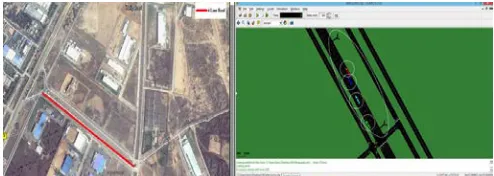
We have used the OSM map of NH-8 Highway of Neemrana, Rajasthan, India and generated the flow of vehicles on the map where we have a four-lane road. Fig. 5.1 shows a part of actual Neemrana map where the four-lane road track is available and we have used it as a test-bed for our hardware.
Fig. 5.1 Actual and SUMO developed map of Neemrana
The mobility model which we have generated using SUMO-MOVE will be simulated in NS-2 with the help of the .sumo.tr and .tcl [13] files. The simulation result of the algorithm discussed above can be seen in the figure below (Fig. 5.2). In NS-2 the nodes -> 1,2,3,4 are the 4 vehicles on 4 different tracks that were generated by using the SUMO software. The algorithm is implemented in NS-2 for showing the concept of lane changing based on the speed of the vehicles and the minimum gap being maintained in between the vehicles.
In Fig. 5.2 the NS-2 simulation shows the vehicle no. 2 shifts its lane based on the speed change. Initially it starts from the first lane and then shifts to the third lane based on the speed based lane-changing algorithm. The mingap
estimation based lane changing is also shown in Fig. 5.2.
Fig. 5.2 mingap estimation based lane changing
TABLE I.
PARAMETERS USED IN SIMULATION (NS-2)
Parameter Value (s)
Channel Type Wireless Channel
Antenna Model Omni Antenna
Network Interface Type WirelessPhy Interface Queue Type Droptail
MAC Type Mac/802.11p
Radio Propagation Model TwoRayGround
Ad Hoc Routing Protocol AODV/GPSR
Further, we have also made a comparison using two different protocols Ad-Hoc On-Demand Distance Vector (AODV) and Greedy Perimeter Stateless Routing Protocol (GPSR). We have taken two parameters into consideration- the average end-to-end delay and the packet loss ratio. Two scenarios i.e., varying number and speed of vehicles have been taken into consideration for exchange of information and better quality of service (QoS) of the system.
Scenario 1: In this scenario the number of vehicles is varied and the comparison graphs for AODV and GPSR are obtained taking the two parameters into consideration.
Fig. 6.1.1 Average E2E Delay (Number of vehicles)
Fig. 6.1.2 Packet Loss Ratio (Number of vehicles)
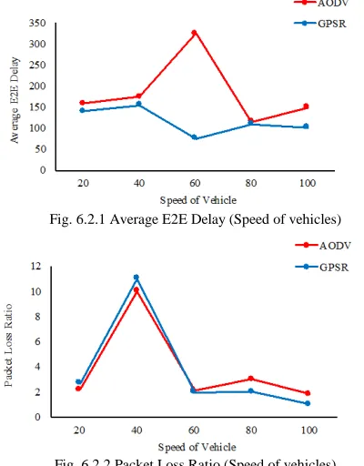
Scenario 2: In this scenario the speed of the vehicles is varied and the comparison graphs for AODV and GPSR are obtained taking the two parameters into consideration.
Fig. 6.2.1 Average E2E Delay (Speed of vehicles)
Fig. 6.2.2 Packet Loss Ratio (Speed of vehicles)
With the help of these graphs we can see that GPSR is more efficient than AODV in terms of efficient packet transmission and average end-to-end delay.
VI. CONCLUSIONANDFUTUREWORK
The proposed system is mainly designed in order to avoid accidents and to alert the drivers about the speed limits for safe navigation. An effective solution is provided to develop the intelligent vehicle, which will operate on safest speed by getting the lane changing [13] assistance from the proposed system. The navigation parameters are monitored in real scenario and suitable emergency messages are sent. Controlling the vehicle speed automatically in real time is very difficult. So, in order to avoid this difficulty, instead of controlling the vehicle speed automatically, this research paper succeeded in alerting the driver about the speed limits and detecting the critical situation. We used the GPSR communication protocol to forward the emergency warnings and messages as we see that the GPSR protocol offers a better packet transmission rate and a comparatively efficient average end to end delay when compared with the AODV routing protocol. The speed-based lane-changing algorithm will play a very important role in VANET and will create a semi-automatic environment, in the concept of smart transportation. The drivers will get full and authentic information of their surrounding without much effort. In this paper, we have explained the protocol and the first level implementation of the algorithm with the help of SUMO-MOVE, NS-2 and some field trials with the hardware prototype. Further, we will use different packet forwarding strategies for different connection states [10]. As we are transmitting information like the location, speed etc. from the hardware, there may be a case where the data can be manipulated. We will improve our protocol in such a way that it takes care of this issue.
REFERENCES
[1] “Vehicular ad hoc networks”, wikipedia.org, 2015. [online], Available: http://en.wikipedia.org/wiki/Vehicular_ad_hoc_ network.
[2] C. F. Chiasserini, E. Fasolo, R. Furiato, R. Gaeta, M. Garetto, M. Gribaudo, M. Sereno, A. Zanella, “Smart Broadcast of Warning Messages in Vehicular Ad Hoc Networks” in Workshop Interno Progetto NEWCOM (NoE), 2005.
[3] R. P. Nayak, “High Speed Vehicle Detection in Vehicular Ad-hoc Network”, M.S. thesis, Dept. of Computer Science and Engineering, National Institute of Technology Rourkela, India, May 2013.
[4] N. Kassem, A. E. Kosba and M. Youssef, “RF-based Vehicle Detection and Speed Estimation”, Vehicular Technology Conference (VTC Spring), 2012 IEEE 75th, pp. 1-5, IEEE, 2012.
[5] R. S. Raw, M. Kumar, N. Singh, “Security Challenges, Issues, and their Solutions for VANET”, International Journal of Network Security and its Applications (IJNSA), 5 (5), 2013. [6] R. Rubini and U. A. Makeswari, “Over Speed Violation
Management of a Vehicle Through Zigbee”, International Journal of Engineering Science and Technology, 5(1), pp. 340, Feb-March 2013.
[7] S. P. Bhumkar, V. V. Deotare, R. V. Babar “Accident avoidance and detection on highways”, InternationalJournal of Engineering Trends and Technology, 3 (2), ISSN: 2231-5381, 2012.
[8] “GPS – NMEA sentence information”, Aprs.gids.nl, 2015. [online] Available: http://aprs.gids.nl/nmea/#gll
ISSN: 1942-9703 / © 2016 IIJ VANET”, Vehicular Technology, IEEE Transactions, 61 (1),
pp. 275-285, 2012.
[10] Z. He, J. Cao and T. Li, “MICE: A Real-time Traffic Estimation Based Vehicular Path Planning Solution using VANETs”, Connected Vehicles and Expo (ICCVE), 2012 International Conference on IEEE, pp. 172-178, IEEE, 2012. [11] “Using Network Simulator-2”, nsnam.isi.edu, 2015. [online],
Available: http://nsnam.isi.edu/nsnam/index.php/Main_Page [12] F. J. Martinez, C. K. Toh, J. C. Cano, C. T. Calafate and P.
Manzoni, “A Survey and Comparative Study of Simulators for Vehicular Ad hoc Networks (VANET’s)”, Wireless
Communication and Mobile Computing, DOI: 10.1002/wcm.859, 2009.
[13] S. Tan and J. Mae, “Real-Time Lane Recognition and Position Estimation for Small Vehicle”, Internetworking Indonesia Journal, 5 (2), 2013.
Yash Agarwal is currently pursuing a Bachelor degree in Electronics and Communications Engineering at NIIT University in India. His research interests include connected vehicles, vehicular communications and embedded systems. He started his research work in vehicular networks and real time systems in May 2014 and has been working in the same field since then. He is a student member in the Institute of Electrical and Electronics Engineers (IEEE) and Computer Society of India(CSI) since January 2015.
Kritika Jain is currently pursuing a Bachelor degree in Electronics and Communications Engineering at NIIT University in India. Her research interests include vehicular communications, real time systems and localization techniques.