TECHNICAL NOTE
TRAJECTORY TRACKING OF A MOBILE ROBOT USING
FUZZY LOGIC TUNED BY GENETIC ALGORITHM
H. N. Pishkenari, S. H. Mahboobi and A. Alasty*
Center of Excellence in Design, Robotics and Automation (CEDRA) Department of Mechanical Engineering, Sharif University of Technology
Tehran, Iran, Tel: +98216165504, Fax: +98216000021 [email protected]
* Corresponding Author
(Received: February 6, 2004 – Accepted in Revised Form: August 9, 2006)
Abstract In recent years, soft computing methods, like fuzzy logic and neural networks have been presented and developed for the purpose of mobile robot trajectory tracking. In this paper we will present a fuzzy approach to the problem of mobile robot path tracking for the CEDRA rescue robot with a complicated kinematical model. After designing the fuzzy tracking controller, the membership functions and rule weights will be optimized by genetic algorithm in order to obtain more acceptable results. Simulation results have demonstrated significant improvements in controller efficacy.
Key Words Fuzzy Control, Trajectory Tracking, Rescue Robot, Genetic Algorithm
ﭼ
ﺪﻴﻜ
ﻩ
ﻱﺍﺮﺑﻲﻳﺎﻬﺷﻭﺭﻥﺍﻮﻨﻋﻪﺑﻲﺼﻋﻱﺎﻫﻪﮑﺒﺷ ﻭﻱﺯﺎﻓﻖﻄﻨﻣﺪﻨﻧﺎﻣ ﺪﻨﻤﺷﻮﻫﻱﺎﻬﻤﺘﺴﻴﺳﺮﻴﺧﺍ ﻱﺎﻬﻟﺎﺳﺭﺩ
ﺭﺩﺮﻴﺴﻣﺐﻴﻘﻌﺗﻑﺪﻫ ﻪﺘﻓﺎﻳﻪﻌﺳﻮﺗﺭﺎﻴﺳﻱﺎﻬﺗﺎﺑﺭ
ﻭ ﻩﺪﺷﻪﺋﺍﺭﺍ ﺪﻧﺍ
.
ﻱﺯﺎﻓﻖﻄﻨﻣﺮﺑ ﻲﻨﺘﺒﻣﻲﺘﻓﺎﻴﻫﺭﺮﺿﺎﺣﻪﻟﺎﻘﻣﺭﺩ
ﺮﮔﺩﺍﺪﻣﺍﺕﺎﺑﺭﺮﻴﺴﻣﺐﻴﻘﻌﺗﻪﻟﺎﺴﻣﻱﺍﺮﺑ
"
ﺍﺭﺪﺳ
"
ﻲﻣﻱﺍﻩﺪﻴﭽﻴﭘﻲﮑﻴﺗﺎﻤﻨﻴﺳﻝﺪﻣﻱﺍﺭﺍﺩﻪﮐ ﺖﺳﺍ ﻩﺪﺷﻪﺋﺍﺭﺍ،ﺪﺷﺎﺑ
.
ﺩﻑﺪﻫ ﺎﺑﻱﺯﺎﻓﻦﻴﻧﺍﻮﻗ ﻱﺭﺍﺬﮕﺷﺯﺭﺍﻭﺖﻳﻮﻀﻋﻊﺑﺍﻮﺗ،ﻱﺯﺎﻓ ﻝﺮﺘﻨﮐﻢﺘﺴﻴﺳﻲﺣﺍﺮﻃﺯﺍﺲﭘ ،ﺮﺘﻬﺑﺞﻳﺎﺘﻧﻪﺑﻲﺑﺎﻴﺘﺳ
ﺪﻧﺍﻩﺪﺷﻪﻨﻴﻬﺑ
.
ﺖﺳﺍﻩﺩﺍﺩﻥﺎﺸﻧﻲﻟﺮﺘﻨﮐﻢﺘﺴﻴﺳﻲﻳﺍﺭﺎﮐﺭﺩﺍﺭﻱﺯﺭﺎﺑﺩﻮﺒﻬﺑﻱﺯﺎﺳﻪﻴﺒﺷﺞﻳﺎﺘﻧ
.
1. INTRODUCTION
The problem of trajectory tracking for mobile robots has been an attractive issue in the robotic field during recent years. Our purpose is to control a certain high mobility rover for rescue operations that have has a complex kinematical model.
Path tracking has been widely investigated, such as, Dongbing Gu and Huosheng Hu [1] who developed a path tracking scheme for a car-like mobile robot based on neural predictive control; Jacky Baltes and Robin Otte [2] developed a Fuzzy Logic Path Controller for path tracking, Jiri Sika and Joop Pauwelussen [3] used Look-ahead Virtual Point and developed a lateral controller to follow a pre-described path.
Waneck [4] proposed a fuzzy controller for an autonomous boat in absence of a nonlinear
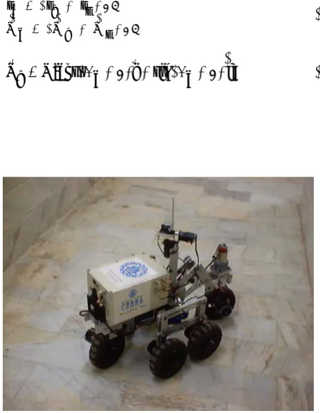
Figure 1. Cedra Rescue Robot.
y
x
θ
θ
L
f
r
Fc
(xc , yc) Instantaneous Center
of Rotation
Figure 2. Kinematic Model of the Robot.
Some researchers have studied genetic algorithms for context adaptation [8]. Others have used genetic algorithms to design the rule base and the scale factors when the normalized membership functions are fixed [9]. Some studies used neural networks for context adaptation [10]. A genetic learning process for the membership function design, coupled with a heuristic method for the rule base design, has been proposed in [11].
The subject of this paper is restricted to the tuning of membership functions. Researchers have used many different methods over the past decade to optimize fuzzy membership functions. These methods include genetic algorithms [12], neural networks [13], evolutionary programming [14], geometric methods [15], fuzzy equivalence relations [16], heuristic methods [17], and gradient descent [18].
Design and selection of linguistic variables and rules of a fuzzy controller require expert knowledge of the under control system. This knowledge is usually obtained by trial-and-error or by consulting and observing a human operator controlling a real system.
One of the main factors in the design of efficient and robust fuzzy logic controllers is the selection of parameters of the membership functions. We intended to have a weight to every rule and optimize these weights for finding suitable rule base. The existing approaches for choosing the membership functions are based on trial-and-error process, which mostly lack learning and autonomy. One method of removing the uncertainty associated with the selection of these variables is the use of genetic algorithms (GA). In this trajectory tracking application, the fitness function evaluates the robot’s path, taking into account the distance and orientation error from the desired path. The optimum membership functions and weights of the rules differ from one path to another. Therefore a very complicated desired path has been chosen in the optimization process, to assure the robustness of the optimal fuzzy controller.
2. KINEMATIC MODEL OF THE ROBOT
A top view of CEDRA rescue robot (see Figure 1.)
is shown in Figure 2. This mobile robot consists of six wheels. Front and rear ones are steerable and the remaining four wheels are mounted beside the robot. Robot kinematic Equations derivation can be seen in the Equation 1 through 8 and Equations 9, 10 and 11 depict the final relations.
2 / ) r V f V ( c V
2 / ) r r f r ( c r
r r r
r r r
+ =
+ =
(1)
] j ) c sin( i ) c [cos( V f
Fc
x
y d
(xc , yc) (xn , yn , Fn)
)
DF
Figure 3. Robot And Path Curve Interaction.
] j ) c sin( i ) c [cos( V r
Vr = φ −θ r+ φ −θ r (3)
] j 2 ) c ( sin ) c ( sin i 2 ) c ( cos ) c ( cos [ V c V r r r θ − φ + θ + φ + θ − φ + θ + φ = (4) ] j ) c sin( i ) c [cos( cos . V c
Vr = θ φ r+ φ r (5)
c sin cos . V c y c cos cos . V c x φ θ = φ θ = & & (6) c c
c ) sin( ) 2sin .cos
(
sin φ +θ − φ −θ = θ φ (7)
c c
c cos 2V.sin . cos
L φ& φ = θ φ (8)
t ). ) t ( c ( cos ). ) t ( ( cos . ) t ( V ) t ( c x ) t t ( c x Δ φ θ + = Δ + (9) t ). ) t ( c ( sin . ) ) t ( ( cos ). t ( V ) t ( c y ) t t ( c y Δ φ θ + = Δ + (10) t ). ) t ( ( sin L ) t ( V 2 ) t ( c ) t t (
c +Δ =φ + θ Δ
φ (11)
Interaction between robot and path curve is shown in Figure 3. Xc and Yc give the coordinates of the robot geometrical center. The orientation of the robot is given by Φc. Coordinates Xn and Yn are the coordinates of the closest point to the robot on the path. The slope of the path at this point is given by
Φn. In addition, subscripts r, c and f refer to the rear, center and front of the robot respectively. In this application, the control signals are robot velocity and steering angle, which are determined based on the deviation between the desired and actual position and orientation. It should be mentioned that environment is completely known and path is prescribed and then the optimized fuzzy controller will be proposed for tracking this path. The control function is defined as a function of positional error (d), the orientation error (ΔΦ), and the curvature of the path (R). The positional error is the distance between points (Xc, Yc) and (Xn, Yn ). The orientation error is defined as ΔΦ = Φn - Φc. It is assumed that the path is continuous. However,
the curvature and any derivative of the path may be discontinuous.
3. DESIGN OF THE FUZZY LOGIC CONTROLLER
The crux of designing an FLC lies in the selection of high-performance membership functions that represent the human expert’s interpretation of linguistic variables, because different membership functions determine the extent to which the rules affect the action and hence the performance [19]. The existing iterative approaches for choosing the membership functions are basically a manual trial-and-error process and lack learning capability or autonomy. Therefore, the more efficient and systematic genetic algorithm which acts on the survival-of-the-fittest has applied to FLC design for searching the poorly understood, irregular and complex membership function space with improved performance.
⎪ ⎪ ⎪ ⎪ ⎩ ⎪ ⎪ ⎪ ⎪ ⎨ ⎧ ∞ ∈ ∈ − − ∈ ∈ − − ∞ ∈ = μ ) , d [ x , 0 ) d , c [ x , c d x d ) c , b [ x , 1 ) b , a [ x , a b a x ] a , ( x , 0 ) d , c , b , a ; x (
A (12)
3.1. Fuzzy Input Sets
Fuzzy Logic controller, the input to the controller (curvature, position error, and orientation error) is converted into a series of fuzzy sets via the singleton fuzzifier. The number and exact shape of these fuzzy sets critically determine the performance of the controller. These fuzzy sets describe a qualitative situation in which the output of the controller is qualitatively different.In other words, whenever the desired behavior (e.g., change from going straight to turning left or change from fast to medium speed) of the controller changes in an input situation, a fuzzy set is created to represent this case.
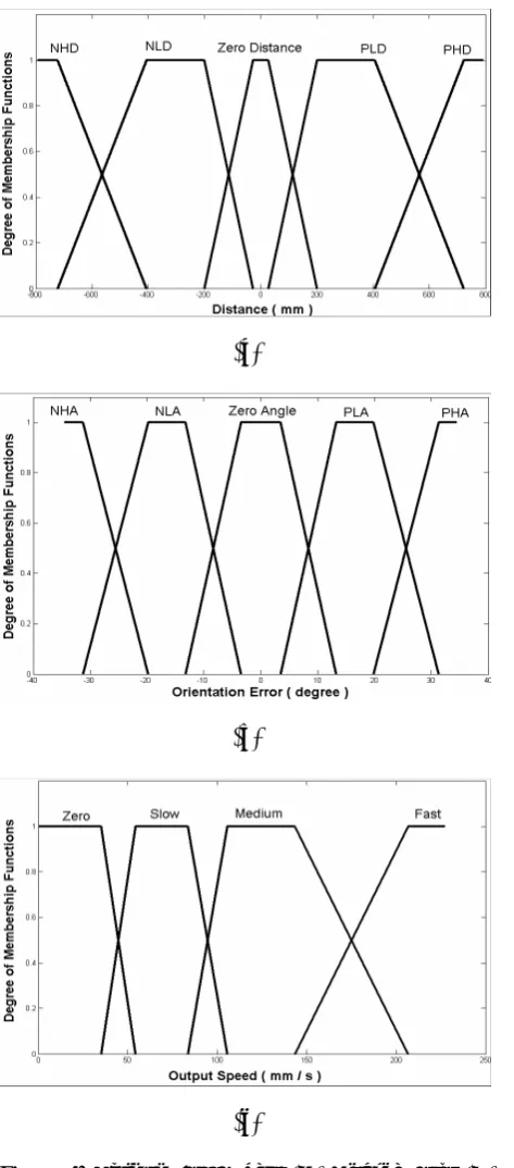
Curvature consists of three fuzzy sets; Left Curvature, Straight and Right Curvature. The fuzzification of the positional error includes five sets; NegHighDist (NHD), NegLowDist (NLD), ZeroDist (ZD), PosLowDist (PLD) and PosHighDist (PHD). Clearly it is desirable that the robot be on the line (ZeroDist). Assume that the robot is far away from the path, then the desired behavior is to turn either right/left towards the path, drive straight towards the path, and turn left/right to straighten out. Therefore, we require two extra sets on each side of the path.
Similar reasoning leads to the design of the fuzzy sets for the orientation error. A total of five sets have been used to describe different cases; NegHighAngle (NHA), NegLowAngle (NLA), ZeroAngle (ZA), PosLowAngle (PLA) and PosHighAngle (PHA).
3.2. Fuzzy Output Sets
There are two outputs from fuzzy controller to the robot: (a) speed and (b) Steering Angle. There are four membership functions for describing the speed heuristic variable: Zero, Slow, Medium and Fast. The steering Angle is determined by using five membership functions; SharpLeft (SL), LowLeft (LL), Stright (ST), LowRight (LR) and SharpRight(SR). A crisp output value is then computed from this fuzzy set. In this research, we used the well-known centroid defuzzification method, which uses the center of gravity as the crisp output value.
3.3. Fuzzy Rule Base
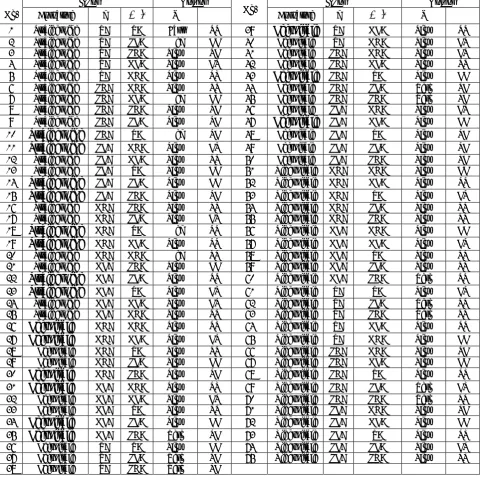
Given these fuzzy input sets, a fuzzy controller uses a set of fuzzy rules to specify the desired control behavior through the minimum inference engine. After the design of the fuzzy input and output sets, the design of the fuzzy rules is straight forward. There are a total of 5*5*3=75 possible different input configurations. For each of these input configurations, a rule was specified to indicate the desired speed and directional settings. The controller rule base appears in Table 1.4. GENETIC ALGORITHM
Algorithms for function optimization are generally limited to convex regular functions. However, many functions are multi-model, discontinuous, and non-differentiable. Genetic algorithms (GAs) are a class of stochastic search techniques, loosely based on ideas from biological evolution, which have been used successfully for a great variety of different problems (e.g., [21-23]).
The GA searches for an optimal solution from a population of candidate solutions according to an objective function, which is used to establish the fitness of each candidate as a solution. The governing process in the search is the application of appropriate breeding operators to candidate solutions in a given generation to form the candidates for the next generation. These operators are designed to preserve the most successful aspects of candidate fitness until the best possible solution is attained.
TABLE 1. Fuzzy Rule Base.
Input Output Input Output
No. Curvature d
Δ
φ
V Θ No. Curvature dΔ
φ
V Θ 1 StraightLine ZD ZA Fast ST 39 LeftCircle ZD NLA Slow ST 2 StraightLine ZD PLA Med LL 40 LeftCircle ZD NHA Slow LR 3 StraightLine ZD PHA Slow SL 41 LeftCircle PHD NHA Slow LR 4 StraightLine ZD NLA Slow LR 42 LeftCircle PHD NLA Slow ST 5 StraightLine ZD NHA Slow SR 43 LeftCircle PHD ZA Slow LL 6 StraightLine PHD NHA Slow ST 44 LeftCircle PHD PLA Zero SL 7 StraightLine PHD NLA Med LL 45 LeftCircle PHD PHA Zero SL 8 StraightLine PHD PHA Slow SL 46 LeftCircle PLD NHA Slow LR 9 StraightLine PHD PLA Slow SL 47 LeftCircle PLD NLA Slow LL 10 StraightLine PHD ZA Med SL 48 LeftCircle PLD ZA Slow SL 11 StraightLine PLD NHA Slow LR 49 LeftCircle PLD PLA Slow SL 12 StraightLine PLD NLA Slow ST 50 LeftCircle PLD PHA Slow SL 13 StraightLine PLD ZA Slow LL 51 RightCircle NHD NHA Slow LL 14 StraightLine PLD PLA Slow LL 52 RightCircle NHD NLA Slow ST 15 StraightLine PLD PHA Slow SL 53 RightCircle NHD ZA Slow LR 16 StraightLine NHD PHA Slow ST 54 RightCircle NHD PLA Slow SR 17 StraightLine NHD PLA Slow LR 55 RightCircle NHD PHA Slow SR 18 StraightLine NHD ZA Med SR 56 RightCircle NLD NHA Slow LL 19 StraightLine NHD NLA Slow SR 57 RightCircle NLD NLA Slow LR 20 StraightLine NHD NHA Med SR 58 RightCircle NLD ZA Slow SR 21 StraightLine NLD PHA Slow LL 59 RightCircle NLD PLA Slow SR 22 StraightLine NLD PLA Slow ST 60 RightCircle NLD PHA Zero SR23 StraightLine NLD ZA Slow LR 61 RightCircle ZD ZA Slow LR
24 StraightLine NLD NLA Slow LR 62 RightCircle ZD PLA Zero SR 25 StraightLine NLD NHA Slow SR 63 RightCircle ZD PHA Zero SR 26 LeftCircle NHD NHA Slow SR 64 RightCircle ZD NLA Slow ST 27 LeftCircle NHD NLA Slow LR 65 RightCircle ZD NHA Slow LL 28 LeftCircle NHD ZA Slow ST 66 RightCircle PHD NHA Slow SL 29 LeftCircle NHD PLA Slow LL 67 RightCircle PHD NLA Slow LL 30 LeftCircle NHD PHA Slow SL 68 RightCircle PHD ZA Slow ST 31 LeftCircle NLD NHA Slow SR 69 RightCircle PHD PLA Zero LR 32 LeftCircle NLD NLA Slow LR 70 RightCircle PHD PHA Zero SR 33 LeftCircle NLD ZA Slow ST 71 RightCircle PLD NHA Slow SL 34 LeftCircle NLD PLA Slow LL 72 RightCircle PLD NLA Slow LL 35 LeftCircle NLD PHA Zero SL 73 RightCircle PLD ZA Slow ST 36 LeftCircle ZD ZA Slow LL 74 RightCircle PLD PLA Slow LR 37 LeftCircle ZD PLA Zero SL 75 RightCircle PLD PHA Slow SR 38 LeftCircle ZD PHA Zero SL
Individuals or current approximation, are encoded as strings, chromosomes, composed over some alphabet, so that the genotypes (chromosome values) are uniquely mapped onto the decision variable (phenotypic) domain.
while in mutation a randomly generated bit position is altered to a new value. For each function, the user must define a probability that indicates the effect of that function in the evolution. In each section a random number is needed for use in the algorithm. The evolution is based on the statistical nature of these numbers and functions [24].
The following pseudocode gives an abstract view of genetic algorithm.
begin GA
g: = 0 { generation counter } Initialize population P (g) Evaluate population P (g) while not done do
g: = g+1
Select P(g) from P (g-1) Crossover P(g)
Mutate P (g) Evaluate P (g) end while
end GA
5. MEMBRESHIP FUNCTION AND WEIGHT OPTIMIZATION
THROUGH GA
From the viewpoint of a genetic search the membership functions and weight of the rules can be seen as functions, the parameters of which are necessary to achieve optimization in general terms and independently of sensory application. The goal is to achieve the minimum distance and time in path tracking. Since some rules may be uncertain, the weight of the rules is optimized too. The range of membership function parameters is determined based on robot and path dimensions. Here the range defined for weights is [0. 7, 1]. The objective function in mathematical formulation as applied to this work is:
If penalty function is met
( )
i factor time Distancefactor
obfun imax 2
1 i
1× + ×
=
∑
=
(13)
Else obfun =1020 (14) Where penalty function is failed if (max (Distance
(i)) > Dmax) or (time > Tmax).
The selected values for crossover probability and mutation are 0.9 and 14/ Lind, respectively. We have assumed that the number of generations or analyzed cycles of populations is 1000 and at first in every generation all the individuals are substituted to the next generation. The result of GA optimization for some membership functions have been shown in Figure 4.
6. SIMULATION RESULTS
Simulations are presented using a complicated desired path including several break points to show the controller performance. Figures 5 and 6 show the response of initial and optimized FLC, respectively. As can be seen, the deviation from the desired path has been extremely reduced. In next stage, some noise and delay have been added to the controller inputs and outputs in order to simulate the practical conditions in a better manner. So it is better to concern criteria seen frequently in experimental works. At any instant, the position and orientation of robot could be determined by accelerometer and tilt sensor. The amount of uncertainty in input data is in an order of 3cm for position, 5cm/s for speed and 1 degree for orientation and in the form of white noise. Sampling time is considered to be 0.1s. Simulation has been repeated considering noise on input and output signals and the result is shown in Figure 7. Finally Figure 8 illustrates the result of adding a 0.5s transport delay to the disturbances mentioned above. As mentioned earlier, the controller response has been optimized for a certain path. Because of the complexity and variety of curve sections, it is expected that the controller shows an acceptable behavior in case of any arbitrary trajectory. In order to illustrate this feature, the controller has been tested over a different path and its response is shown in Figure 9.
7. CONCLUDING REMARKS
(a)
(b)
(c)
Figure 4. Optimum Fuzzy Sets: (A) Distance Error (B) Orientation Error And (C) Speed.
rule weights, (to achieve minimum deviation from desired path) we have used Genetic Algorithm
method. Finally for approaching to the real conditions first we exert noise in inputs and outputs of the controller. Then we added transport delay to the controller. According to the simulation results, performance of the optimized controller is acceptable even if noise, disturbance and transport delay are added to the system. Also the controller performance remains acceptable in spite of changing the desired path.
8. REFERENCES
1. Gu, D. and Hu, H., "Neural Predictive Control for a Car - like Mobile Robot", Int. Journal of Robotics and Autonomous Systems, Vol. 39, (2002), 2-3.
2. Baltes, J. and Otte, R., "A Fuzzy Logic Controller for Car-like Mobile Robots", Int. Symposium on Computation Intelligence in Robotics and Automation, Monterrey, (1999).
3. Sika, J. and Pauwelussen, J., "Entering of Automated Platoon", Int. Symposium on Advanced Vehicle Control, Japan, (2002).
4. Waneck, T. W., "Fuzzy guidance controller for an autonomous boat", Proceedings of the IEEE Control and Systems, Vol. 17, No. 2, (1997).
5. Sugeno, M. and Murakami, M., "An experimental study and fuzzy parking control using a model car", Proceedings of the Industrial Applications of Fuzzy Control, North-Holland, Amsterdam, (1985), 125–128. 6. Larkin, L. I., "A fuzzy logic controller for aircraft flight
control", Proceedings of the Industrial Applications of Fuzzy Control, North-Holland, Amsterdam, (1985), 87– 107.
7. Cordon, O., Herrera, F. and Villar, P., "Analysis and Guidelines to Obtain a Good Uniform Fuzzy Partition Granularity for Fuzzy Rule-Based Systems Using Simulated Annealing", International Journal of Approximate Reasoning,25, (2000), 187-216.
8. Gudwin, R., Gomide, F. and Pedrycz, W., "Context Adaptation in Fuzzy Processing and Genetic Algorithms", International Journal of Intelligent Systems 13, (1998), 929-948.
9. Magdalena, L., "Adapting the Gain of an FLC with Genetic Algorithms", International Journal of Approximate Reasoning 17, (1997), 327-349.
10. Pedrycz, W., Gudwin, R. and Gomide, F., "Nonlinear Context Adaptation in the Calibration of Fuzzy Sets", Fuzzy Sets and Systems 88, (1997), 91-97.
11. Cordon, O., Herrera, F., Magdalena, L. and Villar, P., "A Genetic Learning Process for the Scaling Factors, Granularity and Contexts of the Fuzzy Rule-Based System Data Base", Information Sciences, 136, (2001), 85-107.
Figure 5. Robot Path Tracking Before Optimization.
Figure 6. Robot Path Tracking after Optimization.
13. Barada, W. and Singh, H., "Generating Optimal Adaptive Fuzzy-Neural Models of Dynamical Systems with Applications to Control", IEEE Transactions on Systems, Man, and Cybernetics, Part C 28, (1998), 371-391.
14. Goddard, J., Parrazales, R., Lopez, I. and de Luca, A., "Rule Learning in Fuzzy Systems Using Evolutionary Programs", IEEE Midwest Symposium on Circuits and Systems, Ames, Iowa, (1996), 703-709.
15. Smith, S. and Comer, D., "Automated Calibration of a Fuzzy Logic Controller Using a Cell State Space Algorithm", IEEE Control Systems Magazine, Vol. 11, No. 5, (1991), 18-28.
16. Wu, R. and Chen, S., "A New Method for Constructing Membership Functions and Fuzzy Rules from Training Examples", IEEE Transactions on Systems, Man and Cybernetics, (1999), 25-40.
17. Tao, C. and Taur, J., "Design of Fuzzy Controllers with
Adaptive Rule Insertion", IEEE Transactions on Systems, Man, and Cybernetics, Part B: Cybernetics 29, (1999), 389-397.
18. Demaya, B., Palm, R., Boverie, S. and Titli, A., "Multilevel Qualitative and Numerical Optimization of Fuzzy Controller", IEEE International Conference onFuzzy Systems, Yokohama, Japan, (1995), 1149-1154.
19. Kim, C. N. and Yun, L., "Design of Sophisticated Fuzzy Logic Controllers Using Genetic Algorithms, Dept. of Electronics and Electrical Eng.", Proc. 3rd IEEE Int. Conf. On Fuzzy Systems, Orlando, FL, Vol. 3, (1994), 1708-1712.
20. Wang, L., X., Course, A., “Fuzzy Systems and Control”, Prentice-Hall Int., Englewood Cliffs, NJ, (1997). 21. De Jong, K. A., “Analysis of the behavior of a class of
Figure 7. Robot Path Tracking After Optimization With Noise In Input & In Output Of FLC.
Figure 8. Robot Path Tracking After Optimization With Noise In Input & In Output Of Flc With Considering Transport Delay.
22. Goldberg, D. E. and Samtani, M. P., "Engineering optimization via genetic algorithm", 9th Conference on Electronic Computations, New York, USA, (1986), 471-482. 23. Grefenstette, J. J. and Fitzpatrick, J. M., "Genetic search
with approximate function evaluation", International
Conference on Genetic Algorithms and Their Applications, Pittsburgh, USA, (1985), 112-120. 24. Goldberg, D. E., "Genetic Algorithms in Search,