Please cite this article as: M. Yuan, Field Programmable Gate Array Implementation of Active Control Laws for Multi-mode Vibration Damping, International Journal of Engineering (IJE), TRANSACTIONS B: Applications Vol. 29, No. 2, (February 2016) 229-235
International Journal of Engineering
J o u r n a l H o m e p a g e : w w w . i j e . i rField Programmable Gate Array Implementation of Active Control Laws for
Multi-mode Vibration Damping
M. Yuan*
College of Automation, Nanjing University of Posts and Telecommunications, Nanjing, China
P A P E R I N F O
Paper history:
Received 24 November 2015
Received in revised form 20 January 2016 Accepted 26 January 2016
Keywords:
FPGA Control
Multi-mode Vibration Control Real-time FPGA Target Smart Structure Plate
A B S T R A C T
This paper investigates the possibility and effectiveness of multi-mode vibration control of a plate through real-time FPGA (Field Programmable Gate Array) implementation. This type of embedded system offers true parallel and high throughput computation abilities. The control object is an aluminum panel, clamped to a Perspex box’s upper side. Two types of control laws are studied. The first belongs to non-model based control. This control law is designed to generate active damping within the designed bandwidth. The second control law is model based H-infinity robust control. A system identification process is needed before the controller comes out. Each of the control laws is implemented on a FPGA target, which is powerful enough to achieve high throughput control loop rates. The experimental control results demonstrate that the non-model based control law has sufficient authority to suppress the interesting modes. The model-based robust control law’s control performance is not so positive compared to the previous method. Therefore, it is not recommended for this application.
doi: 10.5829/idosi.ije.2016.29.02b.12
1. INTRODUCTION1
Multi-mode vibration control of plate structures has numerous potential applications for automobiles, aircraft cabins and satellite solar array panels, etc. The vibration behavior of these structures under various mechanical disturbances are characterized by multiple resonances within the excitation spectrum. Vibration resonances are harmful to the structure, which may induce excessive noise and reduce the service life. As piezoelectric material has the ability to behave as sensor and actuator, and can be easily integrated within the structure [1]. This technology has great value for such applications [1].
The sensor and actuator can be placed on, or embedded into the structure, and the structure’s dynamic properties can be sensed or changed through the properly designed controller. With respect to multi-mode vibration control application, the most effective
11*Corresponding Author’s Email: [email protected] (M.
Yuan)
guarantee the desired control rate. Concerning the hardware, recently, the development of modern Field-Programmable Gate Array (FPGA) technology provides a new way of rapid control prototyping. Hardware timing and reconfigurable properties imply that it is flexible and true parallel in nature [9]. The real-time property guarantees that the control law can be
implemented within specific time intervals
determinately with nano-second scale of jitter. Also, the power consumption is very low. These advantages are very attractive for engineering applications. Accordingly, FPGA platform is chosen as the real-time device in the following active vibration control experiments. In view of active control laws, two types of controllers are needed to be compared, one is non-model based, the other a non-model-based controller. The major difference between the two types of controllers lies on whether the system identification process is needed or not. In addition, little research work has been done about comparing the two types of controller applied to multi-mode vibration control of a plate. In this study, two control laws are synthesized and demonstrated for multi-mode vibration control: one belongs to non-model based control, and the other is model based robust control. Each of the control laws has the capability of puttingthe control authorities within a certain frequency band. Therefore, it is interesting to compare them with respect to this application. Each controller is deployed on a Xilinx Virtex-5 LX110 FPGA platform, which is powerful enough to achieve high control rates throughput due to its physical parallemechanism.
In Section 2, the experimental system is set up and control plant’s dynamic property is described. In Section 3, a novel non-model based controller is proposed and the active control experimental results demonstrate that the FPGA target is suitable for the active vibration control application. In Section 4, the robust H-infinity controller is designed and the active control is implemented and compared with the previous algorithm. The final conclusion section gives some comments concerning the two control laws and gives the authors’ recommendation.
2. CONTROL PLANT DESCRIPTION AND
EXPERIMENTAL SYSTEM SETUP
The control plant is an aluminum plate, which is fixed by a frame and is mounted on a Plexiglas box. Inside the cavity, a loudspeaker is driven by an audio power amplifier to generate stochastic acoustic excitation to the plate (see Figure 1). Before active control starts, an experimental modal analysis test is carried out to obtain a clear view of the plate’s dynamic properties. For the test, 169 measurement points are distributed evenly on the plate, which is shown in Figure 2.
Figure 1. Test structure to be investigated
Figure 2. Mesh points for experimental modal analysis
For a vibration system, the response between a moving impact hammer and a fixed point can be expressed using the modal superposition method [10]:
(1)
where , and are modal mass, modal stiffness and modal damping of the test structure, respectively.
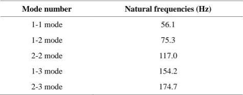
These FRF responses can be obtained and analyzed with the help of NI 9234 DAQ card and M+P So Analyzer modal software. The identified first five modal frequencies and the mode number information are summarized in Table 1.
TABLE 1. Mode number and natural frequencies of the test structure
Mode number Natural frequencies (Hz)
1-1 mode 56.1
1-2 mode 75.3
2-2 mode 117.0
1-3 mode 154.2
2-3 mode 174.7
T
2 1
( ) ( )
n
i i
i i i i
F x
M j C K
i
In the low frequencies, the acoustic wavelength can be expressed as:
(2)
where c and f are the acoustic wave propagation speed and the frequency, respectively. Since the acoustic wavelength is much larger than the plate’s dimension, this type of excitation can be approximately considered as plane wave excitation in the low frequencies. Therefore, the 1-1 mode and 1-3 mode can be excited effectively by the loudspeaker, and thus become the main interesting modes concerning vibration control. A piezoelectric actuator is bonded at the center of the plate. With a properly designed control law, it can exert sufficient control authority to these modes.
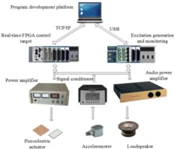
The schematic diagram of the experimental system is shown in Figure 3. An accelerometer (PCB 352A56, 1.8 gram) placed at the center of plate and conditioned by a B&K 2693 signal conditioner is used to sense the vibration. The acceleration sensing has been wildly used in the structure dynamics, the signal is acquired by the NI-9215 DAQ card and is sent into NI CRIO FPGA controller. A piezo power amplifier links the controller’s analog output NI-9263 DAQ card and the piezoelectric actuator. Besides the real-time control system, a Windows based cDAQ-9178 system is used to generate stochastic excitation for acoustic excitation and monitoring.
Figure 3.Schematic diagram of the experimental system
Figure 4.Bode plot of the controller with different damping ratios
3. NON-MODEL BASED FEEDBACK CONTROL
Theoretically, when the sensor and actuator is collocated, the velocity can be fed back directly to the actuator with a constant gain. It generates active damping to the structure. The direct velocity control law [11] can be written as:
(3)
Since this type of control law is a simple gain and does not need the system identification process, it belongs to non-model based control law.
In practice, the sensor and the piezoelectric patch cannot be physically collocated. In addition, phase lag and distortion are existing in the electrical system, which means the control system has limited bandwidth. Also, high frequency disturbances have large influence on the controller’s stability. However, as shown in Equation (3), the constant gain feedback means the controller does not roll off at higher frequencies. Thus, the control law’s gain margin is small and the resulting control may not be satisfying. Here, an improved feedback control law is proposed, which can be written as:
(4)
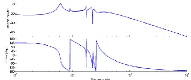
The control law’s bandwidth is set to 500 Hz in this test. The damping ratio mainly influences the amplitude and phase responses. Here, the Bode plots with various are shown in Figure4.
Figure 4 notes that this proposed controller behaves like pure velocity feedback below the cut-off frequency. Moreover, this controller rolls off gradually above the cut-off frequencies, which is a favorable property. The damping ratio influences the controller’s gain and phase transition properties below . In the following experiment, this parameter is set to 0.7, which is a balance of the above issues.
Since the controller does not rely on the structure’s model, it belongs to the non-model based control. After the controller has been synthesized, the Laplace S domain is further transformed into Z domain for
discrete time implementation. The bi-linear
transformation method [12] is selected which has the form of:
(5)
where is the sampling time of the discrete system. It is set to second in this experiment.
The FPGA behaves as a reconfigurable circuit, the connections can be optimized and modified in the development stage. Here, the control logic is developed with the help of graphical LabVIEW FPGA module.
= /c f
H(s) k
2 2
2 (s)
2
n
n n
s H k
s s
n
n
1 / 2
1 / 2
Ts z
Ts
T -5
The data flow programming greatly simplifies the VHDL description, which is favorable for rapid control prototyping. The graphic FPGA code (Figure 5) can be transformed into the VHDL and Bitfile automatically with LabVIEW FPGA module and Xilinx ISE complier. The flowchart is shown in Figure 6.
Figure 5. LabVIEW FPGA code of the controller
Figure 6. Flowchart for the FPGA implementation
Figure 7. Vibration control result in time domain
Figure 8. Vibration control result in frequency domain
Figure 9. Robust controller design for the augmented system
The experimental vibration control results are shown in Figures 7 and 8.
As shown in Figure 8, the plate’s 1-1 mode and 1-3 mode are suppressed by 10 dB and 14 dB, respectively. In addition, many other modes are suppressed remarkably as well. With the help of roll-off property of the controller, little control spill-over is observed.
4. MODEL BASED H-INFINITY FEEDBACK CONTROL
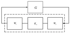
The robust control is the most significant approach with respect to tracking and disturbance application [13-15]. Here, the McFarlance-Glover robust control design method [16] is adopted in this study. The control plant is augmented with a pre and post compensator and to obtain desired loop shaping property (Figure 9). Then, the robust H-infinity algorithm is applied to the augmented model for synthesis, which meets the stability and performance requirement. The synthesized controller is expressed as . The final controller is constructed by multiplying , and together (Figure 10).
(6)
In order to design the controller , the control plant’s model has to be well known. Although the plant model can be synthesized through the FEM (Finite Element Method) model, it usually cannot fit the experimental result very well. Here, the measured frequency response data is utilized by the frequency subspace identification method to identify the control plant.
Figure 10. Synthesized loop shaping robust controller 1
W G W2
K s
G
1
W W2
K
1
W K W2
1 2
K W K W
K
G
K
1
Figure 11.Control plant and identified system model
The robust controller only guarantee to be stable with regard to the identified model, it is usually advisable to include more system dynamics of the control plant. As the actual control plant contains
infinite vibration modes, proper choice should be made between the controller’s order and the system identification bandwidth. In this study, the identification bandwidth is set to 300 Hz.
As the frequency response plot could provide clear insight of the structure’s dynamic properties, it is chosen as the model validation approach during the system identification process. After iterating trials between model refinement and validation, the identified model which best capturing the system’s dynamic properties is adopted. The final measured FRF (Frequency Response Function) curve and the fitted FRF curve are illustrated in Figure 11. The identified model order is 16. The curve fitting result is fairly good at the main resonances.
The identified state space matrixes of A, B, C can be written as follows:
Subsequently, the shaping filter can be applied to the identified model. The pre compensator is designed as a high pass filter to reduce the static and low frequency electrical noise induced by the accelerometer. It is expressed as:
(7)
The post compensator is designed to gradually roll-off and the cut-off frequencies are set to 100 Hz and 400 Hz respectively.
(8)
The final loop shaping controller can be calculated with the help of Matlab robust control command:[K, CL, GAM, INFO]=ncfsyn(G, W1, W2). The final
synthesized controller’s Bode plot is shown in Figure12. This model-based controller performs quite differently from the non-model based controller. This robust controller’s order is high, which means more computational resource is required compared to the previous non-model based type. This SISO controller can be further discretized into:
(9)
The LabVIEW FPGA code is shown in Figure 13, which is further compiled into FPGA Bitfile. The control rates is still set to 20 kHz. Experimental vibration control results for this controller are shown in Figures 14 and 15. The control results indicate the proposed robust control law’s performance is not as effective as the previous method. After active control,
8.14035 1910.08 69.4114 23.5219 37.1745 426.245 395.606 16.8277 254.71 5.83305 98.4486 1.38727 6.87034 0.108596 0.544095 0.0129393 1661.84 1.2427 340.664 80.3937 89.4061 3.63845 1.95241 419.709 0.609381 114.263 0
A
.52527 23.8541 0.0308909 1.57946 0.00218516 0.142299 36.7966 112.714 24.498 1035.5 32.2092 426.255 393.609 48.705 228.115 15.8723 82.6577 3.81073 5.46128 0.289532 0.42039 0.0300342 0.869374 27.4991 1013.98 3.29
016 21.7787 99.6369 91.8056 20.301 52.6344 0.712642 18.6089 1.04492 1.20172 0.144335 0.0911879 0.0173521 3.1128 0.802164 5.84826 4.6031 10.7271 783.066 304.864 64.7141 93.8912 17.3654 38.9653 3.94195 2.90127 0.
285206 0.238819 0.0281994
4.6554 0.518488 21.0264 4.55244 639.579 0.688173 15.1598 923.436 0.211511 229.671 0.817378 52.51 0.0580854 3.77835 0.00428064 0.35971 3.58904 0.602344 12.4006 1.71654 173.333 13.7257 0.99138
2 959.061 0.738751 222.401 0.131246 51.7297 0.0113545 3.77262 0.00223821 0.362006
0.817276 3.99031 0.73882 1.32115 27.6556 590.796 885.763 1.25203 1658.08 3.44469 547.606 0.520463 33.3841 0.0522144 2.44086 0.014
6742
0.594327 0.230707 1.01537 0.928188 1.07144 2.85388 0.853937 110.485 10.4673 200.23 2.53329 337.535 0.27082 21.5762 0.0261952 1.91535 0.336501 0.10955 1.15648 0.491014 3.68606 5.57574 7.09335 1.61613 1219.4
5 8.9115 2057.41 2.18078 98.0465 0.137769 6.32261 0.0340728
0.0863167 0.0296289 0.176627 0.0150831 0.24385 0.535895 0.939961 5.06068 4.58784 474.53 4.35559 1342.69 0.158476 65.7994 0.00588747 5.16283
0.104712 0.04713
78 0.358925 0.201198 1.06927 0.786055 0.511797 0.580253 42.3799 7.08491 1351.29 4.11704 761.714 0.435702 38.829 0.152286 0.00722121 0.0178906 0.0292829 0.0339441 0.0925121 0.0868095 0.0230333 0.154681 5.9438e 5 2
.02794 2.51136 114.551 0.0586112 1748.29 0.255624 102.349
0.0216381 0.00658669 0.0610621 0.0241484 0.168422 0.0755177 0.0176852 0.0856994 1.05316 1.30611 1.50818 1.9144 315.989 5.00232 907.403 2.3416
0.0225593 0.0
181687 0.0751587 0.052386 0.233107 0.195224 0.0947373 0.153106 0.919823 1.65234 2.80298 2.732 0.88998 931.365 3.83842 2036.24 0.0345887 0.0108774 0.112158 0.0525904 0.327782 0.117301 0.0452604 0.159672 1.6926
1.98431 1.76828 2.84884 10.4609 20.1541 932.668 37.3718
4.50001 5.61259 1.68848 4.7331 0.371725 0.408167 0.756034 0.628756 0.538428 0.252714 0.128858 0.0765309 0.0569369 0.0287604 0.0235529 0.00840301 '
B
5 6
9.01932 3.73971 7.36054 0.46829 5.04887 11.171 11.6054 8.27804 3.227 1.04639 0.431083 0.0695691 0.00556598 0.000727806 4.65619 10 5.76694 10
C
1
W
1
12 s W
s
2
W
2
2 100 2 400
2 100 2 400
W
s s
( 1) ( ) ( )
( ) ( ) ( )
n n u n y n n u n
x Ax B
no remarkable reduction can be seen in the time domain. Although there is approximately 6 dB suppression of the 1-3 mode, there is little reduction of the 1st mode.
The robust controller’s experimental result is not satisfying. One possible explanation is as follows: the piezoelectric patch cannot efficiently excite the plate in the low frequency. During the system identification process, the 1st resonance peak is smaller as compared to other vibration modes at high frequencies.
Figure 12. Bode plot of the robust loop shaping controller
Figure 13.LabVIEW FPGA code
Figure 14. Vibration control result in time domain
Figure 15. Vibration control result in frequency domain
This means the signal/noise ratio is low for the 1st mode, which brings great difficulty for the system identification. In contrast, the 1st mode can be excited efficiently under acoustic excitation.
Another possible reason is that the weighting function selection can be classified to hit and trial to some extent. Properly choosing the weighting function indeed significantly influences the final robust controller’s performance. With respect to multi-mode vibration control, it is pressing to propose some optimal loop shaping rules or more advanced robust control laws to solve this issue. These two topics are very channeling for complex mechanical systems, which will be placed under study for our further research work.
5. CONCLUSION
In this research work, non-model based control and model-based robust control are investigated to damp multi-mode vibrations of an aluminum plate structure. Both control laws are implemented through the FPGA platform with high control loop rate. The non-model based controller is simple and effective, the collocated configuration and roll-off property guarantees that this controller has enough gain margin; in contrast, the model based robust controller needs sophisticated system identification and robust control theory design guide.
Experimental results demonstrate the proposed method offering an effective solution for multi-mode vibration suppression. Although in this study, the H infinity robust controller’s performance is not satisfying, the authors do not deny that the model based control law may have superior performance compared to the non-model based method. However, for this application, the proposed non-model based approach is more suitable for industrial circumstances.
6. ACKNOWLEDGEMENT
The authors sincerely thank the anonymous reviewers for their valuable comments that have led to the present improved version of the original article.
This research is sponsored by NUPTSF (Grant No. NY215009).
7. REFERENCES
1. Fuller, C.C., Elliott, S. and Nelson, P.A., "Active control of vibration'', Academic Press, (1996).
3. Khoshnood, A., "Vibration control of a flexible multi-body dynamic system using sub-band robust adaptive filtering",
Journal of Vibration and Control, (2015).
4. Khoshnood, A.M. and O. Kavianipour, "Vibration suppression of fuel sloshing using subband adaptive filtering", International Journal of Engineering Transactions A: Basics, Vol. 28, No. 10, (2015), 1507-1514.
5. Wang, Y. and D.J. Inman, "Comparison of control laws for vibration suppression based on energy consumption", Journal of Intelligent Material Systems and Structures, Vol. 22, No. 8, (2011), 795-809.
6. Ma, T.-B., Qiu, J.-H., Ji, H.-L. and Yuan, M., "Local strain compensation and improved ppf algorithm for vibration control", Journal of South China University of Technology, Vol. 40, No. 5, (2012).
7. Alfi, A. and Fateh, M.M., "Identification of nonlinear systems using modified particle swarm optimisation: A hydraulic suspension system", Vehicle System Dynamics, Vol. 49, No. 6, (2011), 871-887.
8. Moghadam, F.H. and Samadi, F., "Active suspension system control using adaptive neuro fuzzy (anfis) controller",
International Journal of Engineering Transactions C: Aspects,Vol. 28, No. 3, (2014), 396-401.
9. Kehtarnavaz, N. and Mahotra, S., "Digital signal processing laboratory: Labview-based FPGA implementation, Universal-Publishers, (2010).
10. Craig, R.R. and Kurdila, A.J., "Fundamentals of structural dynamics, John Wiley & Sons, (2006).
11. Balas, M.J., "Direct velocity feedback control of large space structures", Journal of Guidance, Control, and Dynamics, Vol. 2, No. 3, (1979), 252-253.
12. Franklin, G.F., Powell, J.D. and Workman, M.L., "Digital control of dynamic systems, Addison-wesley Menlo Park, Vol. 3, (1998).
13. Alfi, A., Shokrzadeh, A. and Asadi, M., "Reliability analysis of h-infinity control for a container ship in way-point tracking",
Applied Ocean Research, Vol. 52, (2015), 309-316.
14. Alfi, A., Khosravi, A. and Lari, A., "Swarm-based structure-specified controller design for bilateral transparent teleoperation systems via μ synthesis", IMA Journal of Mathematical Control and Information, (2013).
15. Z. Zhixian, Changsheng, Z. and Lieping, Z., "H ∞ robust controller design and experimental analysis of active magnetic bearings with flexible rotor system", International Journal of Engineering Transactions B:Applications, Vol. 28, No. 8, (2015), 1233-1240.
16. McFarlane, D. and Glover, K., "A loop-shaping design procedure using h∞ synthesis", Automatic Control, IEEE Transactions on, Vol. 37, No. 6, (1992), 759-769.
Field Programmable Gate Array Implementation of Active Control Laws for
Multi-mode Vibration Damping
M. Yuan
College of Automation, Nanjing University of Posts and Telecommunications, Nanjing, China
P A P E R I N F O
Paper history:
Received 24 November 2015
Received in revised form 20 January 2016 Accepted 26 January 2016
Keywords:
FPGA Control
Multi-mode Vibration Control Real-time FPGA Target Smart Structure Plate
هديكچ
ا رد نی شخبرثا و ناکما هلاقم ی
زا شاعترا لرتنک تلاح دنچ کی
رط زا هحفص قی
عقاو نامز ی
FPGA
ر همانرب تسرد( یزی ارآ هزاورد هی پ ) هدای زاس ی سررب ی م ی وش ا .د نی س زا عون متسی اه ی زاساج ی اناوت هدش یی بساحم یتا زاوم و لااب ناوت ی عقاو ی ار م هئارا ی لرتنک .دهد کی رگ مولآ لنپ هدش هنگنم موینی لااب تمس هب
ی کی هبعج سکپسرپ سنج زا یکیتسلاپ ود .تسا
ناوق زا عون نی سررب لرتنک ی هدش دنا . لوا نوناق لرتنک هب قلعتم هتسباوان
لدم رب تسا ا نی ارب لرتنک نوناق ی
لوت دی م ییاری
انهپ رد لاعف ی حارط دناب ی نتبم لدم مود لرتنک نوناق .تسا هدش ی
مواقم لرتنک رب
H -ب ی اهن تی .تسا زا جورخ زا شیپ
لرتنک ، ارف دنی اسانش یی س متسی ن دروم زای ره .تسا کی ناوق زا نی ور رب لرتنک ی کی فده FPGA ب ا ییاناوت فاک ی ارب ی تسد یبای خرن هب یلااب لرتنک هقلح ، اتن .تسا هدش ارجا جی برجت لرتنک ی م ناشن ی دهد لرتنک نوناق هک هتسباوان
لدم رب
فاک تردق ی ارب ی تلاح بوکرس راد ار بولطم
نتبم لرتنک درکلمع .تسا ی
لبق شور هب تبسن لرتنک نوناق لدم رب ی نادنچ تبثم ین تس و اربانب نی ارب ی ا نی صوت رازفا مرن هی
من ی ش .دو