EFFECT OF SOLID-STATE ON LOAD
DISTRIBUTION TRANSFORMER TAP-CHANGER
ON POWER QUALITY ENHANCEMENT
Jawad. Faiz and B. Siahkolah
Department of Electrical and Computer Engineering, Faculty of Engineering University of Tehran, Tehran, Iran.
(Received: August 19, 2003 – Accepted in Revised Form: May 10, 2004)
Abstract Recently electronic tap-changer has received more attention due to its quick response, better performance and simpler maintenance compared to the mechanical tap-changer. This paper presents the capability of the distribution transformer equipped with an electronic tap-changer for improving power quality. At this end, the analytical computation for determining the compensating limit of electronic tap-changer is given and then this system is simulated in order to show its capabilities for power quality enhancement. Meanwhile, the impact of the electronic tap-changer in power quality parameter improvement is compared with that of other custom power tools.
Key Words Index Terms- Power Quality, Electronic Tap-Changer, Distribution Transformer, Custom Power Tools
ﻩﺪﻴﻜﭼ
ﻩﺪﻴﻜﭼ
ﻩﺪﻴﻜﭼ
ﻩﺪﻴﻜﭼ
ﺍﺮﻴﺧﺍ
" ﭗﺗﺎﺑﻪﺴﻳﺎﻘﻣﺭﺩﺮﺗﻩﺩﺎﺳﻱﺭﺍﺪﻬﮕﻧﻭﺮﺘﻬﺑﺩﺮﻜﻠﻤﻋ،ﻊﻳﺮﺳﺦﺳﺎﭘﻞﻴﻟﺩﻪﺑﻲﻜﻴﻧﻭﺮﺘﻜﻟﺍﺮﺠﻨﭼﭗﺗ
ﺖﺳﺍ ﻪﺘﻓﺮﮔﺭﺍﺮﻗﻱﺮﺘﺸﻴﺑﻪﺟﻮﺗﺩﺭﻮﻣﻲﻜﻴﻧﺎﻜﻣﺮﺠﻨﭼ
. ﻪﺑﺰﻬﺠﻣﻊﻳﺯﻮﺗﺭﻮﺗﺎﻣﺭﻮﻔﺴﻧﺍﺮﺗ ﺖﻴﻠﺑﺎﻗﻪﻟﺎﻘﻣﻦﻳﺍ
ﭗﺗﻚﻳ
ﺪﻫﺩ ﻲﻣﻪﺋﺍﺭﺍ ﻥﺍﻮﺗﺖﻴﻔﻴﻛﺩﻮﺒﻬﺑﺭﺩﺍﺭﻲﻜﻴﻧﻭﺮﺘﻜﻟﺍﺮﺠﻨﭼ
. ﻥﺍﺮﺒﺟﺪﺣﻦﻴﻴﻌﺗﻱﺍﺮﺑﻲﻠﻴﻠﺤﺗﻪﺒﺳﺎﺤﻣ،ﺭﻮﻈﻨﻣ ﻦﻳﺪﺑ
ﺖﻴﻔﻴﻛﺩﻮﺒﻬﺑﺭﺩﺍﺮﻧﺁﻱﺎﻫﺖﻴﻠﺑﺎﻗﺎﺗﻩﺪﺷﻱﺯﺎﺳﻪﻴﺒﺷﻢﺘﺴﻴﺳﻦﻳﺍﺲﭙﺳﻭﻩﺪﺷﻩﺩﺍﺩﻲﻜﻴﻧﻭﺮﺘﻜﻟﺍﺮﺠﻨﭼﭗﺗﻱﺯﺎﺳ
ﺪﻫﺩﻥﺎﺸﻧﻥﺍﻮﺗ
.
ﺒﻬﺑ ﺮﺑﻲﻜﻴﻧﻭﺮﺘﻜﻟﺍﺮﺠﻨﭼﭗﺗ ﺮﻴﺛﺎﺗ،ﻦﻤﺿﺭﺩ
ﺩﺭﻮﻣﻡﻮﺳﺮﻣﺭﺍﺰﺑﺍﺮﻳﺎﺳﺎﺑﻥﺍﻮﺗﺖﻴﻔﻴﻛﺮﺘﻣﺍﺭﺎﭘﺩﻮ
ﺖﺳﺍﻪﺘﻓﺮﮔﺭﺍﺮﻗﻪﺴﻳﺎﻘﻣ
.
1. INTRODUCTION
Power quality of electrical energy is a measure of quality of service at the point of common coupling between an energy provider and an energy user [1]. Various factors cause system power quality to deteriorate including effects due to polluting loads such as electric motors, arc furnaces and power electronics equipment. In many alternating current (AC) distribution systems, based on the requirements of critical new loads such as computers, microprocessor automatic control systems, robots and adjustable speed drives, a better level of electricity service is demanded by users. Different power quality enhancement methods can be classified based on the level of application in the distribution system as shown in Figure 1 [2].
Improvement at level 1 means making non-critical the devices connected to the power system
and solid state transfer switches (SSTS) [3-8]. Many of power quality problems spring from the polluting loads (and not the deficiencies of the power system), thus, in addition to improvements in level 1 to 4, load restrictions are required in order to reduce power quality problems and prevent the destructive effects of the polluting loads. Levels 1 to 3 of the power quality improvement methods are applied on the user side, which can be very costly for the users. This may not be acceptable for users and they expect these problems to be solved on the power system side (level 4) if possible.
One of the devices that have been recently proposed as a custom power tool is the full electronic tap-changer [9-11]. This paper simulates this device and studies its capabilities for power quality improvement and makes comparisons with other custom power tools. To this end, parameters and terminologies of the power quality are reviewed in section II. The structure and principles of operation of three types of the important and new custom power tools, DVR, DSTATCOM and
UPQC are noted in section III, for comparison. In section IV, an electronic tap-changer is introduced and its capabilities are proposed and simulated. Finally, capabilities of the electronic tap-changers are compared with DVR and DSTATCOM in section V. Section VI concludes the paper.
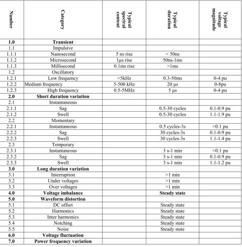
2. POWER QUALITY PARAMETERS
Power quality parameters are used to describe a wide range of supply voltage waveform distortions. It is important to precisely classify the parameters relevant to power quality in order to recognize them, to find the generation origin and ultimately to obey cancellation techniques. Table 1 represents this classification according to IEEE STD 1159. In this table supply waveform distortions have been classified into seven overall parts. Transients are temporary phenomena, which are divided into impulse and oscillatory components. Short duration variations are normally
2
CO NTR OLSM OTORS
OTHER L OADS
3
4
1
Sensitive P rocess M achine
Utility Source
M achines G rou p O fFeeder O r Inside Plant Protection
3 - O verall 2 - Controls Custome r Solutions
1 - Equipment Specifications Utility Solutions
Protection
0 0.3 -400
0 400
0 0.3
-400 0 400
0 0.3
-400 0 400
0 0.3
-400 0
400 INTERRUPTION
0 0 . 3
- 4 0 0 0
4 0 0 F R E Q U E N C Y
caused by faults and are classified into immediate, instantaneous and temporary cases. Long-term variations are the result of load changes and switching. The unbalanced loads cause three-phase unbalanced voltages. Waveform distortions can be caused by steady-state harmonics. When the load current varies flicker occurs. Such loads
lead to voltage amplitude fluctuations. Power system frequency depends directly on the generator rotating speed which itself relates to the generator load. Frequency will vary over the period of the load change. Figure 2 presents some of the above-mentioned voltage waveform distortions.
TABLE 1. Classification of Power Quality Parameters.
Num
b
er
C
ategory Typic
al
sp
ectral
content Ty
pic
al
dura
tio
n
Ty
pic
al
vol
tage
m
agn
itu
d
e
1.0 Transient 1.1 Impulsive
1.1.1 Nanosecond 5 ns rise < 50ns
1.1.2 Microsecond 1µs rise 50ns-1ms
1.1.3 Millisecond 0.1ms rise >1ms
1.2 Oscillatory
1.2.1 Low frequency <5kHz 0.3-50ms 0-4 pu
1.2.2 Medium frequency 5-500 kHz 20 µs 0-8pu
1.2.3 High frequency 0.5-5MHz 5 µs 0-4 pu
2.0 Short duration variation
2.1 Instantaneous
2.1.1 Sag 0.5-30 cycles 0.1-0.9 pu
2.1.2 Swell 0.5-30 cycles 1.1-1.9 pu
2.2 Momentary
2.2.1 Instantaneous 0.5 cycles-3s <0.1 pu
2.2.2 Sag 30 cycles-3s 0.1-0.9 pu
2.2.3 Swell 30 cycles-3s 1.1-1.4 pu
2.3 Temporary
2.3.1 Instantaneous 3 s-1 min <0.1 pu
2.3.2 Sag 3 s-1 min 0.1-0.9 pu
2.3.3 Swell 3 s-1 min 1.1-1.2 pu
3.0 Long duration variation
3.1 Interruption >1 min
3.2 Under voltages >1 min
3.3 Over voltages >1 min
4.0 Voltage imbalance Steady state 5.0 Waveform distortion
5.1 DC offset Steady state
5.2 Harmonics Steady state
5.3 Inter harmonics Steady state
5.4 Notching Steady state
5.5 Noise Steady state
3. CUSTOM POWER TOOLS
Power electronic devices for protecting the users against power quality problems of distribution system are proposed as custom power tools. The most important of these devices are DVR, DSTATCOM and UPQC. Voltage source inverter is a converter used in the all above-mentioned tools. In order to be able to compare these tools with electronic tap-changer, the above-mentioned tools are briefly described in the following section.
A: DSTATCOM:
Figure 3 presents the basic structure of a DSTATCOM which operates in parallel with the mains. This tool is adjustable as a current source, thus it is capable to compensate capacitive or inductive components.
B. DVR
Fig. 4 shows the basic structure of DVR that operates in series with the mains and injects a compensating voltage. Control system of DVR
compares the mains voltage with the reference voltage and then injects the required voltage. This tool is taken as an adjustable voltage source and it is capable to compensate the voltage.
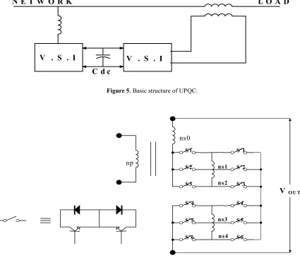
C. UPQC
A UPQC set consists of DVR and a DSTATCOM. Figure 5 shows the basic structure of the tool. This tool is able to compensate in parallel (current compensating) and in series (voltage compensating), thus allowing improved flexibility. It is noted that in each ofthe above-mentioned tools the energy of capacitor Cdc (VSI input) can be
taken from the mains or an energy storage system (such as battery).
4. ELECTRONIC TAP-CHANGER
High voltage and high current power electronic switches have made it possible to design full-electronic tap-changers. In this type of tap-changer, there are no moveable mechanical parts and thus it
Cdc
Voltage
Source
Inverter
L
C
VS
I
Figure 3. Basic structure of a DSTATCOM.
Cdc
Voltage
Source
Inverter
L
C
L
is quicker, lighter and efficient, with low volume. Meanwhile, the maintenance cost of electronic tap-changers is very low compared to the conventional mechanical tap-changer. Taking into account the above-mentioned advantages many attempts have been made to offer practical designs [9-13], with high reliability, low cost, with protection against short circuits and over voltages. The application of this device on the distribution transformers is proposed as one of the custom power tools [9-11]. In this section, this device is simulated and its capabilities are studied in power quality improvement. Figure 6 shows an optimal structure of an electronic tap-changer which is simulated in
this paper.
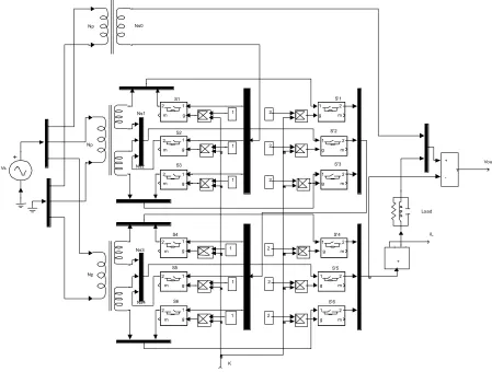
The system is simulated by power system blocks set of Simulink software. The simulation model has been presented in Figure 7. Since there is a transformer with maximum of two secondary windings in Simulink, the transformer with several secondaries shown in Figure 6, three transformers have been used where their primaries are in parallel. In order to connect the transformer terminals to each other, output and multi-input bus bar blocks have been employed. The semiconductor switches have been also modeled by an ideal switch block. Since the overall performance of an electronic tap-changer is
V . S . I V . S . I C d c
N E T W O R K L O A D
Figure 5. Basic structure of UPQC.
np
ns0
S1
S2
S3
S'1
S'2
S'3
S'4
S'5
S'6
S4
S5
S6
V OU T
ns1
ns2
ns3
ns4
considered, this assumption will not cause restrictions in the results obtained. Forty-nine different positions for Vout are obtained based on
the states of twelve switches: S1, S'1, S2, S'2,..., S6,
S'6. Table 2 shows these 49 positions for the output
voltage of transformer, having the following turns ratio with Vp=220 V.
ns0/np=210/220, ns1/np=2/220 ns2/np=4/220,
ns3/np=14/220, ns4/np=28/220
(1) In model of Figure 7, command K is equivalent
with the row number in Table 2. The data in Table 2 has been given by a look-up-table when K refers to the row number; the states of the proposed switches are created. The contents of Table 2 are
entered to six two-row look-up-tables (the reason is the limitation of look-up-tables in Simulink software). Information due to each pair of switches Si and S'i are summarized in a look-up-table. A
linear RLC circuit has been used as a load. Varying the components of RLC circuit can change peak load current and also power factor.
In fact, Figure 7 can fully model the power part of the electronic tap-changer. Vout and IL (load
current) signals return to the control circuit as feedback, and output of the control circuit determines command K (state of twelve-switches). The control circuit operates as such that Vout
remains constant against input voltage and load current variations. In order to minimize the losses and the switching stresses, the states of the switches are allowed to vary only when it crosses
S1 S2 S3 S4 S5 S6 S'1 S'2 S'3 S'4 S'5 S'6 Vout iL K Vs Np Ns0 Np Ns1 Ns2 Ns3 Ns4 Np Load + -v 1 g 2 m 1 g 2 m 1 g 2 m 1 g 2 m 1 g 2 m 1 g 2 m 1 g 2 m 1 g 2 m 1 g 2 m 1 g 2 m 1 g 2 m 1 g 2 m + i -2 2 2 2 2 1 1 1 1 1 1 2
the zero. Thus, the command to vary K is issued when IL crosses zero. Therefore, there are two
possibilities of varying the switch state in every cycle. Here one of advantages of the electronic tap-changer is clear. In a mechanical tap-tap-changer, one state of the switch takes several seconds, while in an electronic tap-changer such action is possible in every half-cycle. Meanwhile, it is noted that changing the position of the mechanical tap-changer come along with losses and stress while changing of electronic tap-changer occurs at zero current (ZCS) in which the losses and stress are minimal. On the other hand, in mechanical tap-changer, switch states are changed step by step while it is possible to jump from K=1 to K=49 in every half-cycle in an electronic tap-changer which speeds up the control rapidly. The advantage of the solid-state tap-changer jump can be considered as an inherent feature of this tap-changer. However, practical realization of this advantage and its application requires necessary considerations related to the control and power system. Rapid rise
of voltage causes a large capacitive current and this may damage the tap-changer or generate a notch in the network, but the level of this current is determined based on the capacitance of the load system. It is noted that simulation for six steps in the tap-changer is due to the control system used and not limitation of the tap-changer.
In order to remove the high capacitive currents in step changes with large jumping it is possible to employ ZVC, but decision on the ZVC or ZCS depends on the nature of the load. Certainly if the load is largely capacitive, the ZVS may lead to lower losses, otherwise, ZCS is preferred due to its lower losses.
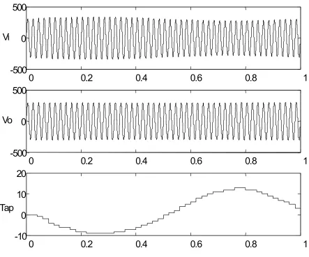
Figure 8 exhibits the simulation results for variations of input voltage from 220 Vrms to 240
Vrms and then 200 Vrms and finally returning to 220
Vrms at t=0.2s, t=0.5s and t=0.8s. In this simulation
the control system does not allow more than six units change in each change of K. It is observed that the output voltage is quickly regulated. Figure 9 presents the simulation results for the following
0 0.2 0.4 0.6 0.8 1
-400-300 -200 -1000 100 200 300400
0 0.2 0.4 0.6 0.8 1
-400 -300 -200 -1000 100 200 300 400
0 0.2 0.4 0.6 0.8 1
-12-9 -6 -30 3 6 9 12 Vi
Vo
Tap
input voltage waveform:
)
2
sin
1
.
0
1
(
100
sin
2
220
t
t
V
i=
π
+
π
(1)
As seen the envelop of the output voltage is not varied sinusoidally.
So far, the possibility of application of a high frequency modulation technique in switching of solid-state switches has not been discussed. This feature is realized considering the controllability and quick operation of the solid-state switches. In
fact, in the above-mentioned technique, similar to the mechanical tap-changer, switching is carried out only during the tap-changing period and in the remaining time the states of switches are fixed. The major advantage of this technique is lower switching losses, non-existing troublesome switching harmonics in the steady state. Although high frequency harmonics are produced (which must be eliminated by a proper filter) and larger switching losses exist (which must be minimized by soft-switching techniques) in the high frequency modulation technique, the output voltage will be continuously controlled and the output voltage waveform will be instantaneously modified.
0
0.2
0.4
0.6
0.8
1
-500
0
500
0
0.2
0.4
0.6
0.8
1
-500
0
500
0
0.2
0.4
0.6
0.8
1
-10
0
10
20
Vi
Vo
Tap
TABLE. 2. Different Values of Output Voltages Versus Twelve Switch Positions of Electronics Tap-Changer.
States of switches
No
.
S1 Ś1 S2 Ś2 S3 Ś3 S4 Ś4 S5 Ś5 S6 Ś6
V
ou
t – V
nso
(V)
1 0 1 0 0 1 0 0 1 0 0 1 0 - 48
2 0 0 0 1 1 0 0 1 0 0 1 0 - 46
3 0 1 1 0 0 0 0 1 0 0 1 0 - 44
4 1 1 0 0 0 0 0 1 0 0 1 0 - 42
5 1 0 0 1 0 0 0 1 0 0 1 0 - 40
6 0 0 1 0 0 1 0 1 0 0 1 0 - 38
7 1 0 0 0 0 1 0 1 0 0 1 0 - 36
8 0 1 0 0 1 0 0 0 0 1 1 0 - 34
9 0 0 0 1 1 0 0 0 0 1 1 0 - 32
10 0 1 1 0 0 0 0 0 0 1 1 0 - 30
11 1 1 0 0 0 0 0 0 0 1 1 0 - 28
12 1 0 0 1 0 0 0 0 0 1 1 0 - 26
13 0 0 1 0 0 1 0 0 0 1 1 0 - 24
14 1 0 0 0 0 1 0 0 0 1 1 0 - 22
15 0 1 0 0 1 0 0 1 1 0 0 0 - 20
16 0 0 0 1 1 0 0 1 1 0 0 0 - 18
17 0 1 1 0 0 0 0 1 1 0 0 0 - 16
18 1 1 0 0 0 0 0 1 1 0 0 0 - 14
19 1 0 0 1 0 0 0 1 1 0 0 0 - 12
20 0 0 1 0 0 1 0 1 1 0 0 0 - 10
21 1 0 0 0 0 1 0 1 1 0 0 0 - 8
22 0 1 0 0 1 0 1 1 0 0 0 0 - 6
23 0 0 0 1 1 0 1 1 0 0 0 0 - 4
24 0 1 1 0 0 0 1 1 0 0 0 0 - 2
25 1 1 0 0 0 0 1 1 0 0 0 0 0
26 1 0 0 1 0 0 1 1 0 0 0 0 2
27 0 0 1 0 0 1 1 1 0 0 0 0 4
28 1 0 0 0 0 1 1 1 0 0 0 0 6
29 0 1 0 0 1 0 1 0 0 1 0 0 8
30 0 0 0 1 1 0 1 0 0 1 0 0 10
31 0 1 1 0 0 0 1 0 0 1 0 0 12
32 1 1 0 0 0 0 1 0 0 1 0 0 14
33 1 0 0 1 0 0 1 0 0 1 0 0 16
34 0 0 1 0 0 1 1 0 0 1 0 0 18
35 1 0 0 0 0 1 1 0 0 1 0 0 20
36 0 1 0 0 1 0 0 0 1 0 0 1 22
37 0 0 0 1 1 0 0 0 1 0 0 1 24
38 0 1 1 0 0 0 0 0 1 0 0 1 26
39 1 1 0 0 0 0 0 0 1 0 0 1 28
40 1 0 0 1 0 0 0 0 1 0 0 1 30
41 0 0 1 0 0 1 0 0 1 0 0 1 32
42 1 0 0 0 0 1 0 0 1 0 0 1 34
43 0 1 0 0 1 0 1 0 0 0 0 1 36
It is concluded that if a high frequency modulation is used in an electronic tap-changer, this system can better perform its duties as tap-changer (high speed and possibility of quick jumps) and possibility of controlling the output voltage instantly. Present work and simulations emphasize of the solid-state tap-changer in which there are possibility of tap-changing only when cross the zero (every 10 ms). Possibility of using high frequency modulation in the solid-state tap-changer has been discussed in Reference 9.
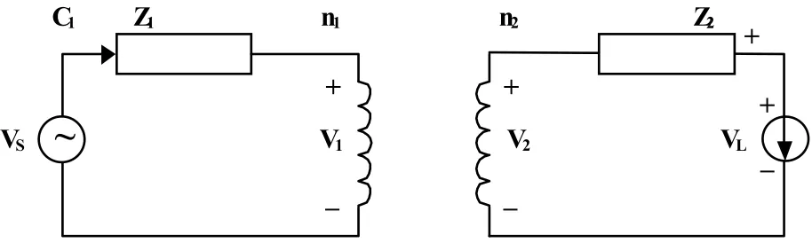
It must now be determined that how much voltage drop may be compensated by a tap-changer. Consider Figure 10, where small letters denote time-dependent parameters and capital letters show the phasors. In this model, the phase difference between iL and vL is θL. Thus, the
following equation is obtained for VL:
L L
s
L
XV
X
Z
I
Z
I
V
=
−
2 1−
2(2)
where X=n2/n1. If load impedance is ZL, (2) will
be as follows:
L L s L
Z
Z
Z
Z
X
XV
V
2 1 21
+
+
=
(3) The aim is by varying iL and vs, the amplitude
of vL remains constant. If this constant value is
denoted by Vc then:
2 2 2 1 1 2 1 1 2 2 2
)]
sin(
|
|
|
|
)
sin(
|
|
|
|
[
)]
cos(
|
|
|
|
)
cos(
|
|
|
|
1
[
)
|
|
|
|
(
L L L L L L L L c sZ
X
Z
Z
Z
X
Z
Z
X
Z
X
Z
X
V
V
θ
θ
θ
θ
θ
θ
θ
θ
−
+
−
+
−
+
−
+
=
(4) It is seen that the adjustable range of X for makingVL equal to Vc depends on Vc. |Vs|, Z1, Z2, ZL. θ1,
θ2 and θL. X are obtained by solving the 4th order
equation (4). If all impedance in Figure 10 are taken to be resistive, i.e. θ1=θ2=θL=0, (4) will be
simplified as:
0
1
2 1
2
+
−
+
=
c s L L
V
V
X
Z
Z
Z
Z
X
(5) There is solution for X of (5) if the roots are realand positive. It can be shown that (6) is the necessary and sufficient condition for positive and real solution for (5).
L L c s
Z
Z
Z
Z
V
V
)
24
(
1
2)
1|
|
|
|
(
≥
+
(6) Assuming Z1Z2≤ZL2 , Equation 6 will be simplified~
+
_
V
1V
SC
1Z
1n
1+
_
V
LV
2Z
2n
2+
_
+
TABLE 3.Comparison of Capabilities of Electronic Tap-Changer With Dstatcom For Eliminating The Power Quality.
No.
Category Tap-Ch. With Electronics
Pw
m
E
lectronics
Tap-Ch.
DVR Dstatcom
1.0 Transient 1.1 Impulsive
1.1.1 Nanosecond No No No No
1.1.2 Microsecond No No No No
1.1.3 Millisecond Yes No Yes Yes
1.2 Oscillatory
1.2.1 Low frequency Yes No Yes Yes
1.2.2 Medium frequency No No No No
1.2.3 High frequency No No No No
2.0 Short duration variation
2.1 Instantaneous
2.1.1 Sag Yes Yes Yes No
2.1.2 Swell Yes Yes Yes No
2.2 Momentary
2.2.1 Interruption No No No No
2.2.2 Sag Yes Yes Yes No
2.2.3 Swell Yes Yes Yes No
2.3 Temporary
2.3.1 Interruption No No No No
2.3.2 Sag Yes Yes Yes No
2.3.3 Swell Yes Yes Yes No
3.0 Long duration variation
3.1 Interruption No No No No
3.2 Under voltages Yes Yes Yes Yes
3.3 Over voltages Yes Yes Yes Yes
4.0 Voltage imbalance
5.0 Waveform distortion
5.1 DC offset Yes Yes Yes No
5.2 Harmonics Yes No Yes No
5.3 Interharmonics Yes No Yes No
5.4 Notching Yes No Yes No
5.5 Noise No No No No
6.0 Voltage fluctuation Yes Yes Yes Yes
as follows:
L c
s
Z
Z
V
V
)
24
1|
|
|
|
(
≥
(7)X is changed by tap-changer.
5. COMPARISON OF TAP-CHANGER WITH OTHER CUSTOM POWER TOOLS
Table 3 compares the capability of electronic tap-changer with DVR and DSTATCOM in eliminating the power quality difficulties. As seen, tap-changer with high frequency modulation is also considered. As shown in Table 3, in this simulation the high frequency electronic tap-changer operates similar to a ac/ac converter and controls the output instantaneously, it has all capabilities of DVR and DSTATCOM. It also has reasonable capabilities of eliminating sag, swell and low-frequency flickers.
6. CONCLUSIONS
This paper briefly introduced an electronic tap-changer. The capability of the distribution transformer equipped with such tap-changer in improving power quality was presented. The simulation results show that some problems such as sags, swells and voltage fluctuations can be eliminated or largely minimized by the electronic tap-changer. In addition, the performance of the electronic tap-changer compared with two custom power tools, DVR and DSTATCOM. The results indicated that the electronic tap-changer, even in the case of high frequency switching are fully comparable with other tools.
7. ACKNOWLEDGEMENTS
The authors wish to thank the University of
Tehran for financial support of "A new electronic tap-changer for transformer and designing a prototype" project under grant No. 612.1.530.
8. REFERENCES
1. Parihar, P. and Liu, E., “Power Quality Services: Technologies and Strategies for Energy Providers in the Deregulated Market”, The Electricity
Journal, Elsevier Science Inc., (November 1999),
79-84.
2. Dugan, Roger C., McGranaghan, Mark F. and Beaty, H. Wayne, “Electrical Power Systems Quality”, McGraw-Hill, (1996).
3. Woodly, N. H., Sarkozi, M. A., Sandaram and Taylor, G. A., “Custom Power: The Utility Solution”, CIRED, Brussels, Belgium, Vol. 5, (May 1995), 9/1-6.
4. Middlekauff, S. W. and Collins, E. R., “System and Customer Impact: Considerations for Series Custom Power Devices”, IEEE Transactions on Power
Delivery, Vol. 13, No. 1, (January 1998), 278-282.
5. Heydt, G. T., Tan, W., LaRose, T. and Negley, M., “Simulation and Analysis of Series Voltage Boost Technology for Power Quality Enhancement”, IEEE
Transactions on Power Delivery, Vol. 13, No. 4,
(October 1998), 1335-1341.
6. Wang, P., Jenkins, N. and Bollen, M. H. J., “Experimental Investigation of Voltage Sag Mitigation by an Advanced Static Var Compensator”, IEEE Transactions on Power
Delivery, Vol. 13, No. 4, (October 1998),
1461-1467.
7. Woodly, N., Sarkozi, M. Lopez, F., Tahiliani, V. and Malkin, P., “Solid-State 13-kV Distribution Class Circuit Breaker: Planning, Development and Demonstration”, IEE Conf. on Trends in Distribution
Switchgear, London, U.K., (November 1994),
163-167.
8. Lasseter, R. H. and Jalali, S. G., “Power Conditioning Systems for Superconductive Magnetic Energy Storage”,
IEEE Transactions on Energy Conversion, Vol. 6, No.
3, (September 1991), 381-386.
9. Bauer, P. and DeHaan, S. W. H., “Electronic Tap Changer for 500kVA/10kV Distribution Transformer: Design, Experimental Results and Impact in Distribution Networks”, IEEE IAS Annual Meeting, Vol. 2, (1998), 1530-1537.
10. Meyer, A. S. and Van Coller, J., “Electronic Tap Changers for Use with Ultra-Light Rural Distribution Lines”, IEEE Africans, Vol. 2, (1999), 909-912. 11. Demiric, O., Torrey, D. A., Degeneff, R.C, Schaffer, F.
K. and Frazer, R. H., “A New Approach to Solid-State on Load Tap Changing Transformers”, IEEE
Transactions on Power Delivery, Vol. 13, (1998),
12. Villegas, G., Vaquero, J. Echavarria, R., Horta, S., Perez, M. A. and Martinez, S., “Quasi-Resonant Fast on-Load Two Tap Changing Stabilizer: Towards The AC Soft Swiching”, IEEE Power Electronics Congress, (1998),
177-183.