International Journal of Engineering
J o u r n a l H o m e p a g e : w w w . i j e . i rCrack Detection in Functionally Graded Beams using Conjugate Gradient Method
M. Eftekhari*a, M. Eftekharib, M. Hosseinic
a Department of Mechanical Engineering, Shahid Bahonar University of Kerman, Kerman, Iran b Department of Mechanical Engineering, Yazd University, Yazd, Iran
c Department of Mechanical Engineering, Sirjan University of Technology, Sirjan, Iran
P A P E R I N F O
Paper history:
Received 24 December 2012 Received in revised form 24 June 2013 Accepted 22 August 2013
Keywords:
Functionally Graded Beam Crack Detection
Conjugate Gradient Method
A B S T R A C T
In this paper, the conjugate gradient (CG) method is employed for identifying the parameters of crack in a functionally graded beam from natural frequency measurement. The crack is modeled as a massless rotational spring with sectional flexibility. Using the Euler-Bernoulli beam theory on two separate beams and applying the compatibility requirements of the crack, the characteristic equation can be obtained as a function of natural frequency and location and depth of crack. In direct problem, the natural frequency is computed using analytical analysis. Moreover, the location and depth of crack are determined by measuring the three natural frequencies of beam in inverse problem. In this study, the CG method is utilized in inverse problem to determine the location and depth of crack. The obtained results show the efficiency of CG algorithm in terms of accuracy and the convergence speed.
doi:10.5829/idosi.ije.2014.27.03c.03
1. INTRODUCTION1
A crack in a structural member introduces local flexibility that would change the dynamic behavior of the structure. Changes in overall dynamic of structure might be used to indicate the existence, location and depth of cracks. Several analytical, numerical and experimental methods are studied on the dynamic behavior of cracked structures [1-7]. In this field, a crack in a beam subjected to various boundary conditions is modeled by many researchers [8-11]. In their analyses, two categories of crack modeling are: open crack model and breathing crack model. The model is considered according to the vibration amplitude or loading conditions [9].
Functionally graded materials are inhomogeneous composites which have found an increasing application in space structures, fusion reactors and so on. Over the past few years, many researchers have investigated the dynamic response of FGM structures [3, 5, 12, 13]. Literature review shows that the dynamic behavior of cracked FGM structure has not been considered very
1*Corresponding Author Email: [email protected] (M. Eftekhari)
perfectly. In what follows, the related works to the analysis of the FGM cracked beams are presented.
optimization method. The methodology was applied to beam-like structures and any other arbitrary shaped 3D element. The input data in algorithm were obtained with a cantilever damaged beam in physical experiments.
Zhigang and Fulei [17] presented the p-version of finite element method to identify position and size of the open edge crack in FGM beams. In their study, the effects of location and size of crack on natural frequencies have been investigated. Experimental results were showing the effectiveness of the proposed method. Byrd and Birman [18] examined free and forced vibration of damaged FGM beam. They extended their work to modeling damage to region with degraded stiffness adjacent to the fixed point of the beam, a single delamination crack and a single crack at the root cross section of the beam [19]. Moradi and et al. [20] proposed the bees algorithm to detect the crack in cantilever beam. Kang et al. [21] was utilized the experimental data to detect the parameters of crack by an improved particle swarm optimization. A hybrid stochastic/deterministic algorithm was used by Miguel et al. [22]. Results were showing that the new method was more accurate than the other algorithms which were presented in pervious works.
Among the sparse works of cracked FGM beams, the objective of this paper is to estimate the location and size of crack in FGM beam by conjugate gradient method. No previous works have been done regarding to the crack identification by this method in FGM beams. The open crack is modeled by a massless rotational spring. The governing equation and boundary conditions is obtained using the extended Hamilton’s principle on two separate Euler-Bernoulli beams. By employing the boundary conditions, the characteristic equation is obtained as a function of position ratio of crack, depth ratio of crack and Young modulus ratio. Three natural frequencies of beam are evaluated from analytic solution for a considered Young modulus once the location and depth of crack are determined. Conjugate gradient method can be utilized for computing the parameters of crack (position and depth) given the natural frequencies of FGM beam as inputs.
2. MATHEMATICAL MODELING AND
FORMULATION
1. 2. The Rotational Spring FGM Beam Model A
cantilever FGM beam of length L and thickness h, containing an edge crack of depth a located at position
1
L from the clamped end is shown in Figure 1. Young modulus and density of beam follow exponential distribution as
, , )
(
, )
(
1 ) ( ) / ( 1
) ( ) / ( 1
n n r
r = =
=
k Ln h z
k Ln h z
e k z
e k E z
E (1)
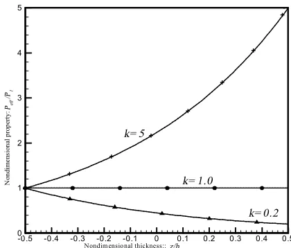
where, E1,r1,n1 are Young’s modulus, density and Poisson’s ratio at z=-h/2 respectively and E2 is the Young’s modulus at z=h/2. Moreover, k is defined as k=E2/E1 . A number of researchers has previously used the exponential law of the material properties and this law is more common in fracture studies of FGM materials [23, 24]. The material distribution in the thickness direction of the E-FGM beams is depicted in Figure 1 for three values k equal to 0.2, 1 and 5. As shown in Figure 1, the property changes ascending for
1 >
k , and changes descending for k<1 and is constant for
k
=1. Note that material properties are homogeneous and isotropic whenk=1. Figure 2 shows a FGM cantilevered beam with the crack model. As shown in Figure 2(b), the crack section is modeled as a massless rotational spring. Based on this model, the entire beam is divided in two sub-beams which are connected by the rotational spring whose bending stiffness of the cracked section, KT, is given as, 1 G
KT= (2)
where, G is the flexibility due to the crack and can be derived from the Broke assumption [25] as
da dG M K
a E
I
I 2 2
2
) 2 ( ) ( ) ( 1
= -n
(3)
where, MI,E(a) is the bending moment at the cracked section and Young’s modulus at the crack tip respectively and KI is the stress intensity factor (SIF) under mode-I loading. The SIF parameter is a function of the geometry, the loading, and the material properties.
Figure 1. The variation of material properties in an E-FGM beam.
+ +
+ +
+ +
+ +
z/h Peff
/P1
-0.5 -0.4 -0.3 -0.2 -0.1 0 0.1 0.2 0.3 0.4 0.5 0
1 2 3 4 5
k= 5
k= 0.2 k= 1.0
Nondim ensional thickness::
N
on
di
m
en
si
on
al
pr
op
er
ty
a) An FGM beam with an open edge crack
T K
b) Rotational spring model
Figure 2.Schematic of cantilever beam and crack model
Through the Lagrange interpolation technique, the formulas for the SIF can be obtained from the data given by Erdogan and Wu [26] as follows
), ( 6 2 z z p F h h M
KI = I z = h,z £0.7,
a
(4)
where, the crack depth ratio (z) is in interval 0.0 to 0.7 and F(z) is expressed in Equations (5) to (7) as
, 2 . 0 / , 762 . 1 3 . 0 225 . 24 387 . 170 549 . 554 567 . 1009 767 . 971 919 . 395 ) ( 1 2 2 3 4 5 6 7 = + + -+ -+ -= E E for F z z z z z z z z (5) , 1 / 150 . 1 662 . 1 667 . 21 451 . 192 375 . 909 310 . 2124 830 . 2395 750 . 1031 ) ( 1 2 2 3 4 5 6 7 = + -+ -+ -+ -= E E for F z z z z z z z z (6) , 5 / , 605 . 0 300 . 0 860 . 0 567 . 12 003 . 94 533 . 249 701 . 296 978 . 122 ) ( 1 2 2 3 4 5 6 7 = + + + -+ -+ -= E E for F z z z z z z z z (7)
Substituting Equation (4) into Equation (3) leads to
z z z z n p z d h h E F G 2 2 2
0 ( )
) ( ) 1 ( 72
-=
ò
(8)By substituting Equation (8) in Equation (2), the bending stiffness of the cracked section (KT) is obtained.
2. 2. Governing Equations Based on Euler-Bernoulli beam theory, displacement of an arbitrary point in the beam along the x and z axis are
), , ( ) , , , ( , ) , ( ) , ( ) , , , ( 0 0 0 t x w t z y x w x t x w z t x u t z y x u = ¶ ¶ -= (9)
where, u0(x,t),w0(x,t) are displacement components in mid-plane. The strain-displacement relation is given as
, , , 20 2 1 0 0 1 0 x w x u z xx xx xx xx xx ¶ ¶ -= ¶ ¶ = + = e e e e e (10)
where, exx0,e1xxare strains due to mid-plane and bending, respectively. The normal stress sxx is related to the strain through the linear constitutive law as
ú ú ú û ù ê ê ê ë é ú ú ú û ù ê ê ê ë é = ú ú ú û ù ê ê ê ë é xy yy xx xy yy xx Q Q Q Q Q g e e s s s 66 22 12 12 11 0 0 0 0 (11) ) 1 ( 2 , 1 , 1 66 2 21 12 2 22 11 n n n n + = -= = -= = E Q E Q Q E Q Q (12)
From Equations (9) to (12), variation of kinetic energy and potential energy for the cracked FGM beam are obtained as , ) ( ) ( 2 / 2 / 2 / 2 / 0 1 1
ò
ò
ò
ò
-+ -+ -= h h L L h h L dx bdz w w u u dx bdz w w u u T d d r d d r d & & & & & & & & (13) ), x ) L ( w x ) L ( w ( K dx bdz ) ( dx bdz ) ( V o o T xx xx / h / h L L xx xx / h / h L ¶ ¶ -¶ ¶ + de s + de s = d -+-ò
ò
ò
ò
1 1 2 2 2 2 0 1 1 (14)By substituting Equations (13), (14) in to the extended Hamilton’s principle given in Equation (15), and noting the fact that du0,dw0 are arbitrary, the governing equation of motion for ith segment (i=1,2) are obtained in Equations (16) and (17)
, , , 0 , 0 ) ( 2 1 0 0 2 1 t t t at w u dt V T t t = = = =
-ò
d d d d (15) 0: 3 3oi
11 2oi 2 11 = ¶ ¶ -¶ ¶ x w B x u A uoi d (16) , 0 ) (
: 4oi 1
4
11 2 11
11 + =
¶ 
- oi
oi Iw
x w A B D
w &&
d (17) 1 2 a 1 L L
h
z1, 1
E r
2, 2
E r
where, subscript i=1,2 refer to the left sub-beam and the right sub-beam, respectively, which is divided with crack.
Moreover, it is assumed that in Equations (16) and (17) the in-plane inertia and rotary inertial effects are negligible. The parameters I1,A11,B11,D11are defined as
, ) , , 1 ( ) ( ) , , ( , ) ( 2 2 2 11 11 11 2 2 1 dz z z z E D B A dz z I h h h h ò ò -= = r (18)
And the boundary conditions are
, 0 , 0 , 0 ,
0 0= =
¶ ¶ =
= at x
x w w
uo o (19)
, , 0 2o 2 11 o
11 at x L
x w B x u
A = =
¶ ¶ -¶ ¶ , , 0 3o 3 11 2o 2
11 at x L
x w D x
u
B = =
¶ ¶ -¶ ¶ , , 0 2 o 2 11 o
11 at x L
x w D x u
B = =
¶ ¶ -¶ ¶ (20) , ,
, 01 02 1 2
02
01 u w w Nxx Nxx
u = = =
, , , , 1 2 1 1 2 1 2 1 L x at dx dw K M dx dw K x M x M M M o T xx o T xx xx xx xx = = -¶ ¶ = ¶ ¶ = (21)
where, the stress resultant Nxx (force per unit length) and the stress moment Mxx (moment per unit length), are defined as the following integral expressions
, 2 / 2 / dz N xx h h
xx =ò- s M //22 xxzdz, h
h
xx=ò- s (22)
2. 3. Direct Solution In direct problem, eigen solutions for the cantilevered boundary conditions are derived using the following separable solutions
, ) ( ) , ( oi
oi xt U xej t
u = w
, 2 , 1 , ) ( ) , ( oi
oi xt =W xe i=
w jwt (23)
where, w is the natural frequency of the cracked FGM beam. Substituting Equation (23) in to Equations (16) and (17), the displacement fields for each segment are obtained as ), cosh( ) sinh( ) cos( ) sin( 4 3 2 1 x e x e x e x e W i i i i oi l l l l + + + = (24) , )] sinh( ) cosh( ) sin( ) cos( [ 0 4 3 2 1 11 11 i i i i i i oi g x g x e x e x e x e A B U + + + + -= l l l l l (25) where, ), ( , 11 2 11 11 4 2 1 A B D d d
I =
-= w
l (26)
By substituting Equations (24) and (25) in to the boundary conditions given by Equations (19) to (21), we can express them in matrix form as
}, 0 { } ]{
[H q = (27)
where, H is a square matrix as Equations (28) and (29).
[ ] = ⎣ ⎢ ⎢ ⎢ ⎢ ⎢ ⎢ ⎢ ⎢ ⎢ ⎢ ⎢ ⎢ ⎢
⎡ 00 01 00 01 00 01 00 00 00 00 00 00
1 0 1 0 0 0 0 0 0 0 0 0
0 0 0 0 0 0 0 0 0 0 1 0
0 0 0 0 0 0 − − 0
0 0 0 0 0 0 − 0 0
− 1
− −1
0 0 − − − − 0 0
0 0 0 0 1 0 0 0 0 0 −1 0
− − 0 − − 0
− 0 0 − − − 0 0
− + + − 0 − − − 0 0⎦⎥
⎥ ⎥ ⎥ ⎥ ⎥ ⎥ ⎥ ⎥ ⎥ ⎥ ⎥ ⎥ ⎤ (28) ), cosh( ), sinh( ), cos( ), sin( ), cosh( ), sinh( ), cos( ), sin( 1 41 1 31 1 21 1 11 40 30 20 10 L J L J L J L J L J L J L J L J l l l l l l l l = = = = = = = =
{
e e e e g g e e e e g g}
Tq} 11 12 13 14 1 10 21 22 23 24 2 20
{ =
Thus, the characteristic equation which ensures the non-trivial solution is
0 ) ( )])
(
det([ H l = H l = (30)
Natural frequencies are obtained by solving Equation (30). Note that the natural frequency now depends not only on the crack depth and location, but also on the material. This equation can be solved analytically for certain values of location and depth of crack.
2. 4. Inverse Solution In inverse problem of the cracked system, the location and depth of crack are computed when the value of natural frequencies are known. By substituting the measured natural frequencies in to characteristic equation (Equation (30)), there are only unknown parameters l1/l,a/h which are the non-dimensional position and depth of crack, respectively. Several non-linear equation solving algorithms can be used for this problem. In this paper, these unknown parameters are solved using the conjugate gradient method [27].
In crack detection process, a location and depth of crack are considered as reference location and depth and the first three natural frequencies are obtained analytically from the characteristic equation. The natural frequencies are named as analytical natural frequencies. Then, for simulation of experimental data, the percent of error is added to these analytical values and they are entered as input to the inverse algorithm. The conjugate gradient algorithm is evaluated the location and depth of crack which are compared to the values of references. The ratio of reference natural
frequency (( )*) oi ci
w w
is expressed as
i c
oi ci
oi
ci erre
w w w
w
. ) ( )
( *= + ,i=1,2,3.
(31)
where , e is a random number at interval [-0.5, 0.5],
err
is the magnitude rate of error which is consideredas 0% 1% or 2% in this paper and c oi ci) (
w
w is the rate of
analytical natural frequency.
2. 5. Conjugate Gradient Method The conjugate gradient algorithm is an iterative algorithm for solving linear and nonlinear problems [27]. This method is used to minimize the summation of quadratic form in estimation problems. The algorithm selects the successive direction vectors based on the gradients such that at each step of iteration the process makes the good uniform progress to the solution. At each step the current negative gradient vector is computed and is added to a linear combination of the previous direction
vectors to obtain a new conjugate direction vector. In conjugate gradient formulation, the minimization of quadratic norm is introduced as
[
]
å
= -= I
i i i
T Y S
1
2
) ( )
(P P (32)
where, in Equation (30), S(P)is the summation of quadratic errors (objective function), PT=[P1,P2,...,PN] is unknown parameters vector, N is number of parameters, I is number of sampling and Ti(P),Yi are estimated and sampled quantity for i-th measured point, respectively. By expanding the tailor series for estimated values P, we get
) ( ) ( )
(P TPk Xk P Pk
T = + - (33)
where, Xij=[¶Ti/¶Pj] is the sensitivity matrix. The matrix is computed in the given algorithm in Table 1 from finite difference method. By substituting Equation (33) in to Equation (32) and minimizing the error function, resulting to the following iteration formula
k k k
k P d
P +1= -b
[
] ( )
[
]
[
k k] [
T k k]
k T k k k
d X d X
Y P T d
X
-=
b (34)
where, dk is the new conjugate gradient direction which is obtained from linear combination of gradient vector in the k and k-1 steps as
( )
P d 1dk =ÑS k + gk k- (35)
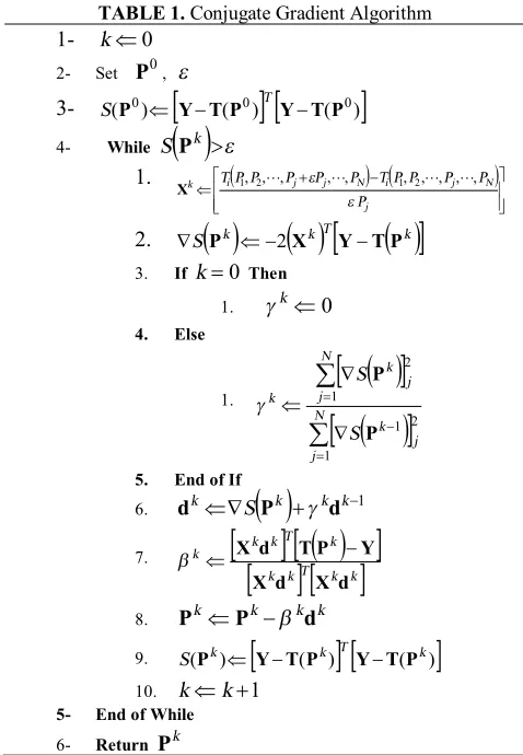
From the several choices for gk, the Fletcher-Reeves [28] expression is considered in the given algorithm in Table 1. This algorithm terminates when S(Pk+1)<e for a CG error tolerance e <1. The conjugate gradient algorithm is presented in Table 1.
3. RESULTS AND DISCUSSION
3. 1. Direct Solution Veriication In order to validate the accuracy of analytical solution of direct problem. The fundamental frequency ratio w1/w10of a cracked cantilevered isotropic beam is computed at different locations. Moreover, w10 is the first natural frequency of the intact beam. Table 2 shows the fundamental frequency ratio of an isotropic homogenous cantilevered beam with the properties
) 2 . 0 / , 3 . 0 , 0 . 4 /
(L h= n = a h= . This example was
TABLE 1. Conjugate Gradient Algorithm
1- kÜ0
2- Set P0, e
3- S(P0)Ü
[
Y-T(P0)] [
T Y-T(P0)]
4- While S( )
Pk >e1.
(
) (
)
ú ú û ù ê
ê ë
é +
-Ü
j
N j i N j j i k
P
P P P P T P P P P P T
e
e , , , , , , , ,
,
,2 1 2
1 L L L L
X
2. ÑS
( )
Pk Ü-2( )
XkT[
Y-T( )
Pk]
3. Ifk=0 Then
1. gkÜ0
4. Else
1.
( )
[
]
( )
[
]
å
å
= -=
Ñ Ñ
Ü N
j j
k N
j j
k
k
S S
1
2 1 1
2
P P
g
5. End of If
6. dkÜÑS
( )
Pk +gkdk-17.
[ ]
[
( )
]
[ ] [ ]
k kT k k k T k k kd X d X
Y P T d
X
-Ü
b
8. PkÜPk-bkdk
9. S(Pk)Ü
[
Y-T(Pk)] [
T Y-T(Pk)]
10. kÜk+15- End of While
6- Return Pk
TABLE 2. Fundamental frequency ratio w1w1o of an isotropic homogenous cantilevered beam ( =4.0, =0.3, =0.2)
h a h
L n
2 . 0
1 =
L L
4 . 0
1 =
L L
6 . 0
1 =
L L
Ref. 29 present Ref. 29 present Ref. 29 present
0.9410 0.9656 0.9667 0.9856 0.9958 0.9964
TABLE 3. First three dimensionless natural frequencies of intact FGM cantilevered beams
) / 2780 , 33 . 0 , 70
( 3
1 GPa kg m
E = n = r=
h L
1 2 E
E w1 w2 w3
Ref.
17 present Ref.
17 present Ref.
17 present
20 0.2
1 5
0.83 0.88 0.83
0.83 0.88 0.83
5.18 5.51 5.18
5.18 5.51 5.18
14.49 15.42 14.49
14.49 15.42 14.49
10 0.2
1 5
3.30 3.52 3.30
3.30 3.52 3.30
20.70 22.03 20.70
20.70 22.03 20.70
57.97 61.70 57.97
57.97 61.70 57.97
In Table 3, the lowest three modal frequencies of the intact FGM cantilevered beam are calculated by the present method and are compared with those reported by Yu and Chu [17]. In their work, the p-FEM was used for calculation of frequencies and the modal frequencies were normalized as follow:
o o
n n
I d /
w
w = (36)
where, d0 and I0 are the corresponding values of d0
and I0 of an isotropic homogeneous beam E2/E1=1. Table 3 shows that the obtained results are in conformity with the results of paper [17].
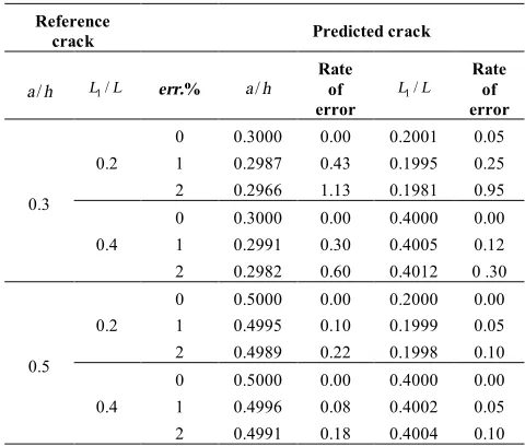
TABLE 4. Comparison of reference crack parameters with the predicted values obtained by inverse algorithm (E2 E1=1)for ten simulation
Reference
crack Predicted crack
h
a/ L1/L err.% a/h Rate of error L1/L Rate of error
0.3 0.2
0 1 2
0.3000 0.2987 0.2966
0.00 0.43 1.13
0.2001 0.1995 0.1981
0.05 0.25 0.95
0.4 0 1 2
0.3000 0.2991 0.2982
0.00 0.30 0.60
0.4000 0.4005 0.4012
0.00 0.12 0 .30
0.5 0.2
0 1 2
0.5000 0.4995 0.4989
0.00 0.10 0.22
0.2000 0.1999 0.1998
0.00 0.05 0.10
0.4 0 1 2
0.5000 0.4996 0.4991
0.00 0.08 0.18
0.4000 0.4002 0.4004
0.00 0.05 0.10
TABLE 5. Comparison of reference crack parameters with the predicted values obtained by inverse algorithm (E2 E1=0.2) for ten simulation
Reference
crack Predicted crack
h
a/ L1/L err.% a/h Rate of error L1/L Rate of error
0.3 0.2
0 1 2
0.3000 0.2991 0.2979
0.00 0.30 0.70
0.2001 0.1997 0.1990
0.05 0.15 0.50
0.4 0 1 2
0.3000 0.2994 0.2987
0.00 0.20 0.43
0.4000 0.4004 0.4008
0.00 0.10 0.20
0.5 0.2
0 1 2
0.5000 0.4997 0.4992
0.00 0.06 0.16
0.2000 0.1999 0.1998
0.00 0.05 0.10
0.4 0 1 2
0.5001 0.4997 0.4993
0.02 0.06 0.14
0.4000 0.4002 0.4003
TABLE 6. Comparison of reference crack parameters with the predicted values obtained by inverse algorithm (E2 E1=5)for ten simulation
Reference
crack Predicted crack
h
a/ L1/L err.% a/h
Rate of error
L L1/
Rate of error
0.3 0.2
0 1 2
0.3000 0.2987 0.2966
0.00 0.43 1.13
0.2001 0.1995 0.1981
0.05 0.25 0.95
0.4 0 1 2
0.3000 0.2991 0.2982
0.00 0.30 0.60
0.4000 0.4005 0.4012
0.00 0.12 0 .30
0.5 0.2
0 1 2
0.5000 0.4995 0.4989
0.00 0.10 0.22
0.2000 0.1999 0.1998
0.00 0.05 0.10
0.4 0 1 2
0.5000 0.4996 0.4991
0.00 0.08 0.18
0.4000 0.4002 0.4004
0.00 0.05 0.10
3. 2. Crack Identification by Conjugate Gradient Method A cantilever FGM beam with dimensions
m h
m
L = 2 , = 0.1 and material properties
33 . 0 , / 2780 ,
70 3
1= Gpa r = kg m n =
E is considered
in this analysis.
The conjugate gradient algorithm calculated the crack parameters for three cases E2/E1=1,
5 / , 2 . 0
/ 1 2 1
2 E = E E =
E in Tables 4-6, respectively. In
these cases, by selecting the reference location and depth of crack, the first three natural frequencies are obtained from the direct solution. Then, ten reference natural frequencies are obtained from Equation (31) by estimating random number (e) for ten times. Subsequently, 10 natural frequencies are entered as inputs to the conjugate gradient algorithm. The algorithm can compute the location and depth of crack. By averaging ten obtained values, the predicted location and depth values of crack are presented in Tables 4-6. Predicted values are compared with reference values for percent errors 0.1 and 2. Results show that when the rate of error increased, the accuracy of crack parameters decreased. By increasing the position and depth of crack, the rate of error decreased. Moreover, the obtained depth of crack is more accurate than the achieved crack position.
4. CONCLUSION
The conjugate gradient (CG) method is presented in this article for solving inverse problem of a cantilever FGM
beam with an open edge crack. The Euler-Bernoulli beam theory is considered for the beam modeling and a massless rotational spring is represented for crack modeling. The characteristic equation of this cracked FGM beam is a function of natural frequency, location and depth of crack and Young modulus of FGM beam. The CG method is employed to solve the characteristic equation when the natural frequencies of beam are given. In this algorithm, the natural frequencies are obtained from analytical solution of equation when the references values of location and depth of crack are given. The obtained natural frequencies are added to percent of error and entered as inputs to inverse problem. The CG algorithm can compute the location and depth of crack. Ten locations and depths of crack are evaluated once the natural frequencies are added with the random error values for ten times. Average of locations and depths are obtained from the CG method. The results obtained, show that when the percent error of natural frequencies increase, the algorithm converges to more accurate values of locations and depths (that are very near to references values).
5. REFERENCES
1. Chondros, T. and Dimarogonas, A., "Dynamic sensitivity of structures to cracks", Journal of Vibration Acoustics Stress and Reliability in Design, Vol. 111, (1989), 251.
2. Dimarogonas, A. D., "Vibration of cracked structures: A state of the art review", Engineering Fracture Mechanics, Vol. 55, No. 5, (1996), 831-857.
3. Woo, J., Meguid, S. and Ong, L., "Nonlinear free vibration behavior of functionally graded plates", Journal of Sound and Vibration, Vol. 289, No. 3, (2006), 595-611.
4. Matsunaga, H., "Free vibration and stability of functionally graded shallow shells according to a 2d higher-order deformation theory", Composite Structures, Vol. 84, No. 2, (2008), 132-146.
5. Aydogdu, M. and Taskin, V., "Free vibration analysis of functionally graded beams with simply supported edges",
Materials & Design, Vol. 28, No. 5, (2007), 1651-1656. 6. Lee, J., "Identification of multiple cracks in a beam using natural
frequencies", Journal of Sound and Vibration, Vol. 320, No. 3, (2009), 482-490.
7. Sekhar, A., "Crack identification in a rotor system: A model-based approach", Journal of Sound and Vibration, Vol. 270, No. 4, (2004), 887-902.
8. Rizos, P., Aspragathos, N. and Dimarogonas, A., "Identification of crack location and magnitude in a cantilever beam from the vibration modes", Journal of Sound and Vibration, Vol. 138, No. 3, (1990), 381-388.
9. Chondros, T., "The continuous crack flexibility model for crack identification", Fatigue & Fracture of Engineering Materials & Structures, Vol. 24, No. 10, (2001), 643-650.
10. Dado, M. H., "A comprehensive crack identification algorithm for beams under different end conditions", Applied acoustics, Vol. 51, No. 4, (1997), 381-398.
11. Chaudhari, T. and Maiti, S., "A study of vibration of geometrically segmented beams with and without crack",
International Journal of Solids and Structures, Vol. 37, No. 5, (2000), 761-779.
geometric imperfections", International Journal of Solids and Structures, Vol. 41, No. 9, (2004), 2235-2257.
13. Allahverdizadeh, A., Naei, M. and Nikkhah Bahrami, M., "Nonlinear free and forced vibration analysis of thin circular functionally graded plates", Journal of Sound and Vibration, Vol. 310, No. 4, (2008), 966-984.
14. Yang, J. and Chen, Y., "Free vibration and buckling analyses of functionally graded beams with edge cracks", Composite Structures, Vol. 83, No. 1, (2008), 48-60.
15. Kitipornchai, S., Ke, L., Yang, J. and Xiang, Y., "Nonlinear vibration of edge cracked functionally graded timoshenko beams", Journal of Sound and Vibration, Vol. 324, No. 3, (2009), 962-982.
16. Buezas, F. S., Rosales, M. B. and Filipich, C. P., "Damage detection with genetic algorithms taking into account a crack contact model", Engineering Fracture Mechanics, Vol. 78, No. 4, (2011), 695-712.
17. Yu, Z. and Chu, F., "Identification of crack in functionally graded material beams using the p-version of finite element method", Journal of Sound and Vibration, Vol. 325, No. 1, (2009), 69-84.
18. Byrd, L. W. and Birman, V., "Vibrations of damaged functionally graded cantilever beams", in AIP Conference Proceedings. Vol. 973, (2008), 364.
19. Birman, V. and Byrd, L. W., "Vibrations of damaged cantilever beams manufactured from functionally graded materials", AIAA Journal, Vol. 45, No. 11, (2007), 2747-2757.
20. Moradi, S., Razi, P. and Fatahi, L., "On the application of bees algorithm to the problem of crack detection of beam-type
structures", Computers & Structures, Vol. 89, No. 23, (2011), 2169-2175.
21. Kang, F., Li, J.-j. and Xu, Q., "Damage detection based on improved particle swarm optimization using vibration data",
Applied Soft Computing, Vol. 12, No. 8, (2012), 2329-2335. 22. Fadel Miguel, L. F., Holdorf Lopez, R. and Fadel Miguel, L. F.,
"A hybrid approach for damage detection of structures under operational conditions", Journal of Sound and Vibration, (2013).
23. Kim, J. H. and Paulino, G. H., "Finite element evaluation of mixed mode stress intensity factors in functionally graded materials", International Journal for Numerical Methods in Engineering, Vol. 53, No. 8, (2002), 1903-1935.
24. Zhang, C., Savaidis, A., Savaidis, G. and Zhu, H., "Transient dynamic analysis of a cracked functionally graded material by a biem", Computational Materials Science, Vol. 26, (2003), 167-174.
25. Broek, D., "Elementary engineering fracture mechanics", Springer, (1986).
26. Erdogan, F. and Wu, B., "The surface crack problem for a plate with functionally graded properties", Journal of Applied Mechanics, Vol. 64, No. 3, (1997), 449-456.
27. Ruszczyński, A. P., "Nonlinear optimization", Princeton university press, Vol. 13, (2006).
28. Fletcher, R. and Reeves, C. M., "Function minimization by conjugate gradients", The computer journal, Vol. 7, No. 2, (1964), 149-154.
29. Yokoyama, T. and Chen, M.-C., "Vibration analysis of edge-cracked beams using a line-spring model", Engineering Fracture Mechanics, Vol. 59, No. 3, (1998), 403-409.
Crack Detection in Functionally Graded Beams using Conjugate Gradient Method
M. Eftekharia, M. Eftekharib, M. Hosseinic
a Department of Mechanical Engineering, Shahid Bahonar University of Kerman, Kerman, Iran b Department of Mechanical Engineering, Yazd University, Yazd, Iran
c Department of Mechanical Engineering, Sirjan University of Technology, Sirjan, Iran
P A P E R I N F O
Paper history:
Received 24 December 2012 Received in revised form 24 June 2013 Accepted 22 August 2013
Keywords:
Functionally Graded Beam Crack Detection
Conjugate Gradient Method
هﺪﯿﮑﭼ
ﯽﻌﯿﺒﻃيﺎﻫﺲﻧﺎﮐﺮﻓزاهدﺎﻔﺘﺳاﺎﺑﯽﻌﺑﺎﺗصاﻮﺧﺎﺑﺮﯿﺗردكﺮﺗيﺎﻫﺮﺘﻣارﺎﭘﻦﯿﯿﻌﺗﺖﻬﺟجودﺰﻣنﺎﯾداﺮﮔشورﻪﻟﺎﻘﻣﻦﯾارد
ﺖﺳاﻪﺘﻓررﺎﮑﺑ
.
ﺖﺳاهﺪﯾدﺮﮔلﺪﻣمﺮﺟنوﺪﺑﯽﺸﭽﯿﭘﺮﻨﻓترﻮﺻﻪﺑكﺮﺗ
.
ﺮﻠﯾواﺮﯿﺗيرﻮﺌﺗيﺮﯿﮔرﺎﮑﺑﺎﺑ
-ﻂﯾاﺮﺷلﺎﻤﻋاوﯽﻟﻮﻧﺮﺑ
ﺮﻣ
ﺖﺳﺪﺑكﺮﺗﻖﻤﻋوﺖﯿﻌﻗﻮﻣوﺮﯿﺗﯽﻌﯿﺒﻃﺲﻧﺎﮐﺮﻓزاﯽﻌﺑﺎﺗترﻮﺻﻪﺑﻪﺼﺨﺸﻣﻪﻟدﺎﻌﻣ،كﺮﺗﻞﺤﻣرديرﺎﮔزﺎﺳطﺮﺷويز
ﺪﯾآﯽﻣ
.
ﯽﻣﺖﺳﺪﺑﻪﺼﺨﺸﻣﻪﻟدﺎﻌﻣﯽﻠﯿﻠﺤﺗﻞﺣزاﯽﻌﯿﺒﻃﺲﻧﺎﮐﺮﻓ،كﺮﺗﻖﻤﻋوﺖﯿﻌﻗﻮﻣندﻮﺑﺺﺨﺸﻣﺎﺑ،ﻢﯿﻘﺘﺴﻣﻞﺣرد
ﺪﯾآ
.
ﺖﯿﻌﻗﻮﻣ،ﺮﯿﺗزاﯽﻌﯿﺒﻃﺲﻧﺎﮐﺮﻓﻪﺳﻦﺘﺴﻧادﺎﺑسﻮﮑﻌﻣﻞﺣرد
ددﺮﮔﯽﻣﻦﯿﯿﻌﺗكﺮﺗﻖﻤﻋو
.
نﺎﯾداﺮﮔشورزاﻪﻌﻟﺎﻄﻣﻦﯾارد
ﺖﺳاهﺪﺷهدﺎﻔﺘﺳاكﺮﺗﻖﻤﻋوﺖﯿﻌﻗﻮﻣﻪﺒﺳﺎﺤﻣياﺮﺑجودﺰﻣ
.
وﺖﻗدﻦﯿﯿﻌﺗردجودﺰﻣنﺎﯾداﺮﮔشورﯽﯾارﺎﮐهﺪﻨﻫدنﺎﺸﻧﺞﯾﺎﺘﻧ
ﺖﺳاكﺮﺗﻖﻤﻋوﺖﯿﻌﻗﻮﻣﻪﺒﺳﺎﺤﻣردﻢﺘﯾرﻮﮕﻟاﯽﯾاﺮﮕﻤﻫﺖﻋﺮﺳ
.
doi:10.5829/idosi.ije.2014.27.03c.03