International Journal of Engineering
J o u r n a l H o m e p a g e : w w w . i j e . i rModelling and Optimization of Toroidal Continuously Variable Transmission in ECE
Driving Cycle
M. Delkhosh, M. SaadatFoumani*
Department of Mechanical Engineering, Sharif University of Technology, Tehran, Iran
P A P E R I N F O
Paper history:
Received 27 April 2013
Received in revised form 22 May 2013 Accepted 20 June2013
Keywords:
Continuously Variable Transmission Toroidal CVT
Fuel Consumption Optimization Vehicle Weight
A B S T R A C T
In the present study, the aim is to optimize full and half-toroidal continuously variable transmission (CVT) in order to minimize the vehicle fuel consumption (FC) in ECE driving cycle. First, a model for both toroidal CVT efficiency is presented. A simulation model of the considered power train is described. The control strategy of CVT speed ratio based on minimizing the vehicle FC is introduced, and the algorithm of calculating the vehicle FC is shown. Afterwards, both types of CVT are optimized using Particle Swarm Optimization method (PSO) with the aim of minimizing the vehicle FC in ECE driving cycle, and the optimized geometries are achieved. It is found that a remarkable fuel economy can be achieved through optimization of each type. The effects of the vehicle weight on the optimized geometries are examined. It will be shown that, the optimized geometry of full-toroidal type is not strongly influenced by the vehicle weight, while the optimized geometry of half-toroidal one varies through variation of the vehicle weight.
doi:10.5829/idosi.ije.2013.26.12c.14
NOMENCLATURE
R0 The curvature radius of the input and output disks
in out
S S
M ,M The spin momentums exerted on the contact surface
R2 The radius of the roller CD Aerodynamic drag coefficient of the vehicle
R22 The curvature radius of the roller in the contact area Rd The radius of the wheels
R1, R3 The distances between the disks’ rotation axis and the
contact point of them with the roller Greek Symbols
r
S Speed ratio w win, out Rotational speed of input and output disks
in out
Sp ,Sp Slip coefficients q The half cone angle in half-toroidal CVT
N
F The normal force acting on the CVT elements g The roller tilt angle
m
The vehicle mass μ μin, out The effective friction coefficients in the contact areasA
The vehicle frontal area h EfficiencyP Power rair Density of air
r
f The rolling resistance coefficient of the vehicle
in out
Sp Sp
ω ,ω Spin components of the roller rotational speed in the contact areas
n The number of the disks hd The efficiency of the final drive
d
n The speed ratio of the final drive
1. INTRODUCTION
There are many remedies to increase the vehicle performance and decrease fuel consumption (FC) and emissions [1, 2].One way to reduce vehicles’ FC is to use continuously variable transmission (CVT) as the power train. Instead of creating discrete speed ratios between the vehicle engine and wheels, CVT creates a continuous range of speed ratio [3]. At any moment of driving pattern, the value of the engine required power is achievable according to its speed and acceleration. Regarding the value of the engine power and its fuel consumption map, there is a fuel-optimal rpm in which, the vehicle’s FC is minimal. The primary advantage of using CVT is the ability of adjusting its speed ratio in order to allow the engine to operate at this rpm[4]. This power train has been widely used as the vehicles power transmission.
There is substantial number of researches in the field of CVT. Jacod et al. [5] and Newall and Lee [6] presented models to calculate the traction coefficient of the lubricating oil in the toroidal CVT. Attia et al. [7] formulated the contact stress between toroidal CVT elements using Hertz law, and found the parameters which impact the contact stress. Moreover, they proposed some methods to decrease this stress. Machida and Murakami [8] investigated full-toroidal and half-toroidal traction drive using experimental models, and presented the essential properties of lubrication oil for using in these power trains.
There are some researches implemented for achieving toroidal CVTs efficiency and optimizing it. Tanaka and Machida [9] presented a model for calculating half-toroidal CVT efficiency using the experimental data. Carbone et al. [10] introduced a mathematical model to calculate half-toroidal and full-toroidal CVT efficiency. They formulated CVT efficiency as a function of its geometry, the oil characteristics and the operating condition. Delkhosh et al. [11] developed a model to calculate half-toroidal CVT efficiency and implemented an optimization on the geometrical parameters of it. Delkhosh and Foumani [12] employed a quasi-static model to simulate full-toroidal CVT and its efficiency. Moreover, they calculated FC of the vehicle equipped with CVT in a driving cycle. Finally, they optimized the power train to decrease the vehicle FC in the driving cycle. They [13] embedded a fixed ratio mechanism between full-toroidal CVT and final drive to use CVT at speed ratios in which its efficiency is high. They optimized CVT and the fixed ratio mechanism to decrease the vehicle FC. Akbarzadeh and Zohoor [14] analyzed the sensitivity of half-toroidal CVT efficiency to its geometry, and determined the parameters that have more than 10% effect on the CVT torque transmission efficiency.
As demonstrated in different literatures, toroidal CVT efficiency is a function of various parameters such
as its geometry. On the other hand, the vehicle FC is obviously dependent on the power train efficiency. Therefore, by changing toroidal CVT geometry, its efficiency varies and therefore, the vehicle FC changes. As a result, the optimization of CVT geometry may decrease the vehicle FC. In the present study, an optimization on the full and half toroidal CVT is implemented in order to decrease the vehicle FC in ECE driving cycle. One of the principal concerns about optimization of a power train is that, the optimized power train offers the same advantages in the other conditions such as different vehicle weights. In this study, the variations of the optimal power train due to changes of the vehicle weight are explored.
2. GEOMETRY OF TOROIDAL CVT
Toroidal CVT is comprised of three main parts which are input disk, output disk and the roller. In many cases, the number of each element exceeds one in order to enhance the torque transmission capacity of CVT. Figure 1 shows a typical full toroidal type of CVT including 2 input and output disks and 6 rollers.
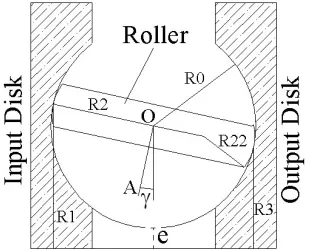
In each type of toroidal CVT, engine rotates input disk, and because of its contact with the roller, the roller revolves around its rotation axis (OA line). Similarly, the motion is transferred to the output disk. The variation of the roller tilt angle (g) leads to the variation of the distance between CVT rotation axis and the contact points. Thus, rotational speed of the roller and output disk change, and consequently, CVT speed ratio varies [10]. Figures 2 and 3 demonstrate a simple geometry of the half and full-toroidal CVT, respectively.
Varying q, the speed ratio range of half-toroidal CVT changes. If q=90°, half-toroidal CVT converts to full-toroidal one.
Figure 2. Simple geometry of half toroidal CVT
Figure 3. Simple geometry of full toroidal CVT
The geometry of toroidal CVT impacts the stress in the contact area, speed ratio range, its efficiency and therefore, the vehicle FC [11-13]. For instance, decreasing R22, the contact stress will increase, and vice
versa. On the other hand, in the upper and lower bounds of CVT speed ratio, the contact stress is maximal [12], and therefore speed ratio range is limited due to the limited strength of CVT elements. Accordingly, variation of R22 influences the speed ratio range of
toroidal CVT for a definite material of its elements. The contact type of the roller and the disks is a combination of rolling and sliding. If there is a pure rolling in the contact point, the speed ratio will be a function of the roller tilt angle and CVT geometry, as presented in equation (1)[10]:
out 1 0
r
in 3 0
ω R 1+ e R -cos(θ+γ)
S = = =
ω R 1+ e R -cos(θ-γ) (1)
In the pure rolling condition, there is no speed difference between CVT elements in the contact point. On the other hand, in order to create a tangential force which generates a torque around the rotation axes of the roller and output disk, there must be a shear stress in the oil film. If there is no speed difference between CVT elements in the contact point, shear stress will diminish. Consequently, in the pure rolling condition, torque isn’t transmitted from the input disk to the output one. Therefore, there must be a sliding motion between CVT elements. In this condition, speed ratio is not only a
function of the roller tilt angle and CVT geometry, but also of the percentage of the sliding. Hence, actual speed ratio of toroidal CVT is achieved by:
out 1 0
r in out
in 3 0
ω R 1+e R -cos(θ+γ)
S = =(1-Sp )(1-Sp ) =(1-Sp)
ω R 1+e R -cos(θ-γ) (2)
Since Sp and in Spout are small values, they can be
substituted with a slip coefficient (
Sp
) which is sum of them.3. EFFICIENCY OF TOROIDAL CVT
As stated, power train efficiency leaves a major effect on the vehicle FC. One of the primary parameters that impacts toroidal CVT efficiency, is the lubricating oil conditions in the contact area, which is a function of input torque, speed ratio and geometry [11, 12]. Therefore, using a model to simulate the contact between CVT elements is crucial. In this paper, a contact model presented in [11] is used. In this model, oil viscosity has been described as a function of its pressure and temperature [13]. Also, the value of shear stress in the oil film has been obtained. Integration of the shear stress over the contact area gives the tangential force which creates torque on the roller and the output disk. According to the model, power loss sources are the slip and spin motions between CVT elements in the contact area. Spin motion is due to the existence of the roller rotational speed in the direction normal to the contact area. The values of spin and slip losses are achievable by [12]:
in in out out
S Sp S Sp
SpinLoss=(M ω +M ω )n (3)
in in 1 1 out out 2 2 N
SlipLoss=(μ Sp R ω+μ Sp R ω )nF (4)
Applying the presented equations, CVT efficiency can be calculated as follows [13]:
Input Power-SpinLoss-SlipLoss η=
Input Power (5)
Because of the introduced power losses, CVT efficiency is lower than the conventional power trains. However, the main merit of CVT is its ability to change speed ratio continuously, enabling the engine to operate in its optimal rotational speed. Thus, totally CVT gives less fuel consumption compared to the conventional one.
4. SIMULATION MODEL OF POWERTRAIN
The vehicle required power can be calculated knowing its velocity and acceleration. It will be the model input. Also, the engine required power is achieved by:
required engine
transm ission
P
P =
h (6)
The transmission efficiency (htransm ission ) which is equal to hCVThFinal Drive, is a function of its input torque, speed ratio and rotational speed. In the first step, a rough estimation for it is considered and the engine required power is attained. Afterwards, according to the control algorithm which will be described in the next section, the engine rpm and therefore its exerted torque is achieved. Subsequently, CVT speed ratio is determined with regard to the desired vehicle speed and the engine rpm, and its efficiency is calculated as well. The engine power is calculated again. This procedure is repeated until CVT efficiency converges. The block diagram of the model is shown in Figure 4.
5. FUEL CONSUMPTION METHOD AND CONTROL ALGORITHM OF SPEED RATIO
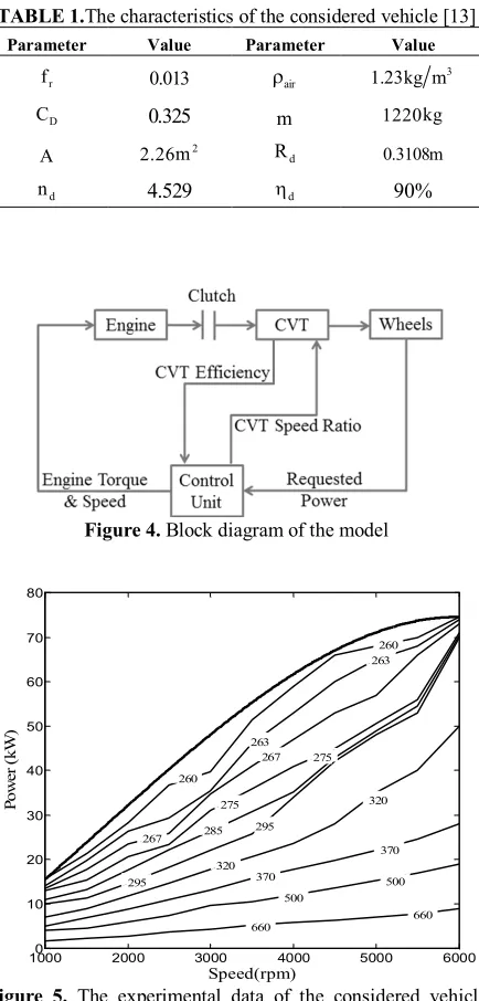
It is necessary to consider the vehicle motion in a driving cycle. It is assumed that the driver follows the driving cycle by regulating the pressure on the gas pedal. In the present study, the vehicle motion is considered in ECE driving cycle. The characteristics of the considered vehicle which are necessary to calculate FC are displayed in Table 1.
The experimental data of the engine brake specific fuel consumption (BSFC) is essential to calculate the vehicle FC. The experimental data of the considered vehicle’s engine is shown in Figure 5. These data are presented by the engine manufacturer.
The method of FC calculation is described and validated in [13]. In this method, it is assumed that CVT speed ratio control is on the base of minimizing the vehicle FC. In this control strategy, in each point of driving cycle, the required power of the engine is achieved. According to Figure 5, for any value of the engine required power, the engine rpm in which its BSFC is minimal is definite. Considering the vehicle speed, the power train speed ratio is adjusted to attain this rpm. One of CVT shortcomings is its limited speed ratio range [9]. Therefore, the control algorithm of the speed ratio may determine a speed ratio which cannot be created by toroidal CVT. If the requested speed ratio is larger than the upper bound of the power train speed ratio range, the same maximum achievable speed ratio will be assigned to the speed ratio, and the engine rpm varies to reach the rpm which creates the vehicle speed. Moreover, in case where the speed ratio is smaller than the lower bound of allowable range, power train creates
the desired speed ratio with the assistance of the clutch, similar to the conventional transmissions.
6. OPTIMIZATION OF CVT GEOMETRY
As mentioned in references [11-13], the toroidal CVT efficiency is a function of different parameters such as its geometry. Thus, increasing the power train efficiency, and therefore, decreasing the vehicle FC seems feasible through variation of CVT geometry. The most efficient geometries of half-toroidal and full-toroidal CVT were determined in [11, 12].
TABLE 1.The characteristics of the considered vehicle [13]
Value Parameter
Value Parameter
3 1.23kg m air
r 0.013
r f
1220kg
m
0.325 D
C
0.3108m d
R
2 2.26m A
90% d
h
4.529 d
n
Figure 4. Block diagram of the model
Figure 5. The experimental data of the considered vehicle engine
10000 2000 3000 4000 5000 6000
10 20 30 40 50 60 70 80
Speed(rpm)
Po
w
er
(k
W)
285
320
320
370
370 500
500
660 660
275 267 263
260
260 263
267
275
295
In these studies, optimum geometry was achieved for a specific value of input torque. Obviously, the input torque of the power transmission varies during driving cycle. Hence, in order to obtain an optimum geometry which is valid over the whole range of the engine operating region, optimization of it in a driving cycle is essential.
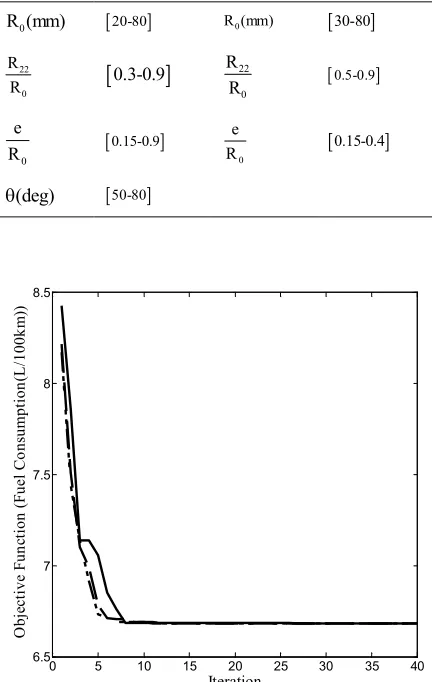
The optimization of full and half-toroidal CVT is implemented in ECE. To optimize CVT, Particle Swarm Optimization (PSO) method is utilized. PSO is one of the conventional optimization methods. Employing this method, the objective function converges rapidly and its global minimum is often achieved. In this method, some particles with specific position and velocity are assigned to the candidate solutions. At each iteration, their position and velocity are updated considering the position and velocity of the best solution. This algorithm is applied several times to reach the minimal value of the objective function. This method is thoroughly described in [11, 12]. The objective of the optimization is to minimize the FC of the vehicle equipped with each of full and half toroidal CVT. The optimization parameters and their range for each of full and half-toroidal CVT are shown in Table 2. These ranges are determined considering the conventional toroidal CVTs [11, 12].
The optimization process was implemented several times for the case of each full and half-toroidal CVT. In the optimization process, the initial values of the optimization parameters are chosen randomly. Therefore, there is a major concern about changing the optimization results due to variation of optimization initial values. Therefore, the optimization process was done several times to ensure that the optimization results are not dependent on the initial values of the parameters. Figures 6 and 7 show the variations of objective function during optimization for different initial values of optimization parameters, for the case of full and half-toroidal CVT, respectively.
As can be observed, there is a considerable reduction in the objective function during the optimization for both cases. The FC of the vehicle equipped with five-speed manual transmission is 12L/100km, while both optimizations result 6.68 L/100km. Therefore, a considerable fuel economy (44%) can be achieved through employing the optimized geometry of full or half-toroidal CVT. In addition, considering the initial values of the objective function during optimization reveals that, for some geometries of full-toroidal and half-toroidal CVT, the vehicle FC will be approximately 8.5L/100 km and 7.3L/100 km, respectively. Accordingly, the non-optimized geometries of both toroidal CVTs give a considerable fuel economy. It is due to the ability of the engine to operate in its fuel-optimal rpm through using CVT, while it is impossible for the case of using conventional transmissions.
TABLE 2.The optimization parameters and their range for each of half and full-toroidal CVT [11, 12]
Full-toroidal CVT Half-toroidal CVT
[30-80] 0
R (mm)
[20-80]
0 R (mm)
[0.5-0.9]
22
0
R R
[
0.3-0.9]
22
0 R R
[0.15-0.4]
0 e R
[0.15-0.9]
0
e R
[50-80]
(deg)
q
Figure 6.Variations of objective function during optimization of full-toroidal CVT
Figure 7.Variations of objective function during optimization of half-toroidal CVT
0 5 10 15 20 25 30 35 40 6.5 7 7.5 8 8.5 O bj ec ti ve F un cti on (F ue l C on su m pti on (L /100 km )) Iteration
Regarding Figures 6 and 7, for different initial values, the optimized value of objective function and optimized geometrical parameters for each case are the same. Therefore, the initial values of optimization parameters do not affect the optimization results. In addition, the value of optimal FC is the same for each case, and therefore, employing optimized full and half-toroidal CVT leads to similar fuel economy. The values of optimum parameters and optimized objective function for each case are presented in Table 3. These values are named normal parameters.
Using the optimized transmissions, the vehicle 0-100 km/h acceleration will be 9.3 and 9.2 s for the cases of half and full-toroidal CVT, respectively. While the acceleration of the vehicle equipped with five-speed manual transmission is 11.4 sec. Therefore, the vehicle acceleration improves about 18%. Additionally, the vehicle maximum speed for the case of using each CVT will be 185 km/h, which is equal to the case of manual transmission.
There is a concern about its ability to transfer maximum torque of the engine. As demonstrated in [7], the torque capacity of toroidal CVT is limited, because of the limited strength of its contact areas. Thus, the maximum stress in the contact areas for the application of the optimized geometries were calculated during transmitting the engine maximum torque through CVTs. It was found that the optimized geometries can transmit this torque without failure of CVTs in the contact areas.
7. EFFECT OF THE VEHICLE WEIGHT ON OPTIMAL POWER TRAIN
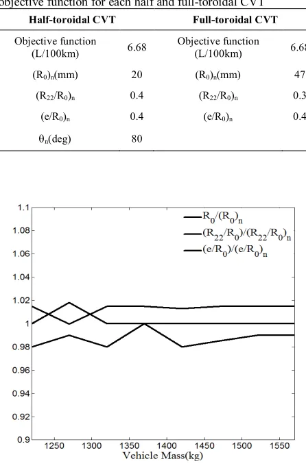
One of the main concerns about the power train optimization is that the optimal geometry may be a different value for different driving conditions, such as the vehicle weight. In this section, the effect of this parameter on the optimal geometry is investigated. The vehicle weight varies through daily use due to the change in the passenger number or cargo weight. Therefore, it is necessary to examine if the optimal geometry varies through variation of the vehicle weight. The gross weight of the considered vehicle is 1570 kg, while its curb weight is 1220 kg. In this section, the optimization process is implemented for different values of the vehicle weight in its allowable range. The optimization process was conducted several times for different values of the vehicle mass. In each case, the optimized geometry was achieved. These achieved parameters are divided by their normal value (shown in Table 3), and are shown in Figure 8 and 9.
As can be seen, the optimal geometry for full- toroidal CVT is approximately the same for different values of the vehicle weight, whereas its value for half- toroidal CVT varies through variation of the vehicle weight.
TABLE 3.The values of optimum parameters and optimized objective function for each half and full-toroidal CVT
Half-toroidal CVT Full-toroidal CVT
Objective function
(L/100km) 6.68
Objective function
(L/100km) 6.68
(R0)n(mm) 20 (R0)n(mm) 47
(R22/R0)n 0.4 (R22/R0)n 0.3
(e/R0)n 0.4 (e/R0)n 0.4
qn(deg) 80
Figure 8. Normalized values of full-toroidal optimum geometrical parameters for different values of the vehicle weight
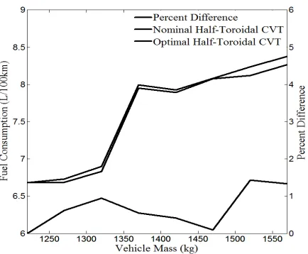
Figure 10. Vehicle FC versus its weight for the case of using the nominal half-toroidal CVT and the optimal one corresponding to different values of the vehicle weight
Besides, the curvature radius of the disks in half-toroidal CVT is practically fixed during variation of the vehicle weight. Consequently, the vehicle weight does not impact the optimum geometry of full-toroidal CVT. However, there is not an optimal geometry of half-toroidal CVT for different values of the vehicle weight. Nonetheless, in case of half-toroidal CVT, there may be no considerable difference in the values of FC between the case of using the optimal CVT for each values of the vehicle weight and the case of using the nominal one shown in Table 3. Figure 10 shows the variations of the vehicle FC versus its weight for the case of using the nominal half-toroidal CVT (shown in Table 3) and the optimal one corresponding to different values of the vehicle weight. Furthermore, the percentage difference between these cases is depicted in the figure.
As it is obvious, there is no significant difference (about 1%) in the FC values between the mentioned cases. For any values of the vehicle weight, FC of the vehicle equipped with the nominal CVT is slightly more than its value for the vehicle equipped with the optimal one. Consequently, the geometry for half-toroidal CVT proposed in Table 3 gives a reasonable fuel economy in different vehicle weights. It might be inferred from Figures 9 and 10 that, toroidal CVT geometry exerts no considerable effect on the vehicle FC. However, according to Figure 7, the variations of the vehicle FC due to the variations of CVT geometry are remarkable. Therefore, the sensitivity of the vehicle FC to the both CVTs is not trivial.
8. CONCLUSION
This study aimed to optimize full and half toroidal CVT in ECE driving cycle, and to examine the effect of the
vehicle weight on the optimal power train. Some results were achieved:
· A remarkable fuel economy (44%) can be attained through employing each of the optimized full and half-toroidal CVT.
· There is no significant difference between the optimal full-toroidal CVT geometries achieved for the case of different vehicle weights, whereas the optimal geometries for half-toroidal CVT are different.
· The fuel consumption of the vehicle equipped with the nominal geometry of half-toroidal CVT is close to its value for the case of using the optimal one. The difference between them is only 1%. Therefore, similar to full-toroidal CVT, there is a specific geometry for half-toroidal one which gives a considerable fuel economy for different weights of the vehicle.
9. REFERENCES
1. Ebrahimi, R. and Mercier, M., "Experimental study of performance of spark ignition engine with gasoline and natural gas", International Journal of Engineering, Vol. 24, (2010) 65-74.
2. Yousufuddin, S. and Masood, M., "Effect of ignition timing and compression ratio on the performance of a hydrogen–ethanol fuelled engine", International Journal of Hydrogen Energy, Vol. 34, No. 16, (2009), 6945-6950.
3. Dutta-Roy, T. and Zhang, N., "Effect of a half-toroidal continuously variable unit on the dynamics of a complete powertrain: A parametric free vibration analysis", Proceedings of the Institution of Mechanical Engineers, Part D: Journal of Automobile Engineering, Vol. 218, No. 5, (2004), 471-484. 4. Yu, H.-S., Zhang, J.-W. and Zhang, T., "Control strategy design
and experimental research on a four-shaft electronic continuously variable transmission hybrid electric vehicle", Proceedings of the Institution of Mechanical Engineers, Part D: Journal of Automobile Engineering, Vol. 226, No. 12, (2012), 1594-1612.
5. Jacod, B., Venner, C. and Lugt, P., "A generalized traction curve for ehl contacts", Journal of Tribology, Vol. 123, No. 2, (2001), 248-253.
6. Newall, J. and Lee, A., "Measurement and prediction of spin losses in the ehl point contacts of the full toroidal variator", Tribology Series, Vol. 43, No., (2003), 769-779.
7. Attia, N. A., Datong, Q., Wankai, S. and Huaying, L., "A parametric study on the contact stress of half toroidal continuously variable transmission", Journal of Chongqing University, Vol. 2, No. 2, (2003).
8. Machida, M. and Murakami, Y., "Development of the half toroidal cvt powertors unit", Journal of NSK Technology, Vol. 9, (2000), 15-26.
9. Tanaka, H. and Machida, H., "Half-toroidal traction-drive continuously variable power transmission", Proceedings of the Institution of Mechanical Engineers, Part J: Journal of Engineering Tribology, Vol. 210, No. 3, (1996), 205-212. 10. Carbone, G., Mangialardi, L. and Mantriota, G., "A comparison
11. Delkhosh, M., Foumani, M. S., Boroushaki, M., Ekhtiari, M. and Dehghani, M., "Geometrical optimization of half toroidal continuously variable transmission using particle swarm optimization", Scientia Iranica, Vol. 18, No. 5, (2011), 1126-1132.
12. Delkhosh, M. and Foumani, M. S., "Multi-objective geometrical optimization of full toroidal cvt", International Journal of Automotive Technology, Vol. 14, No. 5, (2013), 707-715. 13. Delkhosh, M. and Foumani, M. S., "Optimisation of full-toroidal
continuously variable transmission in conjunction with fixed
ratio mechanism using particle swarm optimisation", Vehicle System Dynamics, Vol. 51, No. 5, (2013), 671-683.
14. Akbarzadeh, S. and Zohoor, H., "Sensitivity analysis of torque transmission efficiency of a half-toroidal cvt", SAE Paper, (2006), 01-1304.
15. Newall, J. P, Cowperthwaite, S., Hough, M. and Lee, A., "Efficiency modelling in the full toroidal variator: Investigation into optimisation of ehl contact conditions to maximize contact efficiency", Tribology and Interface Engineering Series, Vol. 48, (2005), 245-255.
Modelling and Optimization of Toroidal Continuously Variable Transmission in ECE
Driving Cycle
M. Delkhosh, M. SaadatFoumani
Department of Mechanical Engineering, Sharif University of Technology, Tehran, Iran
P A P E R I N F O
Paper history:
Received 27 April 2013
Received in revised form 22 May 2013 Accepted 20 June2013
Keywords:
Continuously Variable Transmission Toroidal CVT
Fuel Consumption Optimization Vehicle Weight
هﺪﯿﮑﭼ
ﻪﻨﯿﻬﺑفﺪﻫ،ﺶﻫوﮋﭘﻦﯾارد ﻪﺘﺳﻮﯿﭘترﺪﻗلﺎﻘﺘﻧاﻢﺘﺴﯿﺳيزﺎﺳ
) CVT ( فﺮﺼﻣﺶﻫﺎﮐفﺪﻫﺎﺑهﺮﺒﻨﭼمﺎﻤﺗوهﺮﺒﻨﭼﻒﺼﻧ
نآ ﻪﺑﺰﻬﺠﻣيوردﻮﺧﺖﺧﻮﺳ يﺮﻬﺷﻞﮑﯿﺳرد ﺎﻫ
ECE ﺖﺳا . نآهدزﺎﺑﻦﯿﯿﻌﺗياﺮﺑ لﺪﻣﮏﯾاﺪﺘﺑا،رﻮﻈﻨﻣﻦﯾاياﺮﺑ ﺎﻫ
ﯽﻣﯽﻓﺮﻌﻣ دﻮﺷ . ﮏﯾ ﺖﺧﻮﺳفﺮﺼﻣندﺮﮐﻪﻨﯿﻤﮐيﺎﻨﺒﻣﺮﺑترﺪﻗلﺎﻘﺘﻧاﻢﺘﺴﯿﺳﻞﯾﺪﺒﺗﺖﺒﺴﻧﺮﯿﯿﻐﺗياﺮﺑﯽﻟﺮﺘﻨﮐﻢﺘﯾرﻮﮕﻟا
ﯽﻣﻪﺋاراوردﻮﺧ ﯽﻣﻪﺋاراﺖﺧﻮﺳفﺮﺼﻣﻪﺒﺳﺎﺤﻣلﺪﻣو،دﻮﺷ
دﻮﺷ . ﻢﺘﯾرﻮﮕﻟاﮏﻤﮐﻪﺑترﺪﻗلﺎﻘﺘﻧاﻢﺘﺴﯿﺳودﺮﻫﺲﭙﺳ
تارذﯽﻫوﺮﮔ )
PSO ( ﯽﮔﺪﻨﻧارﻞﮑﯿﺳردوردﻮﺧﺖﺧﻮﺳفﺮﺼﻣندﺮﮐﻪﻨﯿﻤﮐفﺪﻫﺎﺑ ECE
ﻪﻨﯿﻬﺑ ﻪﺳﺪﻨﻫ،هﺪﺷيزﺎﺳ
نآ ﻪﻨﯿﻬﺑ ﯽﻣﺖﺳﺪﺑ ﺎﻫ ﺪﯾآ
. ﯽﻣﻞﺻﺎﺣﻪﺠﯿﺘﻧﻦﯾا ﻪﻨﯿﻬﺑﮏﻤﮐﻪﺑ،ﻪﮐدﻮﺷ
ﻞﺑﺎﻗﯽﻬﺟﻮﺗﻞﺑﺎﻗﺖﺧﻮﺳفﺮﺼﻣﺶﻫﺎﮐ،يزﺎﺳ
ﺖﺳد ﺖﺳاﯽﺑﺎﯾ . عﻮﻧودﺮﻫﻪﻨﯿﻬﺑﻪﺳﺪﻨﻫيوروردﻮﺧنزوتاﺮﺛا،ﻪﻣادارد CVT
ﯽﻣﯽﺳرﺮﺑ دﻮﺷ . ﺖﺳﺪﺑﻪﺠﯿﺘﻧ ﻦﯾا
ﺎﯾزﺮﯿﺛﺎﺗوردﻮﺧنزو،ﻪﮐﺪﻣآﺪﻫاﻮﺧ ﻪﻨﯿﻬﺑﻪﺳﺪﻨﻫيوريد
CVT مﺎﻤﺗ ﻪﻨﯿﻬﺑﻪﺳﺪﻨﻫنزوﺮﯿﯿﻐﺗﺎﺑﻪﮐﯽﻟﺎﺣرد،دراﺪﻧهﺮﺒﻨﭼ
دﺮﮐﺪﻫاﻮﺧﺮﯿﯿﻐﺗهﺮﺒﻨﭼﻒﺼﻧعﻮﻧ .
![Figure 1. A typical full toroidal CVT [15]](https://thumb-us.123doks.com/thumbv2/123dok_us/235071.2018152/2.595.342.512.575.740/figure-typical-toroidal-cvt.webp)