R E S E A R C H
Open Access
Nanoelectronic COupled Problems
Solutions: uncertainty quantification
for analysis and optimization
of an RFIC interference problem
Piotr Putek
1,2*, Rick Janssen
3, Jan Niehof
3, E. Jan W. ter Maten
1, Roland Pulch
2, Bratislav Tasi´c
3and
Michael Günther
1*Correspondence:
[email protected] 1Bergische Universität Wuppertal, Wuppertal, Germany
2Ernst-Moritz-Arndt-Universität Greifswald, Greifswald, Germany Full list of author information is available at the end of the article
Abstract
The FP7 project nanoCOPS (the 7th Framework Programme project Nanoelectronic COupled Problems Solutions) derived new methods for simulation during
development of designs of integrated products. It has covered advanced simulation techniques for electromagnetics with feedback couplings to electronic circuits, heat and stress. It was inspired by interest from semiconductor industry and by a simulation tool vendor in electronic design automation.
Due to the application of higher frequencies and the continuous down-scaling process, there is a higher probability of unforeseen interactions between different domains of a Radio Frequency Integrated Circuit (RFIC), which can lead to the variability of the output performance functions. Since these undesired phenomena ought to be investigated in the early phases of the integrated circuit (IC) design, in this work we formulate the robust optimization problem in terms of the expectation and the standard deviation values under the uncertainties of material parameters.
Therein, the statistical information included in the multi-objective functional can be provided by a response surface model. For this purpose the Stochastic Collocation Method (SCM) combined with Polynomial Chaos Expansion (PCE) has been used. The reason for analyzing the variability of the Electromagnetic Interference (EMI) is, on the one hand, to quantify the uncertainty in an integrated Radio-Frequency
Complementary Metal-Oxide Semi-Conductor (RFCMOS) transceiver design, and, on the other hand, to improve this design in a robust sense. We have illustrated our methodology for an integrated Radio-Frequency Complementary Metal-Oxide Semi-Conductor (RFCMOS) transceiver design.
Keywords: Floor-plan modeling; Isolation grounding; Polynomial chaos expansion; Stochastic collocation method; Uncertainty quantification; Robust design
optimization; Sobol decomposition; Variance-based and local sensitivity analysis
1 Introduction
Nowadays the computational electromagnetic (CEM) modeling methods are the integral part of the advanced tools for electromagnetic compatibility (EMC) problems of inte-grated circuits (ICs), encountered in engineering practice [2]. In contrast to the
tional EMC product testing, which are both time-consuming and expensive, computa-tional modeling and simulation offer more flexibility in design modification and are po-tentially faster and cheaper [39]. They can be applied to resolve a broad range of real life problems, including interference issues and coupling effects in modern mixed-signal and radio frequency integrated circuits. The latter has become more and more impor-tant with the continuous integration process of RF, mixed signal and digital blocks on a single die, which is additionally combined with observable trends on semiconductor mar-ket to apply higher frequencies for accommodating higher data rates [20]. These trends towards miniaturization of RFIC allows primarily for easier implementation of multiple functions in a compact unit, which implies also substantial reductions in product cost. In fact, the complexity poses many challenges in the integration process of various subsys-tems, such as the so-called aggressors (the noisy blocks), the victims (the sensitive part, affected by noise) and other intellectual property (IP) blocks to ensure their proper and interference-free operation [15]. Additionally, provisions should be made at the influence of the miniaturization on the failure probability associated with yield loss due to defects, faults, process variations and design issues [37]. In fact, the statistical variations in input parameters, originating from manufacturing tolerances of industrial processes, may re-sult in a thermal destruction of devices due to thermal runaway [30,32]. In this respect, taking the input statistical variations into account in modeling allows for providing the predictable and reliable RFIC simulations. Moreover, unintended RF coupling, caused by industrial imperfections and miniaturization due to the scaling-down process, could sig-nificantly downgrade the quality of products and their performance or even be dangerous for safety of both environment and the end-users [8]. Thus, to meet the stringent design specification requirements for electromagnetic compatibility standards [4] such as speeds, bandwidth, noise margin crosstalk, etc., the ICs designers have to be aware of interference issues caused by high-frequency phenomena and randomness involved in the manufac-turing process. Considering these phenomena at early design stages allows for avoiding expensive re-spins and to reduce iterations in the time-to-market cycle.
Therefore, the structured methodology is needed to model the adverse effects caused by the manufacturing process using polynomial chaos expansion combined with the stochas-tic collocation method [43–46] for analysis of the EMC problem of integrated circuits. Here, we focus more on the new application of the methodology mainly developed in [32,
providing detailed insights on the floorplanning and grounding strategy as well as new results for the variance-based and the local sensitivity analysis.
The paper is organized as follows. Section2overviews the methodology developed and used for modeling and simulation of an integrated RFCMOS transceiver for automotive applications, that is the so-called floorplan modeling and isolation strategy. Section3, in turn, considers the benefits of the PCE-based stochastic collocation methods applied for solving the random-dependent Differential-Algebraic Equations (DAEs) and additionally provides the results for the variance-based and the local sensitivity analysis. Section4deals with the robust optimization problem, which definition includes the statistical moments, used as cost functional. Section5gives some achievements obtained during the project with respect to reliable RFIC isolation. And finally, in Sect.6we briefly summarize our paper including remarks and future work on this research.
2 Methodology for deterministic modeling
In this work, we analyze a design of an integrated RFCMOS automotive transceiver de-sign, depicted on Fig.1, which is treated in our study as a test case. Thus, we consider a fully functional chip [20], which, in particular, is comprised of four main subsystems such as (i) an analog-to-digital converter (ADC), (ii) the receiver and power amplifier (RxPA), (iii) the crystal oscillator and local oscillator (XoLO) and (iv) the digital part. Therein, for the noise generation, which affects proper functioning of other systems, the so-called aggressor units such as digital logic, digital input/output (IO) systems (IOs), clock gener-ation circuits, etc. are responsible. Due to the complexity of the used test case, the proper methodology needs to be used in order to analyze the EMC problems. Within this con-text, the proper operation of devices and circuits in electromagnetic environment can be achieved by applying appropriate shielding strategy together with controlled low emission of noise sources. Therefore, to take into account varied type of coupling in our modeling approach, the special methodology, proposed in [20] and further developed by [15], has been applied. This methodology makes use of an overall model of the RF product, con-sisting of the following key elements:
• On-chip: domain-regions, padring, sealring, splitter cells, substrate effects (including deep-Nwell and Pwell regions).
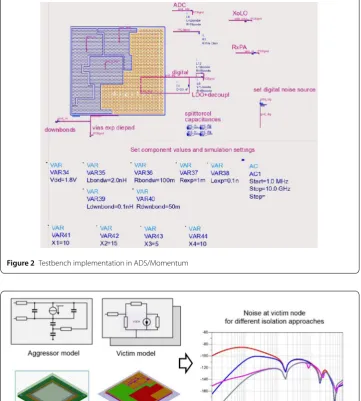
Figure 2Testbench implementation in ADS/Momentum
Figure 3Testbench example and results [15]
• Package: ground and power pins, bondwires/downbonds, exposed diepad connection. • Printed Circuit Board (PCB): ground plane and exposed diepad connections.
2.1 Mathematical modeling for an RFCMOS automotive test case
In our work, to avoid computationally expensive simulations of the fully three-dimensional model of RFIC [39,48], the Equivalent Circuit Model (ECM) with the appropriate floor-plan modeling and isolation strategy has been used. More specifically, the ECM has been created based on the simulation of a chip architecture using the Advanced Design System (ADS)/Momentum software from Keysight Technologies [18]. Hence, for the solution of systems of partial differential equations the Methods of Moments (MoM) [6] has been em-ployed, where the concept of Green functions is explored to model the proper behavior of the substrate [12].
Therein, the interaction of the ICs with their physical environment has been consid-ered by solving an integral formulation of the time-harmonic partial differential equations (PDEs), derived from Maxwell’s equations
∇ ·(θ)∇V(θ) + iωA(θ)= –ρ˜(θ), (1a)
ν(θ)∇ × ∇ ×A(θ) = J(θ) +ω2(θ)
A(θ) – i∇V(θ)
ω
, (1b)
∇ ·A(θ) + iωkV(θ) = 0, (1c)
∇ ·J(θ) + iωρ˜(θ) = 0, (1d)
which have been equipped with suitable initial and boundary conditions, in the commer-cial software Momentum [18]. Here, the variable i is defined by i =√–1,kdenotes a scaling factor, whileρ˜is the charge density. In the above system (1a)–(1d),Vdenotes the electric scalar potential, while A is the magnetic vector potential. The location in space is de-noted by r andθ:= (r,f);ω= 2πf refers to the angular velocity withf being the frequency. The real-valued functions(r) andν(r) describe the permittivity and the reluctivity, re-spectively. We have carried out our simulations in a time-harmonic regime that yields accurate electromagnetic simulation performance at radio frequencies for the geometri-cally complex and electrigeometri-cally small designs. Their outcome in the form of S-parameters, generated for general planar circuits, contains sufficient amount of information in order to characterize each individual component, used in the ECM. The ADS tool of Momen-tum, which is advantageous in describing the electrical device characteristics, gives the opportunity to model the behavior of RF passive component by a frequency independent lumped model [18]. Thus, this lumped model can be further explored in both the direct and optimization problems [28,29].
For this purpose, based on the conducted simulations of (1a)–(1d) and the proper floor-planning with grounding strategies, an equivalent circuit model of the IC and package has been developed [20], depicted in Fig.2. It is supposed to be the lumped model of the 3D model, shown in Fig.1. When for the mathematical modeling of the EMC the flux/charge oriented Modified Nodal Analysis (MNA) has been used, the time-harmonic structured DAE, written in a compact way, is given by
iωCp(k)xp(k),f+ Gp(k)xp(k),f= s(f), k= 1, . . . ,K, (2)
pa-rameter of interest. s(f)∈Cnrefers to an input vector which is determined by the
inde-pendent current and voltage sources. The matrices C(p), G(p)∈Cn×ndescribe the lumped
memory-less and memory elements, respectively, which depend only on the parameters
p, whilencorresponds to the total number of MNA variables [11,13,36].
Specifically, in our work we are particularly interested in how the digital domain influ-ences other subsystems. To this end, we define for a (scalar) cross-domain coupling the transfer function as in [5]
G(ω) =|Y|
|X|=:H(iω), φ(ω) :=φY–φX=arg
H(iω), (3)
when considering a complex harmonic system with a sinusoidal component of|X|, an an-gular frequencyωand a phaseφ:=arg(X) as an input to a linear time-invariant system and then its corresponding output as|Y|andφY:=arg(Y). The specific definitions of
ob-jective functions to be included in the optimization procedure will be given in Sect.4.1. More information on the extraction of the equivalent circuit model from the PDEs can be found, e.g., in [15,20]. For the needs of this study, we also briefly recall some basic con-cepts of the EMC extraction that are required for stochastic modeling. It will be a topic of Sects.2.2and2.3.
2.2 Testbench model of the integrated circuit
As the first step, an initial floorplan model, describing the interaction between individual IP blocks/substrate domains via the substrate and well structures, is created. If present, also the connection of the backside of the die is included by taking the vertical substrate noise propagation path into account. Each IP block is represented by a single port, rep-resenting substrate connections. Such a first-order model can be created with a number of commercially available EM simulators. Initially, a rough estimate of the technology pa-rameters can be sufficient (e.g., substrate conductivity). The output (either S-papa-rameters or lumped circuit components) is then included in the simulation testbench shown later. In addition in finding the optimal relative placement of the IP blocks and the spacing be-tween them, this model can also be used to study the impact of, e.g., type of substrate (bulk vs. silicon-on-insulator), doping levels (lowly-doped vs. highly-doped), backside connec-tion (soldered vs. glued), etc. Figure3shows an example floorplan model indicating the typical complexity (number of used substrate/ground domains) of the analyzed design.
The aggressor current, representing the switching activity of, e.g., the digital block, pro-duces a bounce on the supply and ground nodes due to the finite impedance of the sup-ply/ground network. This noise then couples to the victim through the substrate repre-sented by the floorplan model. The values of the well junction capacitances representing the well structures are determined by the technology, the aggressor area and the design style (e.g., presence of Deep N-Well). In addition, currents through the bondwires can also inductively couple to the bondwires of the victim circuit. On-chip voltage regulators and decoupling capacitances have an impact on the coupling and need to be included in the model, either as S-parameters or by a simplified circuit model. Typical aggressors include: digital logic, digital IOs, clock generation circuits, a digital-to-analog converter (DAC) and ADC.
voltage-controlled current source, or an ideal operational amplifier with a simplified feedback cir-cuit. In this case, in addition to the substrate noise rejection properties of the circuit, the noise coupling to the amplifier input can be included in the model. Finally, when the de-sign of the victim block is complete, an S-parameter file, containing the relevant terminals (e.g. substrate and sensitive input), should be generated by the IP designer for inclusion in the interference testbench. Typical victims are: sensitive RF tuners, analog IOs, ADC, voltage controlled oscillators (VCO), etc.
Similar to victim IP models, different levels of abstraction are used to incorporate the package coupling effects in the analysis. Again, at early stages, a very simple model could be useful. Lumped inductances with estimated values based on expected lengths of bond-wires [3] and leads are added to the testbench. Later, it can be extended with estimates of mutual inductances and capacitances, based on previous designs or simple models. At this stage, a concurrent optimization of the floorplan and the IO ring takes place. Finally, when the IO ring and pin assignment is fixed and the package choice is finalized, the full-package model can be included in the test bench for a more accurate prediction of inductive and capacitive effects. The models of individual IP blocks, the floorplan and the package are combined in a single testbench, which is used to investigate the total effect of all imple-mented isolation measures (see Fig.3).
2.3 Verification of the applied methodology
Validation of the methodology has been reported in [20]. The same relative effect of 8– 9 [dB] by adding the downbonds for the ground connections has been observed in both simulated transfer values, as well as in spur measurements of packaged IC samples.
A more direct validation approach includes comparison of the voltage transfer between different ground domains in the design. As can be seen from Fig.4, the general trends are predicted within a few [dB] for various combinations, indicating that the main coupling paths, as well as the parameter estimates, are properly incorporated in the model [15].
3 Stochastic modeling and uncertainty quantification
In the model (2), we replace physical parameters p∈Π⊆Rqby independent random vari-ables p :Ωpr→Πon some probability space (Ωpr,A,P) to quantify uncertainties. Letpi
fori= 1, . . . ,qbe a random variable with a traditional probability distribution like uniform distribution or Gaussian distribution, for example. The solution of the system (2) becomes a random field, i.e., each component of the solution represents a function depending on the random variables p for fixed frequencyf ∈Fin some frequency rangeF⊆R. The chosen physical parameters belong to the four different parts (a)–(d) of the functional chip specified in Sect.2.1.
3.1 Polynomial chaos expansion
Letz:Π→Rbe a measurable function depending on the random variables. The associ-ated expected value reads as
E[z] =
Ωpr
zp(χ)dP(χ) =
Π
z(p)ρ(p) dp (4)
using the probability density function ρ:Π→R. The variance is defined as usual by
Var[z] =E[(z–E[z])2]. A functionzis square-integrable, if the expected valueE[z2] exists.
Moreover, it holds thatE[ΦiΦj] =δijwith the Kronecker delta symbol.
Any square-integrable function owns a unique Polynomial Chaos (PC) expansion, see [44]. Lety:Π×F→Rbe a function depending on the domainF as well as the random variables inΠ. Ifyis always square-integrable with respect to the random vari-ables, it holds that
y(p,f) =
∞
i=0
vi(f)Φi(p) for eachf (5)
with the coefficientsvi:F→Rand the basis polynomialsΦi:Π→R. Moreover, it holds
thatE[ΦiΦj] =δijwith the Kronecker delta symbol. The convergence is in the mean-square
sense in the probability space. The coefficients become frequency-dependent functions and are defined by the inner products
vi(f) =E
y(·,f)Φi(·)
fori∈N0and eachf. (6)
Consequently, we consider the PC expansion (5) pointwise in the frequency parameter. In practice, just a finite number of terms can be handled, which implies a truncated expansion
˜
y(p,f) =
N
i=0
vi(f)Φi(p) for eachf (7)
as an approximation of the exact function (5). Often all polynomials up to some total de-greedare included. Sinceqindependent random variables are given, the number of basis polynomials becomesN+ 1 = (dd+!qq!)!. Furthermore, assuming thatΦ0 = 1, the expected
value and the variance are given by
Ey(·,f)=. Ey˜(·,f)=v0(f) and Var
y(·,f)=. Vary˜(·,f)=
N
i=1
vi(f)2 (8)
3.2 Pseudo-spectral approach
In our work, we apply a stochastic collocation method for the approximation of the co-efficient functions in the truncated expansion (7). Therein, the probabilistic integrals (4) in (6) are computed approximately by a multidimensional quadrature rule, which is spec-ified by a set of nodes{p(1), . . . , p(K)} ⊂Πand a set of weights{w1, . . . ,wK} ⊂R. Thus, the
approximations read as
˜
vi(f) = K
k=1
wky
p(k),fΦi
p(k) for eachf (9)
andi= 0, 1, . . . ,N. Specifically, the Stroud formula of order 3, see [30,32], is used in a nu-merical quadrature. The number of nodes becomesK= 2q, which is the minimum num-ber required for a polynomial exactness of degree 3. The associated weights are all positive and identical, i.e.,wk=21q for allk, which represents an advantageous property with
re-spect to error propagation. In our application, we consider the solution of the model (2) with random parameters. Thus, the evaluation of (9) requires the numerical solution ofK
deterministic systems (2) including boundary conditions, one system for each parameter realization.
3.3 Sobol decomposition and variance-based sensitivity analysis
Given a functionz:Π →Rdepending on parameters p, we are interested in sensitivi-ties. Local sensitivities are given by the partial derivatives of the deterministic parameter-dependent functionzprovided that the function is smooth.
Global sensitivities quantify the dependence on the random variables p in the probability space. The global sensitivity coefficients can be defined by the PC expansion of a square-integrable random variable, see [24,25,38]. We define the index sets
Ij={i∈N0:Φiis non-constant inpj} forj= 1, . . . ,q,
which represent the sets of polynomials depending on a particular random variable. Let (vi)i∈N0 be the PC coefficients of the functionz. A truncation of the index sets and the
approximation (8) of the variance generate an approximation of the global sensitivity co-efficients, i.e.,
Sj=
i∈ ˜Ij
v2i
N
i=1
v2i
forj= 1, . . . ,q (10)
with finite index setsIj˜ =Ij∩ {0, 1, . . . ,N}. These approximations implies the bounds 0≤Sj≤1 for eachj and 1≤S1+S2+· · ·+Sq≤q. (11)
A random variablepjexhibits a relatively strong impact on the outputz, if it holds that
Sj≈1. IfSj≈0, it is not significant. In our application, a functiony:Π×F→Ris given.
Thus, we apply the above approach pointwise forf ∈F. The total effect sensitivity co-efficients (10) become functionsSj:F→Rforj= 1, . . . ,q. The SCM yields
Moreover, differentiating (7) with respect topjyields∂y˜/∂zjat any value of z defined as
∂˜y ∂zj
zj=zj
=
N
n=0
vi
∂Φi
∂zj
∂z ∂pj
, j= 1, . . . ,q. (12)
Thezjth mean sensitivity is obtained by integrating over the whole parameter space [44].
4 Optimization under noise emission and uncertainties
The problem of the empirical design of the cross-domain coupling on RFIC under uncer-tainties based on the Sobol decomposition [38] has been has carried out in paper [48]. Within the nanoCOPS project (http://fp7-nanocops.eu/), the variance-based and the lo-cal sensitivity analysis based on the PCE surface response model and the adjoint variable method has been explored in many engineering fields. For instance, in [29] the forward stochastic problem of the RFIC isolation under uncertainties has been studied in [28]. In works [30–32], in turn, the PCE-based stochastic collocation methods has been applied for the UQ analysis and the robust shape/topology optimization of the power transistor device under material and geometric uncertainties. Additionally, in the paper [23] the stochastic inverse problem has been investigated. Here, we focus mainly on presenting the robust framework, tailored for the application of the electromagnetic interference variability on the RFIC, which is partially based on the preliminary results achieved in [29].
4.1 Objectives
In the ECM, the activity of the digital domain is represented by a current sourceIcore,
which acts as an aggressor, shown on Fig.6. To investigate the impact of noise generated by the aggressor on victims part such as RxPA, XoLO and ADC, based on (3) and under assumption of the first approximation by means of two-ports consisted ofR,Lelements, the cross-coupling functions are defined as the frequency response in the following form
y1(p,f) =CplADC(p,f):= 20log|
gnd_adc – PCBgnd|
|Vdd_dig – gnd_dig|, (13a)
y2(p,f) =CplXolo(p,f):= 20log |
XOLOgnd– PCBgnd|
|DigitalVdd– Digitalgnd|, (13b)
y3(p,f) =CplRx(p,f):= 20log
|RxPAgnd– PCBgnd|
|DigitalVdd– Digitalgnd|. (13c)
These functions allow for measuring the influence of emitted noise into the functioning of RxPA, XoLO and ADC subsystems.aAdditionally, the respecting bondwires, downbonds
and diepad vias, shown on Fig.6, are assumed to be random-dependent in our stochastic approach, i.e., z(p) = (z1(p1),z2(p1),z3(p1),z4(p1)). Because of the application of the
time-harmonic analysis, the particular random parameters are represented by impedanceszj,
which are explained more precisely in Sect.5.
for-mulated as follows
J(p,f) = 1 2
3
i=1
wiyi(p,f)
2
, (14)
where the prescribed weight are assumed to be defined aswi= 0.5,i= 1, . . . , 3. However,
in practical computation, presented in the next section, the response functiony1(p,f) had
to be excluded from the optimization due to its totally insensitivity with respect to even the relatively large input variations [29].
4.2 Robust formulation
In the conventional optimization, it is assumed, for simplicity, that the parameters of in-terest are treated as deterministic variables. This, in turn, can lead to an optimal con-figuration, which is very sensitive to the variation of the nominal parameters [47]. From this perspective, there is a need to take into account uncertainties of material and/or geo-metric parameters, including excitation term that comes from manufacture imperfection, during the optimization process. To solve this problem, we propose to apply the robust framework [40], invented by the Japanese engineer Taguchi. This allows for providing an optimal design of the RFIC, which is insensitive to variations of random parameters as well as robust versus the noise generated by the aggressors.
In the proposed robust formulation [32,34,42], an optimization problem constrained by stochastic DAEs (2) read as
inf
z(p)E
J(p,f)+η
VarJ(p,f) (15a) s.t. iωCp(k)xp(k),f+ Gp(k)xp(k),f= s(f), k= 1, . . . ,K, (15b)
zmax≤z≤zmin, = 1, . . . ,P, (15c)
where the expectation valueE(·) and the varianceVar(·) are defined by (8) and 3≤η≤6 is the prescribed coefficient, e.g, for the six-sigma methodη= 6 [16]; z(p) is a vector of opti-mized parameters, while zmaxand zmindenote their box constraints, respectively. In the
case of any gradient optimization method used to find the solution of the problem (15a)– (15c), the derivative of the robust functional (15a) is required. The next section includes the brief recall of basic concepts of some ‘deterministic’ sensitivity analysis techniques.
4.3 Sensitivity analysis for gradient calculation
The sensitivity analysis allows for investigating the influence of inputs perturbation into the variation of output performance functions, i.e., the tolerance analysis. Its application can be further extended to the problems of network synthesis, which is based on the op-timization of the assumed network performance function, e.g., expressed by the robust functional (15a).
The perturbation technique belongs to the simplest sensitivity techniques, in which the first-order derivative is represented by a centered difference approximation for a fixedkth grid pointpm:=p(mk),m= 1, . . . ,Mby [10]
ˆ
x(p,f)≡∂x(p,f)
∂pm
.
=x(pm+h,f) – x(pm–h,f) 2h +O
Here,h> 0 is a small value and the notationO(·) corresponds to the order of error in the used approximation. The disadvantages of this technique are the computational complex-ity and an numerical error related to the assumed approximation.
The direct sensitivity analysis, also known as the incremental model technique [5,19], which can be obtained by differentiating (15b) as follows
iωC(p)xˆ(p,f) + G(p)xˆ(p,f) = –iω∂C(p) ∂pm
x(p,f) –∂G(p)
∂pm
x(p,f)
jpm(f)
. (17)
This method, however, requires first forming jpm(f), i.e., the right-side of (17) and then
solving the created system of equationsMtimes including once analysis of the original problem (15b) in order to evaluatexˆ(p,f). Therefore, this procedure is computationally expansive, even when the LU decomposition is re-used. To improve its numerical effi-ciency it can be combined with the adjoint variable method [21]. It allows for calculating derivative of the objective functionF(x(p,f)) in an efficient way by
∂F(x(p,f))
∂pm
:= x(p,f)jpm(f), m= 1, . . . ,M, (18)
where the adjoint variable vector x(p,f) is the solution to the adjoint model, defined as iωC(p)x(p,f) + G(p)x(p,f) = (∇xF) (19)
with∇xFdenoted as a derivative ofF(x(p,f)) with respect to the state variable x(p,f)
eval-uated at the current solution x(p,f) = x∗(p,f) [22]. In such a case, this technique becomes a discrete counterpart of a continuous adjoint sensitivity analysis based on Tellegen’s the-orem [5,41] or based on the variational approach [7,14,26].
Moreover, in case of the robust formulation, the above-described sensitivity techniques can be combined with the PCE (6), (7) and (8) in order to calculate the derivative of mean and of standard deviation [1,31,32]. Within this context, in the nanoCOPS project, the variance-based sensitivity analysis (10) has been used in [34] for the solution of a shape optimization problem. In the current work, based on results achieved in [28], the so-called mean gradient sensitivity analysis (12) has been applied to approximate the derivative of the robust functional.
5 Results for numerical experiment and discussion
For the purpose of the optimization of the cross-domain coupling under uncertain param-eters within a real-life RFIC problem, we replace the EMC, shown on Fig.1by the lumped model depicted on Fig.6. Furthermore, this model has been implemented and simulated in Momentum. The implementation and deterministic simulation have been shown on Figs.2and5, respectively. In our equivalent lumped model, the digital ‘dirty’ part, that is the aggressor, is represented by a current modelIcorewith frequency ranging from 1 MHz
to 10 GHz. The resistances treated in the lumped model as deterministic variables are defined in the following way: R1= 13.2 [], R2= 13.2 [], R3= 22.7 [], R4= 5.6 [],
R12= 77 [],R13= 332 [],R23= 217 [],R24= 96 [] andR34= 130 []. The nominal
Figure 5Exemplary deterministic simulations of the EMC with the cross-domain transfer functions CplRx(f), CplXolo(f) and CplADC(f)
Figure 6Chip architecture with domains indicated, testbench model for an RFIC isolation problem [8]
Table 1 Chosen values for the deterministic elements of the EMC model
Rdb Ldb Rbw Lbw Cd C1 C2
Elems. values 100.0 [m] 0.1 [nH] 100.0 [m] 2.0 [nH] 2.3 [nF] 0.4547 [nF] 0.2412 [nF]
Table 2 The mean values for the initial configuration
R0db_rxpa L 0
db_rxpa R 0
via_exp L 0
via_exp R 0
lb_xolo L 0 lb_xolo R
0
lb_rxpa L 0 lb_rxpa
Mean values 10.0 [m] 0.02 [nH] 0.1 [m] 0.01 [nH] 20.0 [m] 0.4 [nH] 16.7 [m] 0.33 [nH]
For the uncertainty quantification, we have chosen four parameters in the form of impedances z(p) = (z1(p1),z2(p1),z3(p1),z4(p1)) with entries defined as zj(pj) =
Rj(1 +δj·pj) + iωLj(1 +δj·pj),j= 1, . . . ,J,J= 4 with the magnitude of the perturbation
δj= 0.2. Thus, in our stochastic model to reduce the complexity of the optimization
al-gorithm in terms of the number of iterations, we have made a specific assumption that both parts of the complex numberzjare perturbed by the same source of noise. The mean
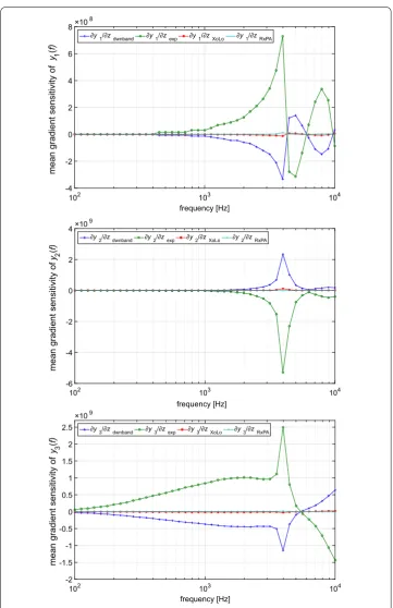
pseudo-Figure 7Mean gradient sensitivity analysis performed for the testbench model. Shown are the means of the coordinates of the gradient of the modulus of the cross-domain frequency response transfer functionsy1,y2
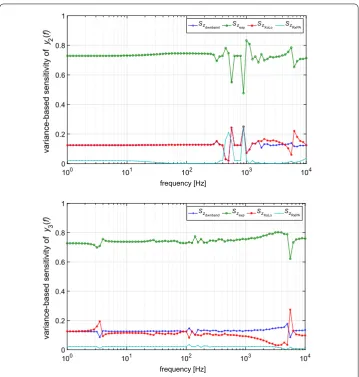
Figure 8Variance-based sensitivity performed for the testbench model. Due to the normalization, a value close to 1 means a large (‘dominant’) contribution to the variance
spectral method for the UQ analysis has been implemented in Python v.2.7.6 using the DAKOTA v.6.2 library [1]. For this purpose, first the set of random parameters p and weights w have been generated using Stroud 3 quadrature rule. Next, for each quadrature nodepk,k= 1, . . . ,K,K= 2J= 8, the deterministic simulation of the RFIC model has been run. Due to the application of the uniform distribution for modeling random variables, it holds thatwk= 1/8. Finally, a priori unknown coefficients of the truncated polynomial
chaos have been calculated using (9). The results for the variance-based and mean gradient sensitivity, analyzed in the first iteration of the optimization process, have been depicted on Figs.8and7, respectively.
Figure 9Result for stochastic optimization of an RFIC problem : mean and standard deviation of the modulus of the cross-domain frequency response transfer functionsy1,y2andy3[28]
6 Conclusion
Table 3 The mean values for the optimized configuration [28]
Rdb_rxpa Ldb_rxpa Rvia_exp Lvia_exp Rlb_xolo Llb_xolo Rlb_rxpa Llb_rxpa
Mean values 9.37 [m] 0.0187 [nH] 0.13 [m] 0.0138 [nH] 25.0 [m] 0.5 [nH] 0.36 [m] 7.22 [nH]
the computationally expansive simulation of the EMC, we have applied the equivalent lumped model developed by the NXP Semiconductor. It allows for conducting each sim-ulation within the realistic time of about several seconds. Furthermore, based on the re-sponse surface model by truncated PCE, it has been possible to provide both the variance-based and local sensitivity analysis of the cross-domain coupling. Thanks to this analysis we could identify the most influential input parameters in a very efficient way. This infor-mation can be further used for the physics-based design of an RFIC.
Another effective solution relies in incorporating the UQ into the regularized Gauss-Newton procedure in order to find automatically impedances z. This approach applied in our work allows to reduce the coupling effect ofy3(f) in the mean sense approximately by
27 [dB] across the considered range of frequency (Fig.9). Also the standard deviation of
y2(f) andy3(f) have been considerably reduced by 90% in average sense.
However, in our opinion, the application of the Pareto front method to solve a multi-objective problem can further improve the provided results for the RFIC interference problem due to competing objective functionsy2andy3. In such a case, the AWM might
not approximate properly the Pareto front. However, this issue is considered as a further direction of our research.
Acknowledgements
The authors are grateful to the financial support from the European Union in the FP7-ICT-2013-11 Programme.
Funding
This FP7 Collaborative Project nanoCOPS is supported by the European Union in the FP7-ICT-2013-11 Programme under Grant Agreement Number 619166 (Project nanoCOPS—nanoelectronic COupled Problems Solutions). For further details seehttp://www.fp7-nanocops.eu/.
List of abbreviations
nanoCOPS, Nanoelectronic COupled Problems Solutions; RF, Radio Frequency; RFIC, Radio Frequency Integrated Circuit; SCM, Stochastic Collocation Method; PCE, Polynomial Chaos Expansion; EMI, Electromagnetic Interference; RFCMOS, Radio-Frequency Complementary Metal-Oxide Semi-Conductor; CEM, Computational Electromagnetic; EMC, Electromagnetic Compatibility; IC, Integrated Circuit; ICs, Integrated Circuits; IP, Intellectual Property; UQ, Uncertainty Quantification; ADC, Analog-to-Digital Converter; RxPA, Receiver and Power Amplifier; XoLO, Crystal oscillator and Local Oscillator; IO, Input/Output; IOs, Input/Output systems; PCB, Printed Circuit Board; ECM, Equivalent Circuit Model; ADS, Advanced Design System; MoM, Methods of Moments; PDEs, Partial Differential Equations; MNA, Modified Nodal Analysis; DAEs, Differential-Algebraic Equations; DAC, Digital-to-Analog Converter; VCO, Voltage Controlled Oscillator; PC, Polynomial Chaos; DAKOTA, Design Analysis Kit for Optimization and Terascale Applications.
Availability of data and materials
The data that support the findings of this study are available from NXP, but restrictions apply to the availability of these data, which were used under license for the current study, and so are not publicly available.
Competing interests
The authors declare that they have no competing interests.
Authors’ contributions
All authors contributed to the writing of the final version of this paper. However, special merits go to RJ, JN and TB for sharing their experiences from industry, which yielded the development of the methodology for UQ modeling and optimizing of the real-life device; to RP for his work on the UQ; to PP, JtM and MG for their contribution to the robust optimization. All authors read and approved the final version of manuscript.
Author details
Endnote
a In Fig.6Digital
vdd=vdddig;Digitalgnd=gnddig,RxPAgnd=gndRxPA; not found in Fig.6:gndadc,XoLOgndare mentioned in Fig.2.
Publisher’s Note
Springer Nature remains neutral with regard to jurisdictional claims in published maps and institutional affiliations.
Received: 28 March 2018 Accepted: 12 November 2018 References
1. Dakota 6.3—algorithms for design exploration and simulation. Albuquerque, NM: Sandia National Laboratories; 2015. https://dakota.sandia.gov/.
2. Bruns HD, Schuster C, Singer H. Numerical electromagnetic field analysis for EMC problems. IEEE Trans Electromagn Compat. 2007;49(2):253–62.
3. Casper T, De Gersem H, Gotthans T, Schoenmaker W, Schöps S, Wieers A. Electrothermal simulation of bonding wire degradation under uncertain geometries. In: Proceedings of the 2016 design, automation & test in Europe conference & exhibition (DATE); 2016.
4. Chapter SC 47A: integrated circuits.http://www.iec.ch/emc/emc_prod/prod_main.htm.
5. Chua LO, Lin PM. Computer aided analysis of electronic circuits: algorithms & computational techniques. Englewood Cliffs: Prentice Hall; 1975.
6. Collin RE. Field theory of guided waves. New York: IEEE Press; 1990. 7. Conway J. A course in functional analysis. New York: Springer; 1997.
8. Di Bucchianico A, ter Maten J, Pulch R, Janssen R, Niehof J, Hanssen J, Kapora S. Robust and efficient uncertainty quantification and validation of RFIC isolation. Radioengineering. 2014;23:308–18.
9. Eaton JW, Bateman D, Hauberg S, Wehbring R. GNU Octave version 3.8.1 manual: a high-level interactive language for numerical computations. CreateSpace Independent Publishing Platform; 2015.
http://www.gnu.org/software/octave/doc/interpreter. 10. Eberly D. Derivative approximation by finite differences; 2008.
http://www.geometrictools.com/Documentation/FiniteDifferences.pdf(last modified: March 2).
11. Feldmann U, Günther M. CAD-based electric-circuit modeling in industry I: mathematical structure and index of network equations. Surv Math Ind. 1999;8:97–129.
12. Gharpurey R, Meyer RG. Modeling and analysis of substrate coupling in integrated circuits. IEEE J Solid-State Circuits. 1996;31(3):344–53.
13. Günther M, Feldmann U, ter Maten J. Modelling and discretization of circuit problems. In: Ciarlet PG, editor. Handbook of numerical analysis. Vol. 13. Amsterdam: Elsevier; 2005. p. 523–659.
14. Ilievski Z, Xu H, Verhoeven A, ter Maten EJW, Schilders WHA, Mattheij RMM. Adjoint transient sensitivity analysis in circuit simulation. In: Scientific computing in electrical engineering. Berlin: Springer; 2006. p. 183–9. (Mathematics in industry; vol. 11).
15. Kapora S, Hanssen M, Niehof J, Sandifort Q. Methodology for interference analysis during early design stages of high-performance mixed-signal ICs. In: Proceedings of the 2015 10th international workshop on the electromagnetic compatibility of integrated circuits (EMC Compo); 2015. p. 67–71.
16. Koch PN, Yang R-J, Gu L. Design for six sigma through robust optimization. Struct Multidiscip Optim. 2004;26:235–48. 17. Marler RT, Arora JS. Survey of multi-objective optimization methods for engineering. Struct Multidiscip Optim.
2004;26:369–95.
18. Momentum Keysight Technologies.http://www.keysight.com/en/.
19. Nakhla NM, Nakhla M, Achar R. A general approach for sensitivity analysis of distributed interconnects in the time domain. IEEE Trans Microw Theory Tech. 2011;59:46–55.
20. Niehof J, van Sinderen J. Preventing RFIC interference issues: a modeling methodology for floorplan development and verification of isolation- and grounding strategies. In: Proceedings of the 2011 15th IEEE workshop on signal propagation on interconnects (SPI); 2011. p. 11–4.
21. Nikolova NK, Bandler JW, Bakr MH. Adjoint techniques for sensitivity analysis in high-frequency structure CAD. IEEE Trans Microw Theory Tech. 2004;52:403–19.
22. Nikolova NK, Zhu J, Li D, Bakr MH, Bandler JW. Sensitivity analysis of network parameters with electromagnetic frequency-domain simulators. IEEE Trans Microw Theory Tech. 2006;54:670–81.
23. Pulch R, Putek P, De Gersem H, Gillon R. Identification of probabilistic input data for a glue-die-package problem. In: Quintela P, Barral P, Gómez D, Pena FJ, Rodríguez J, Salgado P, Vázquez-Mendéz ME, editors. Progress in industrial mathematics at ECMI 2016. Cham: Springer; 2017. (Mathematics in industry; vol. 26).
24. Pulch R, ter Maten EJW, Augustin F. Sensitivity analysis of linear dynamical systems in uncertainty quantification. Proc Appl Math Mech. 2013;13:507–8.
25. Pulch R, ter Maten EJW, Augustin F. Sensitivity analysis and model order reduction for random linear dynamical systems. Math Comput Simul. 2015;111:80–95.
26. Putek P. Mitigation of the cogging torque and loss minimization in a permanent magnet machine using shape and topology optimization. Eng Comput. 2016;33:831–54.
27. Putek P, Crevecoeur G, Slodiˇcka M, van Keer R, Van de Wiele B, Dupré L. Space mapping methodology for defect recognition in eddy current testing—type NDT. Compel. 2012;31(3):881–94.
28. Putek P, Janssen R, Niehof J, ter Maten EJW, Pulch R, Günther M. Robust optimization of an RFIC isolation problem under uncertainties. In: Scientific computing in electrical engineering. Berlin: Springer; 2018. p. 177–86. (Mathematics in industry; vol. 28).
30. Putek P, Meuris P, Günther M, ter Maten EJW, Pulch R, Wieers A, Schoenmaker W. Uncertainty quantification in electro-thermal coupled problems based on a power transistor device. IFAC-PapersOnLine. 2015;48:938–9. 31. Putek P, Meuris P, Pulch R, ter Maten EJW, Günther M, Schoenmaker W, Deleu F, Wieers A. Shape optimization of a
power MOS device under uncertainties. In: Proceedings of the 2016 design, automation & test in Europe conference & exhibition (DATE); 2016. p. 319–24.
32. Putek P, Meuris P, Pulch R, ter Maten EJW, Schoenmaker W, Günther M. Uncertainty quantification for robust topology optimization of power transistor devices. IEEE Trans Magn. 2016;52:1700104.
33. Putek P, Pulch R, Bartel A, ter Maten EJW, Günther M, Gawrylczyk KM. Shape and topology optimization of a permanent-magnet machine under uncertainties. J Math Ind. 2016;6:11.
34. Putek P, ter Maten EJW, Günther M, Sykulski JK. Variance-based robust optimization of a permanent magnet synchronous machine. IEEE Trans Magn. 2017;54:8102504.
35. Putek P. Nonlinear magnetoquasistatic interface problem in a PM machine with stochastic PDE constraint. Eng Optim. 2018. Accepted for publication.
36. Schwarz DE, Tischendorf C. Structural analysis of electric circuits and consequences for MNA. Int J Theor Appl. 2000;28:131–62.
37. Stanisavljevic´c M, Schmid A, Leblebici Y. Reliability of nanoscale sircuits and systems: methodologies and circuit architectures. New York: Springer; 2011.
38. Sudret B. Global sensitivity analysis using polynomial chaos expansion. Reliab Eng Syst Saf. 2008;93(7):964–79. 39. Sun H, Zhu B, Sun L, Li H, Yang L. EMC computer modelling and simulation of integrated circuited in QFN package.
Prog Electromagn Res M. 2013;33:263–75.
40. Taguchi G. Taguchi techniques for quality engineering. New York: Quality Resources; 1987. 41. Tellegen BDH. A general network theorem, with applications. Philips Res Rep. 1952;7:259–69.
42. Tiesler H, Kirby RM, Xiu D, Preusser T. Stochastic collocation for optimal control problems with stochastic PDE constraints. SIAM J Numer Anal. 2012;50:2659–82.
43. Xiu D. Efficient collocational approach for parametric uncertainty analysis. Commun Comput Phys. 2007;2:293–309. 44. Xiu D. Numerical methods for stochastic computations—a spectral method approach. Princeton: Princeton
University Press; 2010.
45. Xiu D, Hesthaven J. High-order collocation methods for differential equations with random inputs. SIAM J Sci Comput. 2005;27(3):1118–39.
46. Xiu D, Karniadakis GE. Modeling uncertainty in steady state diffusion problems via generalized polynomial chaos. Comput Methods Appl Mech Eng. 2002;191:4927–48.
47. Yao W, Chen X, Luo W, van Tooren M, Guo J. Review of uncertainty-based multidisciplinary design optimization methods for aerospace vehicles. Prog Aerosp Sci. 2011;47:450–79.
48. Yildiz ÖF, Preibisch JB, Niehof J, Schuster C. Sensitivity analysis and empirical optimization of cross-domain coupling on RFICs using polynomial chaos expansion. In: 2017 IEEE international symposium on electromagnetic

![Figure 4 Coupling between different ground domains of the packaged IC. Measurements (solid) vs.simulations by isolation methodology (dashed) [15]](https://thumb-us.123doks.com/thumbv2/123dok_us/9609413.1943220/7.595.118.478.538.699/figure-coupling-dierent-packaged-measurements-simulations-isolation-methodology.webp)

![Figure 9 Result for stochastic optimization of an RFIC problem : mean and standard deviation of the modulusof the cross-domain frequency response transfer functions y1, y2 and y3 [28]](https://thumb-us.123doks.com/thumbv2/123dok_us/9609413.1943220/16.595.119.476.76.633/stochastic-optimization-deviation-modulusof-frequency-response-transfer-functions.webp)
![Table 3 The mean values for the optimized configuration [28]](https://thumb-us.123doks.com/thumbv2/123dok_us/9609413.1943220/17.595.115.478.96.125/table-mean-values-optimized-conguration.webp)
