Transmit / Received Beamforming for Frequency Diverse Array
with Symmetrical frequency offsets
Shaddrack Yaw Nusenu*
1University of Electronic Science and Technology of China, School of Communication and Information Engineering,
China.
1Koforidua Technical University, Electrical / Electronic Department, Faculty of Engineering, Ghana.
A R T I C L E I N F O A B S T R A C T
Article history:
Received: 17 February, 2017 Accepted: 07 March, 2017 Online: 15 March, 2017
Frequencydiversearray(FDA)employsasmallfrequencyincrementacross itsarrayelementstoproviderange,angleand timedependentbeampattern. In most radar systems, FDA with linear frequency offsets have been employed. But, its transmit beampattern is coupled in range and angle dimensions,whichmaydegradetheoutput signal-to-interference-plus-noise ratioperformance.NotethatnonlinearoffsetisalsobeneficialinFDAradar. Inthispaper,symmetricalfrequencyoffsetsbasedFDAisinvestigatedwhich removes the inherent periodicity of FDA beampattern to achieve a single maximainthetargetarea.Indoingso,thesignalinformationatthereceiver is improved significantly. Transmit/received beampatterns, signal-to-interference-plus-noise ratio (SINR) and detection probability of the proposedmethod are compared with the conventional FDA. Computer simulationsareusedtoverifytheeffectivenessoftheproposedmethod. Keywords :
Frequency diverse array Linear frequency increment Symmetrical frequency offset Transmit and received beam-forming
1
Introduction
Frequency diverse array (FDA) utilizing a small frequency increment across each antenna elements was proposed by [1], to steer the beam electronically in angle and range di-mensions. The FDA concept has range dependent beam-forming capability. It was observed that frequency incre-ment makes the array beampattern changes as a function of the range, angle and time [1, 2, 3]. In [4], FDA applications for various modes of operations in radar systems has been presented. The periodicity of beam pattern in time, range and angle was investigated in [5]. In [6], a linear FDA was proposed to address the range ambiguous clutters and im-proves the detection ability in a relatively slow moving tar-gets. The radiation capabilities of FDA was presented in [7] to show its beam scanning features. Also it was proven that the scanning speed was related to frequency offset em-ployed between two neighboring antenna elements. In [8], the range and angle coupled beamforming with frequency diverse chirp signals was presented. In addition, [9] inves-tigated FDA range-angle dependent beamforming to sup-press interferences at different ranges and directions.
FDA has alot of promising application [10] which has sparked many interesting investigations in finding a suit-able frequency offset to provide range-angle dependent. It is important to mention that frequency offset across the FDA elements plays essential role in improving the over-all performance of an FDA radar, especiover-ally in controlling range-angle dependency and spatial distribution of gener-ated beam pattern [11, 12]. Hence, researchers have shown great interest to investigate frequency offset between the ad-jacent elements of FDA to improve it performance. Since FDA offers a range-angle-dependent beampattern, it is of great significance as this provides a potential for range-angle localization of targets, however, the beampattern of the conventional FDA is coupled in range-angle dimen-sion. In this regards, a nonuniform linear array was pro-posed in [13] to decouple the FDA transmit beampattern, however, the carrier frequency and/or frequency increments cannot be altered in real-time because it requires relocating the elements mechanically. In [14] and [15], logarithmi-cally increasing frequency offsets and time-dependent fre-quency offsets, respectively are reported to decouple the
*Shaddrack Yaw Nusenu, UESTC-China and Koforidua Technical
University Ghana, Email: nusenu2012gh@yahoo.com
www.astesj.com 1
X
0
f f0 f f0 2 f
0
r
1
r r2 rM 1
0 (M 1)
f f
d
X
0
f f0 f f0 222 f
0
r
1
r r2 rM 1111
0 (M 1)
f (((((M 1)(M 1))))) fff d
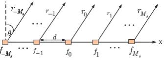
Figure 1: Illustration of Conventional FDA with linear frequency offsets.
range-angle beampattern. However, these methods resulted in poor beamforming performance in the range dimension. Note that the best decoupling way is to form a dot-shaped beampattern rather than S-shaped beampattern.
In this paper, transmit/received beamforming FDA radar with symmetrical frequency offset to decouple range and angle beampattern in order to produce a single maxima is investigated. The idea is to use the symmetrical fre-quency offset to provide extra degree of freedom in terms of producing single maxima for a particular target of in-terest in a given region. Due to single maxima the re-ceived signal at the receiver array will be better than the signal for the conventional FDA. Furthermore, the pro-posed transmit/received beamforming are evaluated by the signal-to-interference-plus-noise ratio (SINR) and detec-tion probability. Results shows the superiority of the pro-posed method.
The remaining sections are organized as follows : Sec-tion II presents the signal model of the convenSec-tional FDA, followed by the proposed symmetrical frequency offset FDA radar. Section III derives the SINR and detection prob-ability. Section IV presents results and discussions and con-cluding summaries are drawn in Section V.
2
Background
2.1
Conventional FDA Range-Angle
Depen-dent Transmit Beampattern
Figure 1 shows the conventional FDA antenna array struc-ture.
The narrow-band monochromatic signal radiated from each element is identical but with a frequency increment ∆f. The radiated frequency of themth element can be ex-pressed as
fm=f0+m∆f , m= 0,1, . . . , M−1 (1)
wheref0 is the carrier frequency and M is the number of array elements. Then, the signal transmitted by themth el-ement can be represented by
sm(t) = exp (−j2πfmt). (2)
The signal arriving at a far-field point(r, θ)can be ex-pressed as
sm t−
rm
c0
!
= exp
(
−j2πfm t−rm
c0
!)
(3)
wherec0is the speed of light andrm≈r−mdsinθ, withd being the element spacing, is the target slant range for the
mth element. If uniform weights (all ones) are applied, the array factor can be approximately derived as [16]
AF(t;r, θ) = M−1
X
m=0 exp
(
−j2πfm t−rm
c0
!)
≈e−jΦ0sin
h
Mπ∆f t−∆f r c0 +
df0sinθ
c0 +
∆f dsinθ c0
i
sinhπ∆f t−∆f r c0 +
df0sinθ
c0 +
∆f dsinθ c0
i
(4)
where Φ0 = 2πf0(t−r/c0)−π(M−1)∆f r/c0+π(M− 1)f0dsinθ/c0+π(M−1)∆f dsinθ/c0.
Equation (4) implies that FDA has range, angle and time dependent transmit beampattern. However, the beampattern is coupled in the range and angle dimensions and conse-quently it will have multiple maximums. To avoid the de-pendence of range gain on the angle, the FDA parameters should be properly designed.
2.2
Proposed Symmetrical Frequency offset
FDA for Transmit/Received
Beamform-ing
In this paper, the symmetrical frequency offsets is proposed to decouple range and angle beampattern in order to local-ize a target in a given region. In designing symmetrical frequency offset, the central element is chosen as the sym-metric point depicted in Figure 2.
In this paper, odd number of elements are assumed, namely, M = 2Ms−1. The frequency offset for thekth element can be expressed as
∆fk=|k|∆f , k=−Ms+ 1, . . . ,0,1, . . . , Ms−1. (5)
Note that in order to show distinct representations, a new element indexk∈[−Ms+ 1,· · ·,0,· · ·, Ms−1]instead ofm defined in (1) is adopted. Reformulate (4) as
AF(θ, r, t) = Ms
X
k=−Ms
1 rk
exp
(
−j2π
"
(f0+|k|∆f) t− rk
c0
!#)
≈ 0
X
k=−Ms
1 rexp
(
−j2π
"
(f0−k∆f) t−rk c0
!#)
+ Ms
X
k=1 1 rexp
(
−j2π
"
(f0+k∆f) t−rk c0
!#)
(6)
Similarly,rk≈r−kdsinθis used, whererdenotes here as the reference range to the central element. Equation (6) can be rewritten as a general vector formulation:
X s M r • d
L
L
L
1 f 1 r 0 f 1 f • 1 r •L
s M r s M f s M f 0 r X s M r • dL
L
L
1 f 1 r 0 f 1 f • 1 r •L
s M r ssss rr s M f ssss ff s M f 0 rFigure 2: Illustration of proposed FDA with symmetrical frequency offsets.
whereHis the conjugate transpose operator,wis theM×1 weighting vector, and transmit steering vectora(θ, r, t)is
a(θ, r, t) = 1 r
h
e−jΦ−Ms
,· · ·,1,· · ·, e−jΦk,· · ·, e−jΦMsiT (8)
withT being the transpose operator and
Φk= 2π(f0+|k|∆f) t− rk
c0
!
. (9)
Thewcan be optimally designed to synthesize the desired transmit beampattern.
3
Transmit / Received Beamforming
for Symmetrical frequency offset
FDA
In this section transmit and received beamforming for pro-posed method is presented. The transmit beamforming can be expressed as
BT(θ, r) =
w
Ha(θ, r)
2
wHa(θd, rd)
2 (10)
The normalized received beampattern can be written as
Br(θ, r) =
wr
Hv(θ, r)
2
wrHv(θd, rd)
2 (11)
where v(θ, r) =wHa(θ, r)b(θ) denotes the virtual steering vectorv(θ, r)andb(θ)being the receive steering vector due to the propagation delays from a source to the receive elements.
4
Performance Analysis
4.1
SINR
The performance analysis of the proposed method are eval-uated by signal-to-interference-plus-noise ratio (SINR) and probability of detection. First of all SINR can be expressed as
SIN R=σ 2 d
wr
Hv(θ d, rd)
2
wrHQi+nwr
(12)
where σd2 is the variance of the target reflection coeffi-cient andQi+n denotes the interference-plus-noise covari-ance matrix which is given as
Qi+n
∆ =
F
X
i=1
σi2v(θi, ri)vH(θi, ri) +σn2I (13)
whereσi2 is the variance of theith interference reflection coefficient,Fis the number of interferences andσn2I is the covariance matrix withIbeing an identity matrix. Plugging in (13) andwr =v(θd, rd)into (12) for any radar system, will yields SINR for that radar system.
4.2
Probability of Detection (Pd)
In this section, the probability of detection (Pd) is employed to evaluate the performance of a radar system. For the pro-posed method, the hypothesis problem can be written as
H0: x(t)=n(t)
H1: x(t)=h(t)+n(t) (14)
The noise process is assumed to be Gaussian and inde-pendent and identically distributed (i.i.d). The probability density function (PDF) can be expressed as
p(x(t) ;H0) =e
−kx(t)k2
σn2
(15)
p(x(t) ;H1) =e
−kx(t)k2
σn2
·e
−kh(t)+n(t)k2
2σn2
(16)
The likelihood ratio test can be given as
γ=p(x(t) ;H1) p(x(t) ;H0)
H1 > < H0
ξ (17)
The probability of detectionpdand probability of false alarmpf a, respectively, is expressed as in [17]
pd=p
γ > ξ H1
= 1−S ψ2(2)
σn2S
−1
ψ2(2)
1−pf a
M2N+σ2 n (18)
pf a=p
γ > ξ H0
= 1−S ψ2(2)
2ξ σn2
!
(19)
whereS(·)denotes the cumulative distributive function,ψ2 (2)
being the chi-square distribution.
5
Results and Discussions
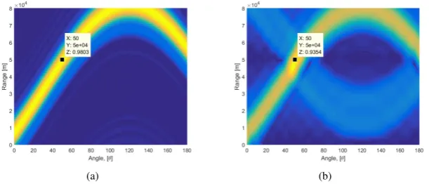
In the simulations, the carrier frequencyf0= 10GHz, fre-quency offset∆f = 3KHz. Both the transmit and receive arrays M and N, respectively, have 8 antenna elements spaced by half wavelengthd=2cf
0. The target is assumed
to be located at(θd, rd) = (50
◦
(a) (b)
Figure 3: Comparisons of normalised transmit beampattern when∆f = 3KHzis adopted: (a) Conventional FDA, (b) Proposed symmetrical FDA.
(a) (b)
Figure 4: Comparisons of transmit beampattern when the target is present at(θd, rd) = (50◦,50km): (a) Conventional FDA, (b) Proposed symmetrical FDA.
5.1
Transmit Beampattern
First, normalised transmit beampattern for FDA and the proposed symmetrical FDA is presented to show the effec-tiveness of symmetrical FDA. Note that the two arrays are steered to instantaneous angleθ= 0◦and the beam direc-tion ranges are also normalised to zero-range.
Figure 3(a) illustrates the conventional FDA beampat-tern which is coupled in the range-angle dimension. In contrast, Figure 3(b) shows the proposed symmetrical FDA which has decoupled range-angle beampattern. And this is beneficial for targets localization.
As shown in Figure 4(a), the conventional FDA beam-pattern shows the problem of periodic maxima. These max-ima are undesirable for proper target localization. On the other hand, Figure 4(b) shows the proposed method beam-pattern which produce exactly one maxima at target loca-tion and no other maxima is seen in the entire region of observation.
5.2
Received Beampattern
In Figure 5(a) and 5(b) both radars produce maxima at the intended range-angle pair, but the conventional FDA has more serious ambiguity problem shown by the arrow in Fig-ure 5(a). It is important to mention that because the con-ventional FDA has larger total frequency offset, it achieved higher range resolution than the proposed method. In the case of the proposed method shown in Figure 5(b), the
tar-get is better localized than the conventional FDA. It can be noticed that there is no spread of beampattern in both range and angle dimensions.
Finally, SINR and probability detection performance of the proposed method and the conventional FDA have been plotted. It can be observed that in Figure 6, the SINR of proposed symmetrical FDA is better than the conventional FDA. Thus proposed method has better robustness against the interferences. Figure 7 shows the detection probability versus SNR for the proposed method and the conventional FDA radar. Proposed method exhibits better detection per-formance compared to the conventional FDA radars. Im-provement in performance in terms of SINR and detection probability can be attributed to single maxima due to sym-metrical frequency offset employed across the transmit an-tenna array.
6
CONCLUSION
(a) (b)
Figure 5: Comparisons of received beampattern when the target is present at(θd, rd) = (50◦,50km): (a) Conventional FDA, (b) Proposed symmetrical FDA.
SNR [dB]
-30 -20 -10 0 10 20 30
Output SINR [dB]
-30 -20 -10 0 10 20 30 40 50 60
Symmetrical FDA radar FDA radar
Figure 6: SINR versus SNR performance.
SNR [dB]
0 2 4 6 8 10 12 14 16 18 20
Probability of Detection [Pd]
0 0.1 0.2 0.3 0.4 0.5 0.6 0.7 0.8 0.9 1
Symmetrical FDA radar FDA radar
the proposed method received beampattern show a reason-able improvement compared to the conventional FDA.
Conflict of Interest The author declare no conflict of in-terest.
Acknowledgment The author would like to thank Re-spected Professor Wen-Qin Wang (Senior Member - IEEE) of UESTC for his great contributions, support and encour-agement.
References
[1] Antonik, P., Wicks, M.C., Griffiths, H.D., et al. “Fre-quency diverse array radars,” Proc. of the IEEE Radar Conf., Verona, NY, April 2006, pp. 215-217
[2] Wicks, M.C., Antonik, P. “Frequency diverse array with independent modulation of frequency, amplitude, and phase,” U.S.A Patent 7,319,427, 15 January 2008
[3] Wicks, M.C., Antonik, P. “Method and apparatus for a frequency diverse array,” U.S.A Patent 7.511,665B2, 31 March 2009
[4] Antonik, P., M. C. Wicks, H. D. Griffiths, and C. J. Baker. “Multimission multi-mode waveform diver-sity,” Proc. IEEE Radar Conf. Dig., 580582, Verona, NY, USA, Apr. 2006, pp. 24-27.
[5] Secmen M., Demir S., Hizal A., Eker T. “Frequency diverse array antenna with periodic time modulated pattern in range and angle,” IEEE Conference on Radar, 2007
[6] Wen-Qin Wang. “Range-Angle Dependent Transmit Beampattern Synthesis for Linear Frequency Diverse Arrays,” IEEE Transactions Signal Processing. 61 (8), 2013, pp. 4073–4081.
[7] Huang S., Tong K. F., Baker C. J. “Frequency diverse array with beam scanning feature,” Proc. IEEE Anten-nas Propag. Conf., USA, July 2008.
[8] Higgins T. and S. Blunt. “Analysis of range-angle coupled beamforming with frequency diverse chirps,”
Proceedings of the4th International Waveform Diver-sity and Design Conference, Orlando, FL, Feb. 2009, pp. 140-144.
[9] Huaizong Shao, Jingchi Li, Hui Chen, and Wen-Qin Wang. “Adaptive Frequency Offset Selection in FrequencyDiverse Array Radar,” IEEE Antennas and Wireless Propagation Letters, vol. 13, 2014.
[10] W.-Q. Wang. “Overview of frequency diverse array in radar and navigation applications,” IET Radar, Sonar and Navigation, doi: 10.1049/ietrsn.2015.0464, vol. 10, 2016.
[11] Zhuang, L. and X. Z. Liu. “Precisely beam steering for frequency diverse arrays based on frequency offset selection,” Proc. Int. Radar Conf., pp. 1-4, 2009.
[12] Chen, Y.-G., Y.-T. Li, Y.-H. Wu, and H. Chen. “Re-search on the linear frequency diverse array perfor-mance,” Proc. IEEE 10th Int. Conf. on Signal Process-ing, 23242327, BeijProcess-ing, Oct. pp. 24-28, 2010.
[13] W.-Q. Wang, H. C. So, and H. Z. Shao. “Nonuni-form frequency diverse array for range-angle imaging of targets,” IEEE Sensors Journal, vol. 14, no. 8, pp. 2469-2476, August 2014.
[14] W. Khan, I. M. Qureshi, and S. Saeed. “Frequency di-verse array radar with logarithmically increasing fre-quency offset,” IEEE Antennas and Wireless Propaga-tion Letters, vol. 14, 2015.
[15] W. Khan and I. M. Qureshi. “Frequency diverse ar-ray radar with timedependent frequency offset,” IEEE Antennas and Wireless Propagation Letters, vol. 13, 2014.
[16] Sammartino, P.F., Baker, C.J., Griffiths, H.D. “Fre-quency diverse MIMO techniques for radar,” IEEE Trans. Aerosp. Electron. Syst., 2013, 49, (1), pp. 201-222.