Evaluation of the Effect of Lime-Stabilized
Subgrade on the Performance
of an Experimental Road Pavement
József Péterfalvi, Péter Primusz, Gergely Markó, Balázs Kisfaludi, Miklós Kosztka
Abstract
Forest roads should be constructed to provide economic wood transport routes while causing minimal environmental impact. Therefore, the extended use of local materials (soil, stone) is essential. As cohesive soils cannot be drained by gravity and saturated cohesive soils have low bearing capacity, their use as a building material raises problems. This issue can be solved by lime stabilizing the soil. An experimental road was constructed to evaluate the effect of lime stabilized cohesive soil on the pavements built on top of it. Nine pavement versions were built on three different thickness (15, 25 and 35 cm) of lime stabilized soil. A traditional pavement without lime stabilization was also built for comparison. The bearing capacity of the stabilized layers and the finished pavements were calculated. The long term performance of the pavements was tested by measuring the effect of artificial traffic on their bearing capacity. Results showed that the bearing capacity modulus of the lime stabilization was around 500 MPa. 25–35 cm of lime stabilization under the pavements was necessary for good long term performance. 35 cm thickness of the stabilized local soil was enough to withstand the applied traffic without serious damage. Therefore, lime treated cohesive soil can be recommended as a subgrade layer in for-estry conditions.
Keywords: forest opening up, lime-stabilization, road test, bearing capacity
1. Introduction
Stabilized local soil can usually be applied as the subgrade course of a road pavement. Cohesive soils can be stabilized by lime. Between 1960 and 1970 ap
-proximately 53 km of forest roads were built on lime stabilized subgrade in South-Western Hungary. The economic and technological conditions of the follow
-ing period were not conductive to the spread-ing of the lime stabilization method. As a result the stabilization experiments were neglected. Nowadays, the tighten
-ing economic situation, the increas-ing ecological re
-quirements and the appearance of modern rotary mix
-ers and binding material feed-ers have led to the rediscovery of stabilizing methods. For reasons of en
-vironmental protection, the use of local soil, advanta
-geous as input of external material (e.g. crushed stone) onto the area, can be reduced. Lime as an adhesive is present in nature and the quantity of application is not significant.
Current public road regulations in Hungary do
not consider stabilized local soil as a bearing layer in
the pavement design process. Stabilizations are con
-sidered only as soil improvement methods. It was hypothesized that stabilized local soil can act as a standalone pavement type for low volume roads. To evaluate the relevance of this hypothesis an experi
-mental road was built. The first aim of the experimen
-tal road was to determine the bearing capacity of lime stabilized layers that can be taken into account in the design process of forest road pavements. The study of traffic resistance of pavements built on lime stabi
-lized local soil was the second aim of the experimen
-tal road. By constructing one of the test sections with only lime stabilized soil, we have the opportunity to examine the possibilities of this method in the im
-ume of crushed stone could be reduced, not only ma
-terial costs would be lower, but transportation costs could be decreased as well.
1.1 Soil treatment with lime
Lime has been used for a long time to improve me
-chanical properties of cohesive soils. By absorbing water, lime transforms to lime hydrate, while produc
-ing heat. If lime hydrate is mixed into the soil, the Ca++
ions bind to the surface of clay particles and they re
-move water and other ions from there. As a result, the plasticity index of the soil decreases significantly, and the soil becomes granular (Szendefy 2013). If enough lime is added, the pH increases so much that clay par
-ticles start to disintegrate. The resulting aluminium and silicon ions react with the calcium ions and to
-gether they form hydrates. These hydrates form a net
-work that further increases the bearing capacity of the soil (NLA 2004). According to experiences, moist co
-hesive soils can be dried by the addition of 1–3 mass percentage of lime. In addition to the drying effect, the result of a 3–5 mass percentage lime treatment is sig
-nificant increase in the bearing capacity, the shear strength and the optimum moisture content of the soil. The quantity of the lime is determined by the proper
-ties of the soil to be treated and the lime itself. The current practice of the quantity determination is to conduct laboratory tests (Tárczy 2007).
Lime stabilized soils can be produced on-site or at a mixing plant. In case of on-site mixing, lime can be mixed right into the soil or soil can be excavated and mixed with lime. The first step of on-site mixing is to spread dry quicklime or dry hydrated lime on the sur
-face of the soil to be treated in the predetermined amount. Application of quicklime is more favorable due to its higher lime content and faster reactions. The produced heat is also higher and, therefore, the con
-struction period may be extended. The downside of quicklime is that it requires more water and it is more difficult to mix with soils than hydrated lime.
Lime application can be done by hand or by ma
-chines. Mechanical spreading is more efficient. The amount of applied lime can be regulated by the feeder opening and the speed of the feeder. Mixing can be done by a grader or by rotary mixing. If its capacity is appropriate, the use of a rotary mixer is more favorable since it achieves better mixing quality in less time. Wa
-ter has to be added to the soil as needed during the mixing procedure. This may be done by water sprayer trucks or a rotary mixer with water supply capability. Mixing can generally be carried out in one stage. In case of soils with high clay content, it is appropriate to mix in two stages. 24–72 hours should pass between the two
mixing stages. After the first stage, the subgrade has to be sealed by light rolling. In order to achieve appropri
-ate bearing capacity, the stabilized soil needs compac
-tion. Compaction can be performed several ways. The common practice is to use a sheep foot roller or a vibrat
-ing steel wheel roller followed by a rubber tired roller. Compaction should be commenced shortly after mixing though a delay of four days is usually acceptable in humid conditions (Little 1995, Tárczy 2007).
1.2 Full scale road tests
In order to determine the lime quantity and quality suitable for a given soil, laboratory tests should be con
-ducted. Based on these tests, different soil and lime types can be compared. Though the best way to study the behavior of various pavements and bases on differ
-ent soils is to study them on real life roads. Since the deterioration of roads is a slow process, full scale ac
-celerated pavement testing has gained ground. For these tests, different pavement types are actually built and tests are conducted on them. The aim of the tests is usually to determine the reaction of different pavement types to a given amount of traffic load (Metcalf 1996).
The most widely known tests of this kind were the AASHO (American Association of State Highway Of
-ficials) Road Tests. These experiments were carried out in the USA between 1956 and 1962. The aim of these tests was to develop a methodology for highway pave
-ment design. For this reason, 470 types of pave-ments were built on weak soil. Pavements consisted of sandy gravel, crushed stone and asphalt concrete courses. The experimental road section was loaded with artifi
-cial traffic for two years. The condition of the pave
-ments was evaluated regularly. Evaluation was carried out by visual deterioration assessment and the mea
-surement of longitudinal road profile and central de
-flection. The most important result of the experiment was the determination of the connection between de
-sign parameters of pavements (equivalent thickness), axle load and configuration as well as the number of loads. The resulting functions proved to be useful in case of different types of soils and pavements (High
-way Research Board 1961).
The experimental road »SERUL« (Laval University Road Experimental Site) was built in Canada specifi
-cally to study forest road pavements in cold condi
-tions. Several pavements were built on the local soil. The study of the effect of different soil types is made possible by a three meters deep concrete trough the experiments on this site focused on the effect of thaw
built with lime applied in 3% and 5%, respectively. Central deflection was measured and visual deteriora
-tion assessment was carried out before and after the passing of real but known amount of traffic. Central deflection was changed from 2.44 mm to 0.77 mm in 4 months after construction (Behak 2011).
In Hungary an experimental road was built to study pavements typical for agricultural roads. 72 types of pavements were built on sand. Pavements consisted of asphalt and cement concrete surfacing, mechanical, cement and blast furnace slag stabiliza
-tions and/or crushed stone base courses. The pave
-ments were loaded with a total of 11 500 ESAL (Equiv
-alent Standard Axle Load). After evaluating the initial state of the pavements, the effect of five loading peri
-ods was measured. Meteorological data (daily min. and max. temperature, precipitation, soil tempera
-ture), performance (central deflection, deflection bowl) and traffic ability (longitudinal profile, rutting, crack
-ing, potholing and other surface failures) properties were determined. Based on these measurements, it was concluded that the 11 500 ESAL resulted in com
-plete failure only on those sections where construction deficiency occurred. Clear decrease in the bearing ca
-pacity was evincible by central deflection measure
-ments only after the last loading period. It was proven that the AASHO design formulas can be used in case of low volume roads, though they lead to slight overdesign. It was also concluded that the various sta
-bilization methods are suitable for agricultural and forest roads (Kosztka 1989).
2. Materials and Methods
A test road was built in 2006 to examine the behav
-ior of pavements built on lime stabilized local cohesive soil. Experiments were conducted to determine the bearing capacity of the lime stabilized layers. Artificial traffic loaded the road between 2007 and 2008 and bearing capacity was monitored to evaluate the per
-formance of the road. Since then, real life forestry traf
-fic has been loading the road and control measure
-ments are going to be done to evaluate the long term performance of the pavements.
2.1 Test site
The 580 m long experimental road is located at the Forestry of Bánokszentgyörgy in Zala County, which belongs to the »Zalaerdő Forestry Company«.
The subgrade of the experimental road was con
-structed using the medium clay soil in place. The most important soil physical properties are as follows:
Þ liquid limit, 44.6%; Þ plastic limit, 22.4%; Þ plasticity index, 22.2%; Þ flow index, 18.4%;
Þ maximum dry density, 1.82 g/cm3;
Þ optimum water-content for compaction, 15%. Precipitation conditions were analyzed using the data of the meteorological station of Bánokszent- györgy. There were 94 precipitation days; for forest road building it means only a low number of days for constructing the subgrade. The situation is especially disadvantageous as there is a significant quantity of rainfall (694 mm/year), which slows and complicates drying. This problem is increasing with clay subgrade that cannot be desiccated by gravity. Saturated sub
-grades permanently lose their bearing capacity and, therefore, they cannot support pavement courses. Among temperature conditions in the tested area, frost and thaw and their periodic alternation are of essential importance for road construction works. Frequent thaw frost effect can damage the pavement and thus can open a way to water into the pavement. Frost-thaw conditions can be characterized by these data:
Þ winter temperature, +3,7 °C; Þ January temperature, –0,4 °C; Þ number of frost days, 100–110 days.
2.2 Designed pavements
Different pavement versions were designed with about the same design bearing capacity. We used the AASHO Pavement Thickness Design Guide for it. This equivalent thickness was 30 ecm. Road sections with the same lime stabilization layer thicknesses were placed next to each other. The 15, 25 and 35 cm lime stabiliza
-tion layer was built using local soil in the first 360 me
-ters. Nine different pavements were built with asphalt concrete and crushed stone surfaces in different thick
-ness, each 40 m in length. Three different pavement courses were designed on the lime stabilization layer:
Þ well graded crushed dolomite course; Þ hot asphalt base course;
Þ Finnish asphalt course.
The most important dimensions of the cross-sec
-tion can be seen in Fig. 1. A tradi-tional pavement, with
-out lime stabilization, was built in the last 220 m as a control section. The control section was composed of sandy gravel and crushed stone layers built on the subgrade. To better understand the bearing capacity of the lime stabilization layer, the 5th pavement version was built with just 35 cm lime stabilization layer and with 2 cm of fine crushed stone. Fig. 2 shows the con
-structed pavements.
2.3 Lime stabilization bearing layer construction Constructing the lime stabilization layer was done as follows:
Þ pumping powdered quicklime into the binding material feeder;
Þ bringing the binding material feeder to the start
-ing point of construction;
Þ calibrating the binding material feeder; Þ checking the binding material feeder; Þ spreading the binding material; Þ mixing with a soil milling machine; Þ compacting with the vibration roller.
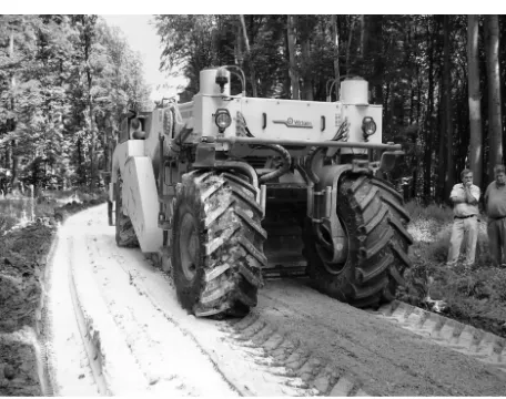
The binding material feeder spread the powdered quicklime on the whole surface of the subgrade in two passes. The spreading did not overlap; therefore, the spreading was in accordance with the plan. The soil milling machine performed the mixing in two courses with overlapping (Fig. 3). During the mixing, the ma
-chine set the thickness of the milling automatically.
The production line finished the lime stabilization with three different thicknesses and a width of 3.50 m in three hours.
2.4 Mechanical model of pavements
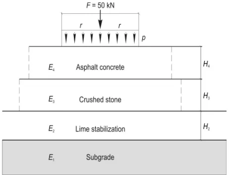
The layers stabilized with lime, and the mechanical parameters of granular layers without binding material within the multi layered pavements, can be represented within the elastic pavement structure model shown in Fig. 4. At the bottom, the model of the completed sub
-grade corresponds to the calculation of single layer sys
-tems as elastic, homogeneous infinite half space; that is, our topic will be a mass of unlayered soil, bounded with
Fig. 2 Pavement versions
horizontal plane, its dimensions are infinite horizon
-tally and in depth. There are layers of H2 thickness sta
-bilized with lime over the subgrade along the experi
-mental road sections; over them, there are granular (i.e. macadam) base layers of H3 thickness without bonding. Over all these, there are asphalt concrete layers of H4 thickness altogether. The layers are described by the E1, E2, E3, E4 moduli and the μ1, μ2, μ3, μ4 Poisson’s ratio num -bers (Huang 2003). The load is a ca. 2r =30 cm diameter circle shaped, steady load coming from a 50 kN weight, which nearly equals the tire pressure of big trucks p=0.7 MPa. More details about analytical sizing of elastic pavements can be read in the work of Bocz et al. (2009).
2.4.1 Correspondences of infinite homogeneous half space
In the applied model, the ground/subgrade is load
-ed with a p weight acting on a 2r=30 cm diameter rigid/flexible plate. The estimated calculation of shape changes caused by weight, regarding the elastic ho
-mogeneous half space, was worked out by Boussinesq in 1885. The deflection formula is the following (Yo
-der and Witczak 1975):
(
1 2)
pE c r
d
m
= × − × (1)
Where:
E elastic modulus of half space material, MPa; c Boussinesq plate factor (c=p/2 stiff and c=2,0 elas
-tic);
r radius of applied plate, mm; p greatest pressure applied, MPa; d vertical excursion under the plate, mm; μ Poisson ratio (–).
In the formula above, μ stands for the Poisson ratio, the well known material parameter in elasticity stud
-ies. The value of this may vary between 0≤μ≤0.5. If the soil is considered as incompressible liquid (cohesive soil (clay)), it can be μ=0.5. In this way, the subgrade can be calculated as homogeneous elastic half space. 2.4.2 Solution for the two layer system
The exact solution for the two layer system from mathematical mechanical point of view was given by Burmister in 1945. Later, he generalized his method
for n layers, between 1954 and 1956. He also presented a diagram (Fig. 5) for the solution of the two layer system – to prevent difficult calculations. To calculate the centre bending, he applied the formula used for single layer systems (Burmister 1945):
(
2)
1
2 1 p r
d F
E
m ×
= × − × (2)
In the formula, the modulus of the lower layer (the half space) is taken into account, which is then multi
-plied with an F deflection factor, defined on the basis of the known h/r and E2/E1 rates. The deflection factor equals the fraction,
1 e
E F
E
= (3)
Where:
Ee equivalent surface modulus (Nemesdy 1985).
It is important that the surface modulus is not a layer modulus, but an average parameter typical of all
Fig. 4 Model of flexible pavements
the layers together coming from the measurements done on the surface of the multilayer systems (Papa
-giannakis and Masad 2008).
2.4.3 Defining the modulus of granular layers The modulus of the layers consisting of round grains without bonding material depends on the mod
-ulus of the layer below them. One of the oldest solu
-tions is applied in the Shell sizing manual (Claussen et al. 1977):
0,45 2 1 0.2 2
E =E × ×H (4)
Where:
H2 thickness of the macadam or granular layer, mm;
E1 modulus of the bottom layer, MPa.
The defect of this correspondence is that it does not make any quality difference between the crushed stone and the round grain courses (Nemesdy 1991).
This defect is then covered by the significant work of Barker et al. (1977). They studied the thicker granu
-lar base layers within the elastic pavements, making differences between the macadam and the mechanical stabilization. It can be applied to crushed stone foun
-dations with the following formula (Barker et al. 1977):
( )
( )
( )
(
)
2 1 1 10.52 log 2 2.10 log 1 log 2
E =E × + × H − × E × H
(5) To gravel foundations, mechanical stabilization:
( )
( )
( )
(
1 7.18 log 2 1.56 log 1 log 2)
2 1
E =E × + × H − × E × H
(6) The modulus of the sandy gravel layers can also be estimated with this correspondence. When applying these correspondences, it is important to know that the E moduli are given in psi (pounds per square inch), the H layer thicknesses are given in inch in the original study (1 psi=0.006894 MPa and 1 inch=2.54 cm).
2.5 Static and dynamic load bearing capacity measurement
The multilayer mechanical model of the elastic pavements requires each layer to be taken into account with the thickness and modulus values typical of them. The load bearing capacity modulus of the sub
-grade and the pavement courses can be defined with the help of static and dynamic field measuring tools.
The static modulus can be measured on the com
-pleted subgrade, as the load bearing capacity modulus of the bottom layer is considered as an elastic, homo
-geneous and isotropic half space. The plate bearing test is a test in which a load is applied in increments to the
soil using a circular loading plate and a loading device, released in decrements and the entire process is re
-peated. During the experimental process, a 30 cm di
-ameter elastic plate is loaded with e.g. a hydraulic jack and truck balance. The load is applied in increments, waiting for the consolidation time, while the deforma
-tion caused by the load is being measured. Reaching the p=0.40 MPa pressure, the plate is unloaded, then the process is performed again. The pressure deforma
-tion curves can now be plotted using the data of the two load processes. The static modulus of the subgrade is calculated on the basis of the second load plate pro
-cess (this is why number 2 is shown in the subscript) using the no. (1) deflection formula. Seeing the geomet
-ric dimensions of the plate applied at the E2 static ex
-periment, a ca. 75 cm thick upper layer can be studied (v ≤ 2.5 ´D » 75 cm). Doing the calculations, rigid plate model and material dependent Poisson ratio (clay μ=0.5, limed soil μ=0.3) were taken into account. The disadvantage of the static experiments is that they are very time consuming and not properly modeling the moving wheel stress of trucks. These disadvantages are intended to eliminate using the dynamic tools.
The dynamic weight measurement method records the shape change caused by an 18±2 milliseconds load of a ca. 10 kg weight dropped from 70–75 cm height. The weight is the same as the weight applied in the static measurement. The experiment models the mate
-rial behavior typical of dynamic weight, since consoli
-dation cannot take place in such a short period of time. The dynamic load bearing capacity (Ed) method is ca
-pable to study base course or subgrade with at most 63 mm biggest grains, and thick at most twice the plate diameter (30 cm) (Subert 2005). In the case of the B&C (Bearing Capacity&Compaction Rate Tester) small plate light drop weight device, the dynamic effect is the 16 cm distance covered by a truck driving at ca. 35 km/h. The dynamic load bearing capacity modulus of the subgrade was defined at five points on each ex
-perimental road section. Four measurements were per
-formed in the line of the expected tracks (two of them at the beginning, and two at the end of the section), and one measurement was made in the middle of the sec
-tion. At the place of the measurement, preload was performed with three drops, then three measuring drops. The average values of each measuring points were defined with the help of the three measuring se
-ries (in triangle formation). This means 5 ´3=15 mea
-surements per experimental sections. During the cal
2.6 Measuring the central deflection with Ben-kelman beam
The bearing capacity of a pavement can be charac
-terized by the rate of elastic deformation caused by load. The method based on the measurement of cen
-tral deflection is widely used. It generally provides good and reliable results. The deflection is measured with a Benkelman beam of 2:1 measurement probe support beam ratio. The tip of the measurement probe is placed under the dual tire of a loaded truck, where the maximum deflection is expected. Central maxi
-mum deflection is the elastic deformation measured with the beam converted to 50 kN wheel load. It is assumed that the conversion is linear. Deflection mea
-surement was developed specifically for asphalt pave
-ments, however we used it to characterize the unsur
-faced lime stabilized course as well for information purposes. According to the experiences gathered so far, the lime treated layers work together sufficiently and they act as a flexible base course. In case of the crushed stone pavement types, Benkelman deflection measurements were not carried out.
The measurement of central maximum deflection was performed before and after each loading period. Therefore, the changes caused by the traffic load be
-came comparable to the initial state. Measurements were carried out on the left and right wheel track in every five meters. This density of data proved to be enough for statistical analysis.
2.7 Artificial traffic
The reactions of different types of pavements to loads were studied by the application of artificial traf
-fic. Traffic was generated by trucks characteristic for the Hungarian forestry companies (IFA, KAMAZ, and
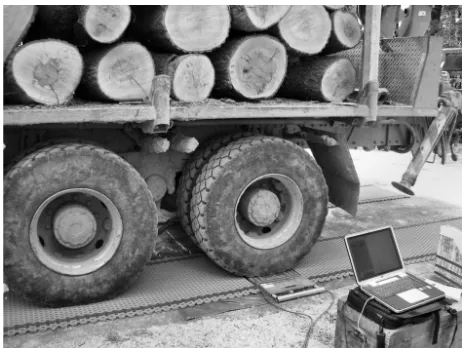
MAN, Fig. 6). Axle configuration, and loaded and un
-loaded axle loads were registered for each truck type. Measurements of axle load were carried out by wheel load scales (Fig. 7).
The precision of the measurements was ±50 kg. The experimental road was loaded intensively. The num
-ber of passing trucks was registered. Different axle loads were converted to 100 kN ESAL by the use of equivalent axle load factors. Based on the weight of timber to be transported and the type of trucks used, traffic (T100) could be calculated. The number of ESAL-s on the experimental road iESAL-s ESAL-shown in Fig. 8. During the test period, 2100 ESAL artificial traffic was applied. Since loading was not continuous, the intensity of traf
-fic was high during the loading periods.
3. Results and discussion
3.1 Bearing capacity modulus of the subgradeAs to all ten experimental sections static E2 values
were tried to be defined. The measurements were made by turns at the centre of every section, and left and right from it, in the line of the expected tracks. Unfortunately, on the wet subgrade the measurement could be success
-fully performed at only two sections. Though these re
-sults agreed quite well with the measurements per
-formed in advance, an average of 10 MPa bearing capacity value was defined on the subgrade.
3.2 Evaluation of the static and dynamic load bearing capacity measurements
After building the lime stabilization, the increase of bearing capacity was studied with two types of model effect (static, dynamic). The data series of the
Fig. 8 Artificial traffic on the experimental section
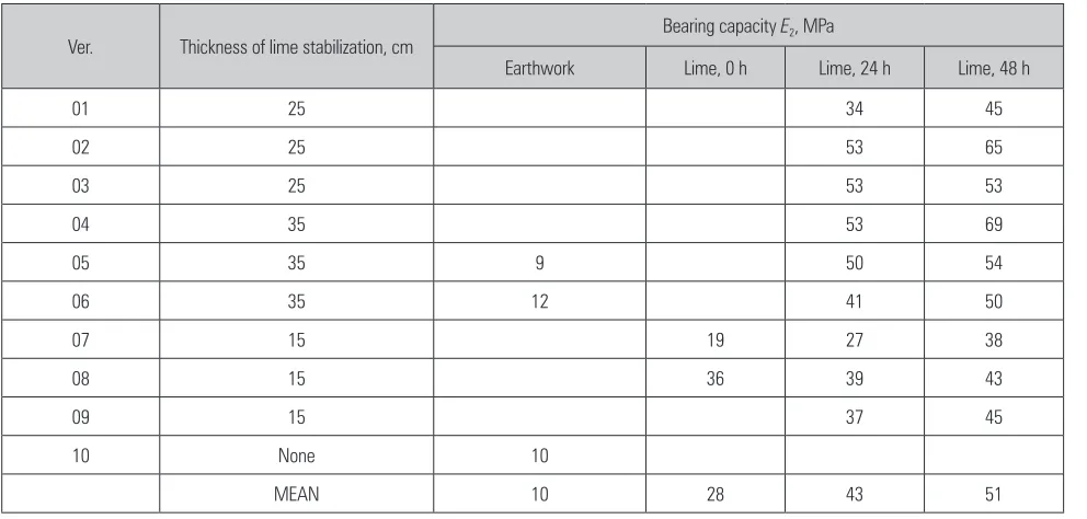
Table 1 Values of the moduli determined by plate bearing tests
Ver. Thickness of lime stabilization, cm Bearing capacity E2, MPa
Earthwork Lime, 0 h Lime, 24 h Lime, 48 h
01 25 – – 34 45
02 25 – – 53 65
03 25 – – 53 53
04 35 – – 53 69
05 35 9 – 50 54
06 35 12 – 41 50
07 15 – 19 27 38
08 15 – 36 39 43
09 15 – – 37 45
10 None 10 – – –
MEAN 10 28 43 51
two types of measurements were intended to define the static modulus necessary for planning, since the current technical regulation contains specifications about this. Apart from the lime stabilization layers, the load bearing capacity changes of the pavements built upon the lime stabilization layers were also studied. Static (E2) and dynamic (Ed) load bearing capacity val
-ues were defined as mentioned above. In pavement versions No. 2 and 7 (Asphalt concrete (AC 22) bind
-ing course with large shear strength), the B&C light drop weight device did not show any excursions, so it was not possible to perform the measurement. During the calculations, the Poisson ratio was μ=0.5. The mea
-surement results are shown in Table 1 and 2.
According to the professional literature, the dy
given (Subert 2005). This topic is detailed in Tompai’s essay (2008). Parallel measurements are needed to de
-fine the threshold limit values typical of the type of material and the conditions on every type of soil, gran
-ular pavement layer, in every case.
The measurements performed on the lime stabili
-zation showed that the load bearing capacity values
defined with different model effects are nearly the same. Fig. 9 clearly shows that both the 24 hours and the 48 hours static (E2), and the average dynamic mod
-ulus (Ed) values show similar results. Therefore, the
load bearing capacity values defined with dynamic model effect can be considered equal to the static E2
needed for planning.
The increase of load bearing capacity of the lime stabilization was followed up through five days with the B&C device. The measurement results are sum
-marized in Fig. 10. According to the measurements, the lime stabilization layer thickness and the increase of load bearing capacity do not correspond. The soil lime reaction is a quite complex process, and there are several factors that affect the rate of load bearing ca
-pacity that are not yet revealed. One of the most prob
-able cause is the high heterogeneity of the soil water content, which can have a significant effect on the reac
-tion of the soil lime mixture. In spite of all this, it can clearly be seen that the highest increase of bearing ca
-pacity was produced in the 25 cm and 35 cm thick lime stabilization experimental sections. During building, the lime stabilization was followed by the spreading and compaction of the crushed stone course, on the surface of which, the load bearing capacity was also measured. The studies performed on the surface of the crushed stone courses showed that the dynamic mod
-uli are ca. twice as much as the static ones.
The static and dynamic load bearing capacity mod
-uli measured parallel on the surface of the completed
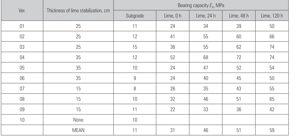
Table 2 Values of the moduli determined by dynamic bearing tests
Ver. Thickness of lime stabilization, cm Bearing capacity Ed, MPa
Subgrade Lime, 0 h Lime, 24 h Lime, 48 h Lime, 120 h
01 25 11 24 34 39 50
02 25 12 41 55 60 66
03 25 15 36 55 62 74
04 35 12 52 68 72 74
05 35 10 24 47 52 54
06 35 9 24 40 45 50
07 15 8 26 35 43 55
08 15 10 32 46 51 65
09 15 11 22 33 36 42
10 None 10 – – – –
MEAN 11 31 46 51 59
pavements do not show correspondence with each other at all. The main cause may be that, while the static load bearing capacity measurement can study a 75 cm thick layer, the detection range of the light drop weight measurement is only 30 cm. Therefore, the dy
-namic measurement is not suitable to study the pave
-ments built of different layers, since it cannot detect the favorable and unfavorable features of the sub
-grade.
3.3 Bearing capacity modulus of lime stabilization layers
The results of the demonstrated static and dynam
-ic load bearing capacity measurements show that the modulus of the lime treated soil layers can be deduced. The built subgrade and the lime stabilization together make a two layer system. Since the load bearing capac
-ity modulus of the cohesive clay subgrade is known (10 MPa), and also the H thickness of the lime treated layers and the (Ee) value of the surface moduli mea
-sured on their surface, the F deflection factor can be calculated using correspondence No. (3). According to the theory of Burmister (1945), the modulus of the H thickness lime treated layer can be defined knowing these parameters (Fig. 5). After the calculations, the modulus of the lime stabilization layers resulted as Elime=500 MPa, which is almost the same as the modu -lus of a well compacted continuous grain distribution
macadam layer. According to this result, the lime treat
-ed soil layers can be count-ed as pavement layers, fur
-ther on.
It is also possible to originate this two layer system in a single layer system, which behaves similarly to the original one, under the same conditions. According to the current public road design regulations, the lime stabilization is counted as improved subgrade, and not as a part of the pavement. In this case, the modulus of the improved subgrade is the equivalent surface modulus (Ee) defined on the surface of the two layer
system. According to the field measurements, this value was defined to three thickness groups:
Hlime=15 cm Eis.=40 MPa Hlime=25 cm Eis.=50 MPa Hlime=35 cm Eis.=60 MPa Where:
Hlime thickness of the lime-treated layer; Eis. modulus of the improved subgrade.
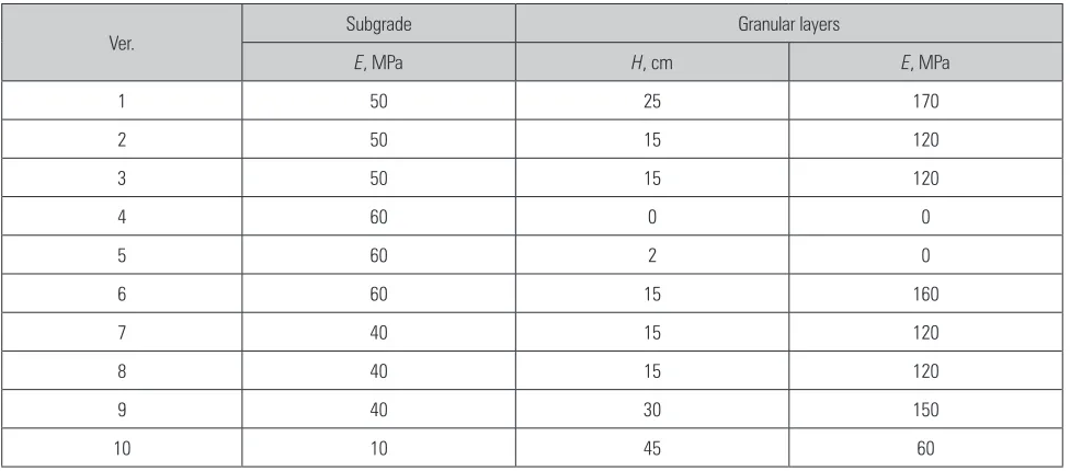
3.4 Load bearing capacity modulus of granular layers
The moduli of the granular layers were estimated with the correspondences by Barker et al. (1977), de
-scribed in point 2.5.3. The lime stabilization layers, as improved subgrade, were introduced into the model.
The results of the calculations are summarized in Table 3. It can clearly be seen that, in the case of the control section, the moduli of the granular layers were the lowest because of inappropriate compaction of the subgrade. At ver. 9 built with the same total thickness (15 cm lime stabilization), the crushed stone layer modulus was 150 MPa, which is more than twice as much as the traditional solution (15 cm sandy gravel). Where the thickness of the lime stabilization is 35 cm, the load bearing capacity modulus of the improved subgrade equals the load bearing capacity of the entire pavement control section.
3.5 Cost of pavements
The estimated bearing capacities of pavement ver. 6 and traditional pavement (the control section) are similar. Therefore, their construction costs could be compared. Both pavement types were built with the same width, therefore their construction costs were calculated per linear meter. The costs are shown in Table 4 on the price level of 2006. Based on this data, it can be stated that, under the given circumstances, the pavement with lime-stabilization was half as ex
-pensive as the traditional one.
3.6 The effect of traffic on experimental road According to the deflection measurements, the fol
-lowings can be stated about the sections after the evaluation of the measurement results and fieldwork. Generally, the experimental sections performed well under traffic load. The experimental pavements got
more or less deformed due to the artificial traffic. The main goal of the Benkelman beam measurements was to determine the deterioration curve of pavements. The central deflection changing was linear compared to the traffic. As a result of one year resting, the pave
-ments of all versions regenerated. The regeneration is clearly visible on the central deflection data (Fig. 11). On pavements with 25 cm and 35 cm thick stabilized courses, deflection values are similar, while higher de
-flection were measured on the ones with 15 cm stabi
-lized courses.
A certain part of the evolved deformations does not correspond to the size of the traffic, but was caused by technological problems. The deterioration of the pave
-ment versions started in 2008. The pave-ment of the control section (ver. 10) was completely deteriorated on the whole length, the 15 cm thick sandy gravel and the 30 cm thick crushed stone layer above it entirely mixed with each other. This huge deformation was already experienced at T100=700 ESAL. The reason was that the sandy gravel and the crushed stone courses were not properly compacted. As an impact of the traf
-fic, under the improperly compacted pavement, the soil failed. Beside the control section, there were three pavement versions where huge deformations evolved not connected to the size of traffic.
On the first Finnish asphalt section (ver. 3), a big rut evolved along the right side track, which is prob
-ably just a local failure. This was confirmed by the statistic process of the deflection measurements. The failure was also predicted during the graphical
Table 3 E moduli of granular layers by pavement versions
Ver. Subgrade Granular layers
E, MPa H, cm E, MPa
1 50 25 170
2 50 15 120
3 50 15 120
4 60 0 0
5 60 2 0
6 60 15 160
7 40 15 120
8 40 15 120
9 40 30 150
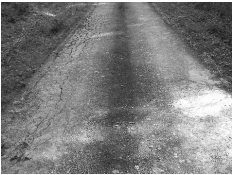
process of the deflection measurements, and later, the failure evolved as a result of the experimental traffic. On the second AC 22 (ver. 7, Fig. 12) section and on the ver. 8 Finnish asphalt section (Fig. 13), there were big and long deformations along the left side track.
The reason is probably a technological problem, again. A part of the crushed stone layer under the as
-phalt layer, because of the improper side support, was
pushed sidelong, and therefore, the asphalt layer got damaged under the large bending strain. The left roadside is narrower than the right one, and the water running away from the asphalt was leaking in at the roadside in greater amount. Exploring the pavement, it became clear that the lime stabilization layer also »broke« under the experimental traffic. The macadam pavements built on lime stabilization were all in good condition after the traffic (Fig. 14).
Table 4 Cost of traditional pavement and a pavement with lime stabilization
Traditional pavement Pavement with lime stabilization
Course thickness Material Cost, €/lm Course thickness Material Cost, €/lm
15 Sandy gravel 11.9 35 Lime stabilization 9.9
35 Crushed stone 27.7 15 Crushed stone 11.9
50 Total 39.6 50 Total 21.8
Fig. 11 Deterioration curves of experimental pavements based on central deflection data
Fig. 13 Left rutting on Finnish asphalt (Ver. 8)
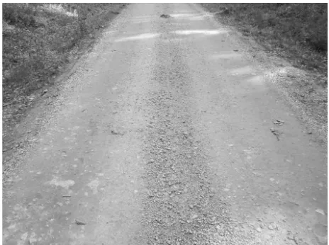
The unsurfaced lime stabilization (ver. 5, Fig. 15) endured the traffic very well so far; the tires erased a 1 cm thick layer from the surface, therefore, a certain depth of rut evolved, though far from the level it could be objected. Bigger cracks could be observed on the surface, as recorded on photos.
4. Conclusions
A test road was built to examine the effects of lime stabilized soil as subgrade. As expected, the applied lime increased the bearing capacity of the original co
-hesive soil. When designing a pavement with lime stabilized medium clay subgrade, it can be taken into account with a 500 MPa layer modulus. Doing so, the required bearing capacity can be reached with smaller amount of additional building materials. Therefore,
transportation and construction costs as well as envi
-ronmental impacts can be reduced. In order to get sat
-isfactory performance from the pavements built on cohesive soil, 25–35 cm of lime stabilized subgrade should be designed to support them. For low traffic roads, 35 cm of stabilized local soil with a thin (15 cm) crushed stone surfacing could be enough to provide trafficability. 25–35 cm thickness can be constructed in one stage of mixing if the constructing machine is ap
-propriate. For mixing, it is necessary to apply a special rotary mixer machine, or a mixing adapter attached to an agricultural tractor with 150 kW output power.
Based on the experiences gained from the road tests, a 6 km long forest road was built with stabilized local cohesive soil as subgrade. It was confirmed that pavements built on stabilized cohesive soil are durable only if appropriate drainage is provided.
Acknowledgements
The experimental road was built as collaboration between the Regional Knowledge Centre of Forest and Wood Utilization (ERFARET), the Institute of Geomat
-ics and Civil Engineering of the University of West Hungary, the Carmeuse Hungary Ltd. and the Zalaerdő Forestry Company. Research work of Péter Primusz was supported by the European Union and the State of Hungary, co-financed by the European Social Fund in the framework of TÁMOP-4.2.4.A/2-11/1-2012-0001 »National Excellence Program«. Previous research for this research project: Péter Pázmány programme (RET-03/2004), 1.3. Technical development of forest manage
-ment, Development of forest opening up networks. The project completion date: 2006–2008.
5. References
Barker, W.R., Brabston, W.N., Chou, Y.T., 1977: A General Sys
-tem for the Structural Design of Flexible Pavements. Proceed
-ings of the Fourth International Conference on the Structural Design of Asphalt Pavements, Ann Arbor: 209–248.
Behak, L., 2011: Performance of full-scale test section of
low-volume road with reinforcing base layer of soil-lime. Trans
-portation Research Record, Journal of the Trans-portation Research Board 2204: 158–164.
Bocz, P., Devecseri, G., Fi, I., És Pethő, L., 2009: Pályas
-zerkezetek analitikus méretezése. Közlekedésépítési szemle 59(5): 8–22.
Burmister, D.M., 1945: The General Theory of Stresses and Displacements in Layered Soil Systems. Journal of Applied Physics 16(2): 89–94.
Claussen, A.I.M., Edwards, J.M., Sommer, P., Ugé, P., 1977: Asphalt Pavement Design. The Shell Method. Proceedings of
Fig. 14 Macadam pavement built on lime stabilization (Ver. 6)
the Fourth International Conference on the Structural Design of Asphalt Pavements, Vol. I, Ann Arbor: 39–74.
Highway Research Board 1961: The AASHO Road Test, Highway Research Board Special Report 61A, National Academy of Sciences: Washington, D.C. 56 p.
Huang, Y.H., 2003: Pavement Analysis and Design, Second Edition, Prentice Hall, ISBN-13: 9780131424739, 792 p. Kosztka, M., 1989: A Makk-pusztai kísérleti úton végzett
megfigyelések a vékony útpálya-szerkezetek tönkremene
-telének folyamatáról. Erdészeti és Faipari Tudományos Kö
-zlemények 2: 25–36.
LeBel, L., Doré, G., Provencher, Y., 2000: Laval University’s full-scale experimental site for construction and maintenance of forest roads. Proceedings of the COFE-CWF Conference. 11–14 September, Kelowna, British Columbia, Canada. Little, D.N., 1995: Handbook for stabilization of pavement subgrades and base courses with lime. Lime Association of Texas, USA.
Metcalf, J.B., 1996: NCHRP Synthesis of highway practice: Application of full-scale accelerated pavement testing. TRB, National Research Council, Washington D.C., USA.
National Lime Association (NLA) 2004: Lime-treated soil construction manual. National Lime Association, USA.
Nemesdy, E., 1985: Útpályaszerkezetek méretezésének és anyagállandó-vizsgálatainak mechanikai alapjai. Kutatási részjelentés I., BME Útépítési Tanszék, Budapest.
Nemesdy, E., 1991: A zúzottkőalapok és kavicsalapok szerepe
és hatékonysága az új út-pályaszerkezetekben. Közlekedé
-sépítés- és Mélyépítéstudományi Szemle 41(7): 241–253. Papagiannakis, A.T., Masad, E.A., 2008: Pavement Design and Materials, Wiley&Sons, Hoboken NJ, ISBN-10: 0471214612, ISBN-13: 978-0471214618, 552 p.
Subert, I., 2005: A dinamikus tömörség- és teherbírásmérés újabb paraméterei és a modulusok átszámíthatósági kérdése. Közúti és mélyépítési szemle 55(1): 5.
Szendefy, J., 2013: Impact of the soil-stabilization with lime.
Proc. of the 18th International Conf. of ISSMGE Paris: 2061–
2064.
Tárczy, L., 2007: Meszes talajkezelés. Közúti és mélyépítési szemle (2): 26–28.
Tompai, Z., 2008: Földművek és kötőanyag nélküli alapré
-tegek teherbírásának és tömörsé-gének ellenőrzése könnyű ejtősúlyos módszerekkel. Budapesti Műszaki és
Gazdaság-tudományi Egyetem, Építőmérnöki Kar, Ph.D. theses, Buda
-pest, 162 p.
Yoder, E.J., Witczak, M.W., 1975: Principles of Pavement De
-sign, Second Edition, John Wiley & Sons, Inc. ISBN: 9780471977803, 711 p.
Received: April 30, 2014 Accepted: October 06, 2014
Authors’ address – Adresa autorâ: Assoc. prof. József Péterfalvi, PhD.* e-mail: [email protected] Assist. prof. Péter Primusz, PhD. e-mail: [email protected] Assoc. prof. Gergely Markó, PhD. e-mail: [email protected] Balázs Kisfaludi, MsC.
e-mail: [email protected] Prof. emerit. Miklós Kosztka, CSc. e-mail: [email protected] University of West Hungary
Faculty of Forestry
Department of Forest Opening Up
Institute of Geomatics and Civil Engineering Bajcsy-Zsilinszky u. 4.
Sopron, 9400 HUNGARY