Evaluation of a New Energy Recycling
Hydraulic Lift Cylinder for Forwarders
Jussi Manner, Ola Lindroos, Hans Arvidsson, Tomas Nordfjell
Abstract
In mechanized forestry, much of the work is conducted by use of cranes, and recovering po-tential energy is a possible method to reduce energy consumption when using cranes for lift work. The objective of this study was to evaluate the capacity of a new »Energy-efficient hy -draulic lift cylinder« (EHLC), which has a secondary cylinder built into its piston rod, to store potential energy from lowering the boom in the form of pressurized hydraulic oil in an accu-mulator and using the stored energy in the next boom lift. The EHLC was mounted on a forwarder, and manipulated to enable its use also as a standard cylinder. We then compared the EHLC and a standard cylinder in terms of function and energy consumption during re -petitive boom lifts and lowerings. With the tested settings the EHLC saved up to approxi -mately 9.4% of the energy consumed during the first part of boom lifts and up to 3.2% of the total lift energy. With possible further adjustments, such as optimization of the accumulator size, enlargement of the assisting cylinder diameter, and enhancement of the accumulator pressurization, but most importantly reduction in internal leakage, the current EHLC could have commercial potential.
Keywords: weight-balancing, fluid dynamics, fluid mechanics, timber loader, mobile hydrau -lic lift devices, Boyle’s law, counterweight
1. Introduction
Increases in energy costs and environmental con-cerns have intensified efforts to improve energy effi -ciency recently, both generally and specifically in en -gineering research (e.g. European Union 2014, United Nations 2014). Notably, several recent studies have ad -dressed possible methods to improve the productivity of cranes used in harvesters, planting machines and forwarders (Lindroos et al. 2008, Jundén et al. 2013, Laine and Rantala 2013, Ersson et al. 2014, Ortiz Mo -rales et al. 2014). Cranes are used primarily for lift work, in many mobile and stationary applications, which involves relocating objects in such a manner that their potential energy changes. Consequently, re -covering potential energy can probably be used to re -duce the energy required for the work (e.g. Liang and Virvalo 2001a, Sun and Virvalo 2003, Rydberg 2005, Sun and Virvalo 2005, Virvalo and Sun 2005, Lin et al. 2010, Lin and Wang 2012, Minav et al. 2012, Noréus et al. 2013, Wang et al. 2013). Forwarder cranes are de -signed to provide large lifts and heights, partly at the
cost of slow horizontal movements (Malmberg 1981, Gerasimov and Siounev 1998, 2000, Virvalo and Sun 2005). Knuckleboom cranes are normally used on for -warders, and consist of a system of hydraulic cylinders and mechanical levers, i.e., a swivelling crane pillar, pivoting mid and outer booms, and an extension boom (Gerasimov and Siounev 2000). While boom is often used as a synonym for crane, that usage is avoided in this paper to avoid confusion between the system and its components (cf. Lindroos et al. 2008).
The action of a vertical lift is mainly executed by an angular change in the joint between the crane pillar and mid-boom, which causes the outer and extension booms to rise. However, in this paper the outer and extension booms are treated as rigid parts of the mid-boom. Thus, boom is used hereafter as a collective term for the mid-, outer and extension booms, with the understanding that lifts are executed via action at the joint between the crane pillar and mid-boom.
-220 Croat. j. for. eng. 37(2016)2 warder productivities range from 11 to 25 m3 per pro
-ductive machine hour, and are negatively correlated with transportation distance, while positively corre -lated with sizes of both logs and loads (Eriksson and Lindroos 2014). Logs are lifted while loading and un -loading the forwarder’s bunk. The total time required to forward a load (for which loading and unloading collectively account for about 60%) is typically 45 min -utes (Manner et al. 2016). Typically, loading and un -loading will require approximately 30 and 20 lifts with a full grapple, respectively (Manner et al. 2013, Man -ner et al. 2016).
The boom on a standard forwarder crane is lifted with a single acting cylinder. Pressurized oil is direct -ed into the cylinder, creating a force that causes the piston rod to lift the boom. To lower the boom, the pressurized oil from the cylinder is released into the non-pressurized reservoir, and no energy is recovered. However, there are several possible methods to save energy, for example, through weight-balancing, a com -mon principle for recovering potential energy during load lowering for cranes and elevators. In a weight-balancing system, some of the potential energy is re -covered and stored during load lowering, and then used to assist the next load lift. The potential energy recovery process creates a braking force that reduces the load lowering speed. Thus, the weight-balancing is a trade-off between the additional lift force and braking force. In a fully balanced system, ignoring en-ergy losses through friction, it is theoretically possible to recover almost all of the potential energy, allowing a load to be lifted and lowered with minor energy in -put. Other examples of the weight-balancing tech -nique for mobile devices are the use of counterweights or coil springs (e.g. Gawlik and Michałowski 2008, Deepak 2012, Lin et al. 2013).
The few available energy recovering lift applica -tions for forest machine cranes are typically based on the use of a hydro-pneumatic accumulator tank (ac -cumulator), a common weight-balancing technique (e.g. Liang and Virvalo 2001a, Liang and Virvalo 2001b, Sun and Virvalo 2003, Sun and Virvalo 2005, Virvalo and Sun 2005). An accumulator consists of a vessel and bladder which separates an inert gas (e.g. nitrogen) from hydraulic oil. The flow of pressurized oil into the accumulator charges the accumulator as the sealed inert gas compresses according to Boyle’s law and, similarly, the flow of oil out from the accu -mulator discharges the accu-mulator and releases the stored energy (during boom lift and boom lowering, respectively, in crane work). Fast charging and dis -charging are some of the advantages of accumulators for energy storage (Hui and Junqing 2010, Minav et al.
2012, Van de Ven 2013). Moreover, accumulators re -duce pressure spikes in the hydraulic system (e.g. Malmberg 1981, Ingvast 1989, Kim et al. 2013, Van de Ven 2013). Experiments show that 21–59% of poten -tial, kinetic or rotational energy can be recovered by using accumulators (Zhang 2011, Ho and Ahn 2012). However, an energy recovery system based on an ac-cumulator also has limitations. Notably, in most sys-tems the accumulator pressure must exceed the pres -sure in the hydraulic circuit to enable reuse of the stored energy (cf. Einola 2013), but the accumulator pressure might decrease below this pressure due, for example, to internal leakage somewhere, which is likely to occur in all hydraulic systems (Manring 2005). Thus, leakage compensation to re-pressurize the ac -cumulator is required. Another limitation is the low energy storage capacity in relation to their size (e.g. Van de Ven 2013).
2. Materials and methods
2.1 The energy-efficient hydraulic lift cylinder
(EHLC)
Technical principles and claims for a flawlessly functioning EHLC (Fig. 1) mounted on a forwarder
Fig. 1 Thordab AB’s patented »Energy-efficient hydraulic lift cylinder« (EHLC) with a pressure accumulator tank (accumulator), a movably arranged secondary piston (a) that divides the cylinder system into primary (b) and secondary cylinders (c). The secondary cylinder is built inside the primary piston rod (d) and connected to the accumulator. Load cell1 (p1) measured the pressure in the standard cylinder and
primary cylinder of the EHLC. Load cell2 (p2) measured the secondary
crane are described below based on the manufactur-er’s information (cf. WIPO Patent WO/2011/075034).
In the starting position, the secondary piston (a) is inside the primary piston rod (d), basically forming a standard cylinder (Fig. 2: panel 1). Immediately after the machine has started and during the first boom lift the pressure in the hydraulic circuit of the accumulator will be the same as in the circuit of the standard cylin-der. However, during boom lowering the accumulator is further pressurized, the check-valve prevents an out -flow and the standard cylinder turns into primary (b) and secondary (c) cylinders (Fig. 1 and Fig. 2: panel 2)
due to the pressure differences. As a result, the second -ary piston will move in the direction of the lower pres -sure at any given time, since both of the secondary piston ends have the same area (Figs. 1–2). Hence, the following lift work will be conducted with assistance from the accumulator, provided that the pressure in the accumulator and secondary cylinder (p2) is higher than in the primary cylinder (p1). If not, the cylinder will function as a conventional cylinder.
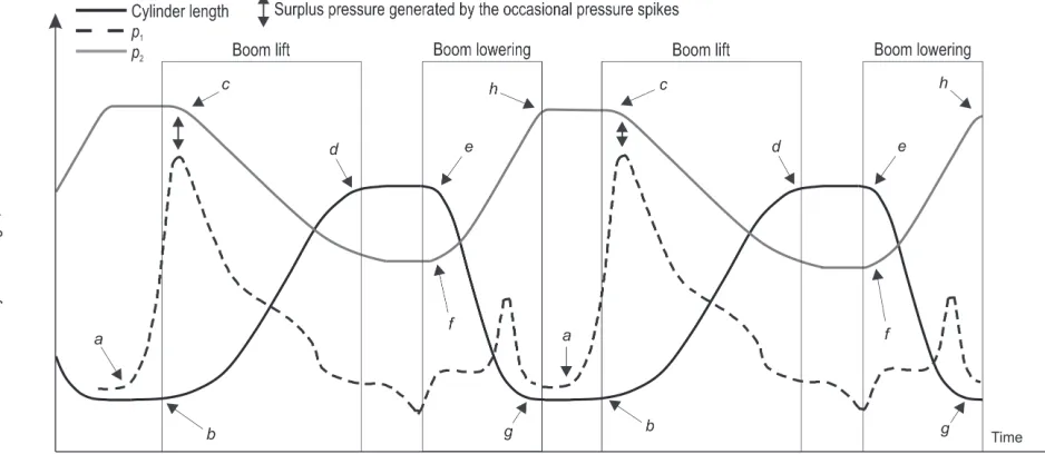
Given that p2 is higher than p1, the product of p2 and the secondary piston area (A2) create a secondary cyl -inder force (F2) (see details in Figs. 1–2). As the second -ary piston thrusts the prim-ary cylinder head continu -ously with a F2 that depends on p2, it creates an assisting force during boom lifts and a braking force during boom lowering. During boom lifting, the ac -cumulator discharges and decreases p2, while a boom lowering charges the accumulator and p2 increases (Fig. 3). Thus, F2 decreases the EHLC'sneed for exter -nal energy input.
Some losses in p2 are likely to occur due, for in-stance, to oil leakage from the secondary to the pri -mary cylinder. If p1 exceeds p2 the check-valve opens and the accumulator will be charged from the hydrau-lic circuit system (Fig. 1). Therefore, a higher pressure must be maintained in the accumulator and secondary cylinder than in the primary cylinder to get an assist -ing force dur-ing a boom lift. Occasional pressure spikes in the hydraulic circuit pass the check-valve and load the accumulator, to 25–30 MPa according to the patent. Thus, occasional pressure spikes that always appear in ordinary hydraulic systems (Manring 2005), and hence occasional short-term check-valve openings are essential contributions to the EHLC's functionality because they maintain a higher p2 than p1 during boom lifts, and also provide leakage compensation (Fig. 3). In addition, the secondary cylinder work (W2) increas -es with increasing p2, thereby decreasing the need for an external energy input. Thus, check-valve openings caused by occasional pressure spikes should not be confounded with »malfunctions« of the EHLC, i.e. regularly open check-valve.
The standard and secondary piston diameters of the studied EHLC cylinder were 124.5 mm and 32.0 mm, respectively (Roger Gustavsson, Thordab AB). This provides a standard piston area (Asp) of 12,174 mm2, A2 of 804 mm2, and a primary piston area (A1) of 11,370 mm2 (Fig. 2). The accumulator volume was 1.0 litre (Roger Gustavsson, Thordab AB).
Based on these specifications, the theoretical en -ergy saving is 6.6–6.9%, given that A2/Asp≈0.066, and
p2 is in the range of 1.00 to 1.05 times p1 during the entire boom lift.
Fig. 2 Panel 1: a standard cylinder. Panel 2: EHLC. In both panels:
a is a movably arranged secondary piston, b is the primary cylinder,
222 Croat. j. for. eng. 37(2016)2
2.2 Test and measure procedure
An EHLC was mounted on a standard Gremo 1050 F forwarder (engine power 120 kW, hydraulic working pressure 23.5 MPa) equipped with a Cranab FC80 crane (boom mass 890 kg), a standard rotator (56 kg), and a Cranab CR280 grapple (200 kg). The experiment took place between the 11th and 13th of July 2011 in Umeå, Northern Sweden.
The mid and extending booms were mechani -cally blocked in positions that gave a constant crane reach of 5.7 m. During the experiment, the boom was lifted and lowered by actuating the lift cylinder di -rectional control valve using a joystick. Three set-tings for the valve response to the joystick actuations were used, resulting in different directional control valve opening speeds for the same joystick move -ment and hence different acceleration and boom speeds, designated slow, medium and fast (Table 1). A boom lift with »slow« valve setting was followed by a boom lowering with »slow« valve setting and so on. When actuated, the joystick was pushed to extremity with a fast movement. At end destinations of the boom (lifted and lowered), the joystick was released back to the neutral position for at least 5 seconds to ensure pressure stabilization in the hy -draulic circuit.
The boom tip position varied from approximately 1.5–4.5 m above ground during a lift cycle. The opera -tor (a 31 year-old male with no previous experience of work with heavy machinery) tried to keep the lift heights constant throughout the experiment. Initial and final cylinder lengths (Fig. 1) were documented (Table 1), and the possible effects of their variation on the results were reduced statistically (see chapter, »2.3 Statistical analysis«).
By closing and opening certain valves in the hy -draulic system, the accumulator could be overridden. When it was overridden, the EHLC functioned as a standard hydraulic lift cylinder (standard cylinder) providing a reference cylinder for comparisons of energy use (Fig. 2: panel 1).
Pressure observations (p1 and p2) were recorded by Bofors TDS-1 load cells (error ±500 kPa) (Fig. 1). Both of the load cells used were calibrated with a Barnet Instruments dead weight tester once at the beginning of the experiment. The cylinder length sen -sor used (error ±2.3 mm) was based on a 10 turn 1 kΩ potentiometer. Data from load cells and the cylinder length sensor were recorded 105 times per second us
-ing a DEWE 2520 datalogger with an integrated com -puter running the DEWEsoft 6.5 program.
A general model for determining lift work during a given time interval (Wt®t+1) (Eq. 1) was used as a start-ing point for calculatstart-ing the work conducted by the two cylinders.
Wt®t+1= 0.5 ´ (pt + pt+1) ´Apiston´ (Lt+1 – Lt) (1)
Where:
p the cylinder pressure at time t or t+1,
Apiston piston area,
L is the cylinder length at time t or t+1.
The work conducted during a given boom lift was calculated by dividing the lift into 105 time intervals
per second and summing the work for all time inter -vals.
The standard cylinder's lift work during time interval from t to t+1 (Ws, t®t+1) was calculated based on Eq. 1, with p1 used for pressure (i.e. the pressure observations retrieved from load cell1, Fig. 1), and Asp as piston area
(Fig. 2: panel 1). Calculation of the functioning of EHLC’s lift work in a technically perfect state (WEHLC, t®t+1) was based on p1 and A1 as piston area (Fig. 2: panel 2). How -ever, the EHLC might not work perfectly; a possible condition being when p1 might exceed p2 during part of the lift.
In this study, the part of a lift where p1<p2 is referred to as the EHLC's »successful lift phase« (Fig. 4: t1®t2), because during this phase the EHLC is theoretically capable of contributing to the lift with recovery energy. Similarly, the »unsuccessful life phase« refers to the part of the lift after which p1>p2 for the first time and the EHLC will not be able to contribute to reductions in energy use.
Lift work calculations for the EHLC’s successful lift phase were identical to the calculations for flawless functioning of the EHLC. However, work calculations for EHLC’s unsuccessful lift phase varied depending on whether p1 or p2 was highest. For time intervals with
p1>p2 the EHLC was assumed to function as a standard cylinder and work was determined correspondingly (Ws, t®t+1). For time intervals with p1<p2 during the un-successful lift phase, the EHLC's work was determined as the sums of WEHLC, t®t+1 and the secondary cylinder lift work (W2, t®t+1), given that regaining the EHLC's func -tionality was a result of accumulator being loaded from the hydraulic circuit during the lift (i.e. consuming en -ergy), and not by using the recovered potential energy.
W2, t®t+1 was calculated according to Eq. 1 with p2 used as pressure and A2 as the piston area (Fig. 2: panel 2).
Table 1 Initial and final lift cylinder lengths, stroke lengths, lift times and average piston velocities during boom lifts for each combination of lift cylinder model (cylinder model), payload and directional control valve setting (valve setting). Mean values, with standard deviations in parenthesis
Payload
kg settingValve Cylinder model Observations n Initial cylinder length mm Final cylinder length mm Stroke length mm Lift time s Piston velocity mm/s
0
Slow Standard 25 1093 (1) 1213 (3) 121 (3) 4.6 (0.1) 26.1 (0.3) EHLC 27 1091 (1) 1211 (3) 120 (3) 4.6 (0.1) 26.1 (0.3)
Medium Standard 34 1093 (3) 1223 (5) 130 (4) 1.7 (0.1) 77.4 (2.5) EHLC 32 1091 (3) 1219 (8) 128 (8) 1.7 (0.1) 76.7 (2.7)
Fast Standard 57 1092 (6) 1223 (5) 131 (5) 1.5 (0.1) 85.5 (2.4) EHLC 34 1096 (8) 1224 (9) 128 (12) 1.5 (0.1) 84.1 (3.2)
264
Slow Standard 21 1113 (1) 1228 (2) 116 (2) 7.7 (0.2) 15.0 (0.2) EHLC 22 1113 (1) 1229 (2) 117 (2) 7.9 (0.2) 14.8 (0.2)
Medium Standard 20 1111 (3) 1234 (10) 123 (12) 1.8 (0.1) 68.8 (3.0) EHLC 27 1114 (5) 1233 (6) 119 (9) 1.8 (0.1) 64.7 (1.5)
Fast Standard 26 1037 (12) 1173 (8) 136 (15) 1.9 (0.2) 71.3 (2.6) EHLC 27 1093 (9) 1236 (10) 144 (16) 2.0 (0.2) 72.6 (1.9)
513
Slow Standard 15 1095 (1) 1213 (1) 118 (2) 20.6 (0.6) 5.7 (0.1) EHLC 18 1094 (3) 1213 (1) 119 (3) 19.3 (1.0) 6.2 (0.2)
Medium Standard 20 1060 (9) 1220 (8) 160 (13) 3.9 (0.4) 41.6 (2.6) EHLC 20 1066 (6) 1229 (9) 162 (9) 3.5 (0.2) 46.2 (1.8)
224 Croat. j. for. eng. 37(2016)2 The energy savings for the EHLC's successful lift phase
were determined as the secondary cylinder proportion of the EHLC's total work during the successful lift phase, which in turn was determined as the sum of the primary and secondary cylinder work.
2.3 Statistical analysis
The statistical analysis included only boom lifts, as boom lowerings were excluded. Analysis of covari -ance (ANCOVA) was used to evaluate effects of three fixed factors (lift cylinder model, payload, and valve setting) on two dependent variables: total work per lift and the initial p1, retrieved from a load cell1 (Fig. 1). The factor cylinder model had two levels ‒ EHLC and standard cylinder, while the factor payload had three levels ‒ objects with the mass 0, 264 and 513 kg ‒ held in the boom tip. Finally, the factor valve setting had three levels: slow, medium and fast (Table 1). In total, this resulted in 18 treatments, which were each repli -cated several times (15≤n≤57, Table 1). The three-fac -torial model contained all possible interaction effects between factors.
Covariates were used if they significantly contrib -uted to the model, and were considered logical and not risked to be confounded with treatment effects. In this experiment, the continuous variables ‒ initial and final cylinder length, stroke length and lift time ‒ were used as covariates for each boom lift. To avoid a rank
deficiency, the initial and final cylinder lengths were prioritized over the stroke length. The stroke length effect was tested only if the initial or final cylinder length had no effect.
In addition to the dependent variables mentioned above, the EHLC was also evaluated separately to ad -dress its functionality (i.e. without comparison between cylinder models). For such analyses all the cylinder model-related terms were removed from the three-way ANCOVA, resulting in a two-way ANCOVA with the fixed two-way interaction effect: payload ´ valve set-ting. The dependent variables analyzed were related to pressure in the primary and secondary cylinders as well as work and time during the successful lift phase.
The order between treatments was randomized, but all replicates within a treatment were conducted sequentially. However, the first 10 boom lifts within each treatment were excluded from the analysis to en -sure that the system had stabilized in terms of oil pres -sure and temperature during the data collection.
A general linear model (GLM) was used to analyze the analysis of variance (ANOVA) and ANCOVA mod -els. During the GLM procedure, pair-wise differences were analyzed with Tukey’s simultaneous test of means. The normality of residuals was evaluated by the Ander -son-Darling test. Differences in initial cylinder pres -sures within the EHLC were tested for deviation from
Fig. 4 Example of observed pressures and cylinder lengths as a function of time for one whole EHLC boom lift cycle (t1®t7) with the valve setting »medium« and payload of 0 kg. The boom lift, as well as the successful lift phase, starts at time t1. The successful lift phase ends at
zero by use of a one-sample t-test. The critical level of significance was set to 5%. Minitab 16 (Minitab Ltd.) was used for all analyses.
3. Results
The EHLC's functionality is dependent on the pres -sure in the secondary cylinder exceeding the pres-sure in the primary cylinder (p1<p2, Figs. 1–2). However, this was found to never occur during a full lift, but only during various intervals of the first part of the boom lift, which varied from repetition to repetition (Fig. 4:
t1®t2). Moreover, p2 and p1 were practically identical during the whole lift when using the valve setting »slow« (no data shown).
For valve settings »medium« and »fast«, the EHLC's
p2 level surpassed p1 in the beginning of a lift (Fig. 4). During this »successful lift phase« (Fig. 4: t1®t2), the accumulator contributed recovered energy from the preceding lift. During the next boom lowering, the ac -cumulator was loaded as p1<p2 (Fig. 4: t4®t5). When p2 exceeded approximately 30 MPa, the accumulator stopped charging, indicating that the pressure relief valve was released at that pressure (Fig. 4: t5®t6).
3.1 Comparison of cylinder models for whole lifts
The three main factors – the cylinder model, pay -load, and valve setting – significantly affected both of the two dependent variables initial p1 and the energy
Table 2 Levels of significance (p-values) and explained variance (R2 adjusted values) obtained from the analysis of variance (ANOVA) of:
effects on the dependent variables listed in the first column of the factors cylinder model (a), payload (b) and valve setting (c); their fixed interaction effects (a´b, a´c, b´c and a´b´c); and effects of the covariates initial lift cylinder length (d), final lift cylinder length (e), lift time (f) and stroke length (g)
p-value
Adj. R2
% n
Dependent variables Factor Covariate
a b c a×b a×c b×c a×b×c d e f g
Energy consumption per whole lift <0.001 <0.001 <0.001 <0.001 <0.001 <0.001 <0.001 <0.001 <0.001 <0.001 – 99.7 473
Initial p11) <0.001 <0.001 <0.001 <0.001 <0.001 <0.001 <0.001 Excl. – – – 83.8 473
Initial p21) – <0.001 <0.001 – – <0.001 – <0.001 – – – 99.6 229
Difference between initial p2 and initial p1 – <0.001 <0.001 – – <0.001 – Excl. – – – 94.4 229
Number of p2 and p1 intersections per lift – <0.011 <0.001 – – <0.001 – <0.001 Excl. Excl. Excl. 73.3 229
W21) during the successful lift phase – <0.001 <0.001 – – <0.001 – Excl. – – – 76.6 162
W11) during the successful lift phase – <0.001 <0.001 – – <0.001 – Excl. – – – 78.2 162
Relative energy saving for successful lift
phase2) – <0.001 0.068 – – <0.001 – Excl. – – – 43.7 162
Successful phase stroke length – <0.001 <0.001 – – <0.001 – Excl. – – – 76.0 162
Successful phase proportion of total
stroke length – <0.001 <0.001 – – <0.001 – Excl. 0.005 – Excl. 76.5 162
Successful phase lift time – <0.001 <0.001 – – <0.001 – 0.011 – – – 88.6 162
Successful phase proportion of the total
lift time – <0.001 <0.001 – – <0.001 – Excl. 0.002 – Excl. 78.3 162
n£229 when only the EHLC treatments were included, and n=162 when only the EHLC treatments with medium and fast directional control valve settings were included – independent variable was not tested
Excl. covariate term was tested, but excluded from the model because it had no effect (p>0.05) or it decreased adj. R2-value 1)p
1 primary or standard cylinder pressure (depending on cylinder type) p2 secondary cylinder pressure (only EHLC)
W2 secondary cylinder work W1 primary cylinder work 2) W
226 Croat. j. for. eng. 37(2016)2 consumption per full lift (three-way ANCOVA,
p<0.001, Table 2: rows 1–2). As expected, most of the discrepancies between the two dependent variables were explained by the payload, while the valve setting and cylinder model only had minor effects (data not shown). The initial p1 was not affected by the only tested covariate ‒ the initial cylinder length (three-way ANCOVA, p=0.774, Table 2: row 2, complete data not shown). On the other hand, the energy consumption per lift was affected by all the recorded covariates: the initial and final cylinder length, and lift time (three-way ANCOVA, p<0.001, Table 2). Overall, the total energy consumption model was improved most by inclusion of the initial cylinder length, followed by the final cylinder length. The lift time had least effect (data not shown).
The EHLC's initial p1 increased significantly (p<0.001) with increasing payload across all the three valve set -tings (Table 3). However, the standard cylinder's initial
p1 increased significantly (p<0.001) with increasing payload only across the valve setting »fast«. In addi -tion, there was a lack of statistically significant differ -ences between the treatments when the payload ef -fects were compared over the valve settings »slow« and »fast«. This resulted in significant (p<0.001) two- and three-way interaction effects (Tables 2–3).
As expected, the energy consumption per lift for both cylinder models increased significantly (p<0.001) with increasing payload across all three valve settings (Table 3). The valve settings significantly (p<0.05) af -fected EHLC'senergy consumption with payloads of 0 and 513 kg, but had no significant effect with the 264 kg
Table 3 Pressure and energy consumption for a whole lift with EHLC and standard cylinder for each combination of payload, valve setting and cylinder model. Mean values, with standard deviations in parenthesis
Payload kg
Valve setting
Cylinder model
Initial p11)
kPa
Initial p2
kPa
Difference between initial p2 and initial p12),
kPa
Number of p2 and p1
intersections during the whole lift, n
Energy consumption per whole lift, J
Observations
n
0
Slow Standard 14,182
DE (304) – – – 18,992EF (346) 25
EHLC 13,068E (98) 12,591G (129) –479F (81) 47.5A (18.9) 19,330E (410) 27
Medium Standard 13,264
E (2617) – – – 18,257F (551) 34
EHLC 10,464F (1670) 24,374ABC (465) 13,909A (1912) 5.1C (2.3) 17,669G (1340) 32
Fast Standard 13,105
E (2698) – – – 18,400F (712) 57
EHLC 9791F (777) 21,637D (400) 11,767B (762) 11.7BC (4.4) 18,488EF (1573) 34
264
Slow Standard 18,328
BC (524) – – – 28,514C (388) 21
EHLC 17,588C (208) 16,863F (195) –1053F (93) 11.8BC (3.1) 28,186C (465) 22
Medium Standard 21,647
A (2163) – – – 27,390C (2423) 20
EHLC 14,985D (1154) 24,516AB (180) 9178C (1208) 23.4B (3.4) 27,185C (1663) 27
Fast Standard 15,167
D (936) – – – 23,064D (3010) 26
EHLC 15,262D (576) 24,152C (211) 8870C (506) 14.5BC (6.0) 27,172C (3294) 27
513
Slow Standard 19,859
AB (145) – – – 36,164AB (475) 15
EHLC 20,043AB (115) 19,868E (121) –227F (33) 18.4B (7.9) 35,642AB (841) 18
Medium Standard 21,142
A (1725) – – – 32,773A (3214) 20
EHLC 19,928AB (2417) 24,655A (282) 5119D (2081) 24.4B (11.0) 32,097B (2107) 20
Fast Standard 20,518
A (2047) – – – 32,763A (4298) 26
EHLC 21,662A (1896) 23,974BC (244) 2909E (1373) 58.3A (21.9) 32,720A (2269) 22
Within columns, different superscript letters indicate significant differences (p<0.05). Statistical models are described in Table 2
1)p
1 pressure recorded in load cell1 (Fig. 1), i.e. in the primary EHLC cylinder and standard cylinder p2 pressure recorded by load cell2, i.e. in the accumulator circuit and the secondary cylinder
payload. In contrast, the standard cylinder's lift energy consumption was significantly affected by the valve settings with the 264 kg payload, but not with the 0 and 513 kg payloads. This resulted in significant (p<0.001) two- and three-way interaction effects (Tables 2–3).
3.2 Evaluation of the EHLC's successful and unsuccessful lift phases
In addition to the initial p1 and energy consump -tion per full lift, the EHLC's successful lift phase was further analyzed with supplemental dependent vari -ables (Table 2: number of observations in the range of 162–229). The two main factors, payload and valve set -ting, significantly (p<0.001) affected all the supplemen -tal dependent variables, when data for all three valve settings were included in the analyses (Table 2). The initial p2, and number of intersections of p2 and p1 per lift, were also significantly affected by the covariate initial cylinder length (p<0.001) (Table 2). The signifi -cant (p<0.001) interaction effects showed that the fac -tors effects varied between the compared treatments, and occasionally, the interaction effect was the result of a lack of differences between the compared treat -ments (Tables 2–3).
With the valve setting »slow«, the initial p1 was sig-nificantly higher than p2 (Table 3), thus the possibilities of energy recovery were eliminated even before the boom was lifted. Consequently, only data obtained with the valve settings »medium« and »fast« were fur -ther analyzed. With these settings, the initial p2 was substantially higher than the initial p1, which enabled energy recovery (Table 3). The payload and valve set
-ting significantly (p<0.05) affected all except one de -pendent variable in EHLC's successful lift phase (Ta -ble 4). The exception, which fell just outside the set level for significance, was that the relative energy savings for EHLC's successful lift phase was not affected by the valve setting (p=0.068) (Table 2). In addition, the valve settings had a significant (p<0.05) effect on the depend -ent variables with the 0 kg payload, but not with the 264 or 513 kg payloads (Table 4). This resulted in sig -nificant two-way interaction effects (p<0.001, Table 2).
The EHLC's successful lift phase corresponded to 9.3–10.2% of the total lift time when lifting a payload of 0 kg with the valve setting »fast«, or when lifting a payload of 264 kg with either »fast« or »medium« valve settings. However, given that the successful lift phase covered only an acceleration phase, the suc -cessful lift phase proportion of the total stroke length was only 0.3–3.1%. Thus, W2 was only 17–34 J (Table 4). The EHLC's successful lift phase constituted 31.9–33.7% of the total lift time when lifting a payload of 513 kg with either valve settings, corresponding to 13.7–17.7% of the total stroke length and W2 of 340–407 J (Table 4). When using the valve setting »medium« and lifting a payload of 0 kg, the successful lift phase was 51.9% of the total lift time. This corresponded to 52.3% of the total stroke length and resulted in a W2 of 1033 J (Table 4).
3.3 Energy savings
When evaluating a full boom lift, the EHLC func -tioned best for payloads of 513 kg and 0 kg with the valve setting »medium«. Under these conditions lift -ing with the EHLC consumed significantly less energy
Table 4 EHLC'senergy savings (mean values with standard deviations in parenthesis) for the successful lift phase
Payload kg
Valve setting
Cylinder work 1)
Energy saving 2)
%
Successful lift phase stroke length
mm
Successful lift phase proportion of the total
stroke length, %
Successful lift phase lift time
s
Successful lift phase proportion of the total
lift time, %
Observations
n
W2, J W1, J
0 Medium 1033
A (423) 9422A (4191) 9.4A (1.0) 69.6A (31.4) 52.3A (22.0) 0.84A (0.32) 51.9A (17.5) 32
Fast 34C (15) 396C (192) 8.4B (1.3) 2.0C (0.9) 0.3C (0.11) 0.19B (0.03) 9.3C (2.2) 34
264 Medium 26
C (14) 318C (140) 8.2B (0.9) 1.4C (0.6) 2.6C (1.1) 0.25B (0.06) 10.0C (3.4) 27
Fast 17C (9) 191C (87) 8.5B (0.9) 0.8C (0.3) 3.1C (0.5) 0.17B (0.03) 10.2C (1.5) 27
513 Medium 407
B (30) 5326B (365) 7.1C (0.1) 22.1B (1.6) 13.7B (1.3) 0.98A (0.07) 33.7B (1.3) 20
Fast 340B (29) 4496B (386) 7.0C (0.0) 29.1B (6.6) 17.7B (4.2) 0.98A (0.12) 31.9B (1.7) 22
Within columns, different superscript letters indicate significant differences (p<0.05). Statistical models are described in Table 2
1)W
2 secondary cylinder work, and W1 = primary cylinder work 2)W
228 Croat. j. for. eng. 37(2016)2 than lifting with the standard cylinder (2.1–3.2%,
p<0.001) (Table 3). However, when lifting 264 kg with the valve setting »fast« the EHLC did not function flawlessly at all, and consumed significantly more en -ergy for a full lift than the standard cylinder (17.8%,
p<0.001) (Table 3).
During the successful lift phase, the EHLC saved approximately 7.0–9.4% of the energy consumed (p<0.001). The relative energy savings were also sig -nificantly higher with a lower payload (Table 4).
4. Discussion
4.1 Comparison with previous studies
During the successful lift phase EHLC saved up to 9.4% of the energy consumed. However, on average the successful lift phase accounted for only a small proportion of the whole boom lift, and sometimes dur -ing the follow-ing unsuccessful lift phase the EHLC even increased energy requirements. In addition, the savings during the successful lifting phase were in the lower end of ranges of savings (ca. 5–65%) reported in previous evaluations of other solutions for reducing energy requirements of mobile lifting devices (e.g. Liang and Virvalo 2001a, Sun and Virvalo 2003, Ryd -berg 2005, Sun and Virvalo 2005, Virvalo and Sun 2005, Lin et al. 2010, Lin and Wang 2012, Minav et al. 2012, Noréus et al. 2013, Wang et al. 2013). Furthermore, the EHLC did not give any energy recovery at all with the valve setting »slow«, presumably because of internal oil leakage between the primary and secondary cylin -ders. The boom lifting and lowering times were at least twice as long with the »slow« valve setting than with the settings »medium« or »fast«, and inevitably inter -nal leakage and thus the pressure decrease will be larger if the duration is longer (assuming all other variables remain constant). An example of leakage from the secondary cylinder is shown in Fig. 4, where
p2 is decreasing during the time interval t6®t7 and the
only possible reason for the decrease (after the pres -sure relief valve has closed) is leakage. The finding that degrees of leakage are correlated with its duration is consistent with previous reports (Wang et al. 2013).
An apparent problem with the tested EHLC is that the accumulator gas volume seems to be too small in relation to the secondary cylinder oil flow volume during the boom liftings and lowerings. This issue can be seen in Fig. 4, where the EHLC's pressure curve decreases sharply as a function of cylinder length (t1®t2), then increases rapidly until the pressure relief valve opens (t4®t5). According to Boyle’s law, increas
-ing the accumulator gas volume could solve this
problem as it would stabilize p2 or reduce its peak-to-peak pressure amplitude. The main problem here is not too low maximum p2, which is already regulated by the pressure relief valve, as described, but that p2 decreases too rapidly.
4.2 Strengths and weaknesses of the study
The study was conducted in an experimental set -ting, with standardized work procedures and high data recording frequencies, facilitating isolation of the effects of cylinder type under various work condi -tions, and potentially, the identification of useful gen -eral procedures for assessing forwarder cranes energy requirements, forces and functional parameters dur -ing lift work. Consider-ing the EHLC as an early pro -totype, we have focussed mainly on work phases where the EHLC made a successful contribution when analyzing the data.
The forwarder used was a standard forwarder equipped with a load sensing system in the hydraulic system, so the hydraulic oil flow and pressure deliv -ered from the hydraulic pump depended on the pow -er required at the moment (see e.g. Sch-er-er et al. 2013). The load sensing system was not overridden during the experiment. Thus, effects from the load sensing system could have been confounded with the tested factor effects, which may have affected the ANOVA results. However, to our knowledge any effects of the load sensing system should be negligible for the tech-nical evaluation of the EHLC.
When determining the energy consumption of the EHLC for a whole boom lift, it was assumed that the secondary piston thrusts either the primary or the sec -ondary cylinder head. However, this assumption was not entirely valid because the secondary piston could also move in the direction of lower pressure. Never -theless, this error sources only applies when the suc -cessful lift phase is complete and should not therefore impact the analysis of the EHLC's successful lift phase.
4.3 Improvements and future studies
»unsuccessful lift phase« (after the first p2 and p1 inter-section), the hydraulic pump pressurized the primary cylinder as well as the accumulator and secondary cylinder (Fig. 4: t2®t3). However, flawless functioning
of the EHLC depends on the actual boom length and load, since if p2 is too high and the boom too short energy will actually be needed to lower the boom. This reflects a general trade-off for all weight-balancing systems, and requires optimization according to the given crane dimensions and the loads lifted and low -ered. Third, A2 should be enlarged. Overall, the ex -periment should be replicated with a larger accumula -tor, a refined accumulator pressurization system, and possibly a larger A2.
4.4 Potential energy savings for all forwarder work
The current EHLC can save up to 3.2% of energy for a full boom lift under optimal conditions. How -ever, if its technical weaknesses can be resolved, the savings should be at least 6.6%, as explained in the Introduction. Moreover, if some additional technical improvements are made, additional energy savings could be achieved. For instance, if the accumulator pressurization system is redesigned to ensure that p2 is consistently at least 20% higher than p1, the energy savings for a whole boom lift should theoretically be at least 7.9%. In addition, increasing A2 would in-crease the energy recycling potential of the EHLC. For example, increasing secondary piston diameter by 20% would increase the possible energy savings from 6.6% to 9.5%. Therefore, the EHLC's energy recycling potential could be enhanced by increasing both sec -ondary piston diameter and p2 by 20%. With these two improvements, the EHLC could theoretically recycle at least 11.4% of potential energy, ignoring possible leakage.
However, energy-efficient lifting devices have not yet acquired any of the market shares for forwarder cranes. So far, the EHLC's market consists primarily of hydraulic lift devices, where the full engine power is used for lift work, which is not the case for forwarders. Currently minor energy savings can be gained from energy-efficient lift cylinders for a standard forwarder, as driving the machine requires substantially more force and power than the boom lifting (cf. Löfgren 1999, Edlund et al. 2013, Table 3). Thus, the research priority should be placed on decreasing power re -quirements during the driving phase, i.e. improving powertrain efficiency, as in a few recent studies (e.g. Edlund et al. 2013, Swedish Energy Agency 2014).
Overall, combining energy-efficient lifting devices with a hybrid powertrain could be interesting for fu
-ture studies. With an energy-efficient lifting device reducing the energy needed for the crane work, more power from the combustion engine could be directed to loading the battery throughout the crane work. This electric energy, stored during the crane work, would then be available for use during driving, when the power input requirement is highest. Thus, an energy-efficient lift device could improve the battery loading efficiency of a hybrid system during crane work. Such technology could enable the use of less powerful, i.e. less fuel consuming, combustion en -gines in forwarders.
Acknowledgement
This study was funded by Stora Enso Skog AB and the Forest Industrial Research School on Technology (FIRST). We thank Sees-editing Ltd for revising the English.
5. References
Deepak, S.R., 2012: Static balancing of rigid-body linkages and compliant mechanisms, Doctoral thesis. Indian Institute of Science. The faculty of engineering. Department of me
-chanical engineering. Bangalore, India. 168 p.
Edlund, J., Bergsten, U., Arvidsson, H., 2013: A forest ma
-chine bogie with a bearing capacity dependent contact area: acceleration and angular orientation when passing obstacles and drawbar pull force and free rolling resistance on firm ground. Silva Fennica 47(3): article id 1017, 7 p.
Einola, K., 2013: Prestudy on Power Management of a Cut-To-Length Forest Harvester with a Hydraulic Hybrid Sys
-tem. In: The 13th Scandinavian International Conference on
Fluid Power, Linköping, Sweden, 71–83.
Eriksson, M., Lindroos, O., 2014: Productivity of harvesters and forwarders in CTL operations in Northern Sweden based on large follow-up datasets. International Journal of Forest Engineering 25(3):179–200. DOI: 10.1080/14942119.2014.974309. Ersson, B.T., Jundén, L., Lindh, M., Bergsten, U., 2014: Simu
-lated productivity of conceptual, multi-headed tree planting devices. International Journal of Forest Engineering 25(3): 201–213. DOI:10.1080/14942119.2014.972677.
European Union, 2014: Energy Efficiency Directive. http:// ec.europa.eu/energy/efficiency/eed/eed_en.htm. Accessed 9 March 2015.
Gawlik, A., Michałowski, S., 2008: Concept of active coun
-terweight system for medium size excavators. In: 5th
FPNI-PhD Symposium, Cracow, Poland, 462–465.
-230 Croat. j. for. eng. 37(2016)2
inder operating mechanisms. Journal of Forest Engineering 11(1): 73–79. DOI: 10.1080/08435243.2000.10702746.
Ho, T.H., Ahn, K.K., 2012: Design and control of a closed-loop hydraulic energy-regenerative system. Automation in Construction 22: 444–458.
Hui, S., Junqing, J., 2010: Research on the system configura
-tion and energy control strategy for parallel hydraulic hy
-brid loader. Automation in Construction 19:213–220. Ingvast, H., 1989: Hydraulikens grunder (Basic hydraulics) Utgåva 2. Institutet för tillämpad hydraulik (ITH). Örn
-sköldsvik, Sweden, 243 p.
Jundén, L., Bergström, D., Servin, M., Bergsten, U., 2013: Simulation of boom-corridor thinning using a double-crane system and different levels of automation. International Journal of Forest Engineering 24(1): 16–23. DOI: 10.1080/14942119.2013.798131.
Kim, J., Yoon, G.H., Noh, J, Lee, J., Kim, K., Park, H., Hwang, J., Lee, Y., 2013: Development of optimal diaphragm-based pulsation damper structure for high-pressure GDI pump systems through design of experiments. Mechatronics 23(3): 369–380.
Laine, T., Rantala, J., 2013: Mechanized tree planting with an excavator-mounted M-Planter planting device. Internation
-al Journ-al of Forest Engineering 24(3): 183–193. DOI: 10.1080/14942119.2013.844884.
Liang, X., Virvalo, T., 2001a: Development and research of an energy saving drive in a hydraulic crane. In: 7th Scandi
-navian International Conference on Fluid Power, Linköping, Sweden, 151–161.
Liang, X., Virvalo, T., 2001b: Energy reutilization and balance analysis in a hydraulic crane. In: The 5th International Con
-ference on Fluid Power Transmission and Control, Hangzhou, China, 306–310.
Lin, P.Y., Shieh, W.B., Chen, D.Z., 2013: A theoretical study of weight-balanced mechanisms for design of spring assis
-tive mobile arm support (MAS). Mechanism and Machine Theory 61: 156–167.
Lin, T., Wang, Q., Hu, B., Gong, W., 2010: Research on the energy regeneration systems for hybrid hydraulic excava
-tors. Automation in Construction 19(8): 1016–1026. Lin, T., Wang, Q., 2012: Hydraulic accumulator-motor-gen -erator energy regeneration system for a hybrid hydraulic
excavator. Chinese Journal of Mechanical Engineering 25(6): 1121–1129. DOI: 10.3901/CJME.2012.06.1121.
Lindroos, O., Bergström, D., Johansson, P., Nordfjell, T., 2008: Cutting corners with a new crane concept. International Journal of Forest Engineering 19(2): 21–27. DOI: 10.1080/14942119.2008.10702564.
Löfgren, B., Granlund, P., Brunberg, T., 1999: Test av tre stora skotare ‒ dragkraft, bromsar, rullmotstånd och bränsle-förbrukning. Skogforsk Resultat, nr. 2, 1999. Stiftelsen Skog
-brukets Forskningsinstitut, Uppsala, Sweden, 4 p.
Malmberg, C.A., 1981: Terrängmaskinen. Del 2 (The off-road vehicle. Volume 2). 461 p.
Manner, J., Nordfjell, T., Lindroos, O., 2013: Effects of the
number of assortments and log concentration on time
con-sumption for forwarding. Silva Fennica 47 (4): 19 p. article id 1030. DOI: http://dx.doi.org/10.14214/sf.1030
Manner, J., Palmroth, L., Nordfjell, T., Lindroos, O., 2016: Load
level forwarding work element analysis based on automatic
follow-up data. Silva Fennica 50(3): 19 p. article id 1546. DOI: http://dx.doi.org/10.14214/sf.1546.
Manring, N.D., 2005: Hydraulic control systems. John Wiley & Sons Inc. New York, USA, 464 p.
Minav, T.A., Virtanen, A., Laurila, L., Pyrhönen. J., 2012: Stor
-age of energy recovered from an industrial forklift. Automa
-tion in Construc-tion 22: 506–515.
Noréus, O., Hägglund, M., Emlén, M., 2013: Measurements and Simulations to Evaluate Strategies for Improved Energy Efficiency of a Reach Stacker, Forwarder and Wheel Loader. In: The 13th Scandinavian International Conference on Fluid
Power, Linköping, Sweden, 319–325.
Ortiz Morales, D., Westerberg, S., La Hera, P.X., Mettin, U., Freidovich, L., Shiriaev, A.S., 2014: Increasing the level of automation in the forestry logging process with crane trajec
-tory planning and control. Journal of Field Robotics 31(3) :343–363. DOI: 10.1002/rob.21496.
Rydberg, K.E., 2005: Hydraulic accumulators as key compo
-nents in energy efficient mobile systems. In: 6th
Internation-al Conference on Fluid Power Transmission and Control, Hangzhou, China, 124–129.
Scherer, M., Geimer M., Weiss B., 2013: Contribution on Con
-trol Strategies of Flow-On-Demand Hydraulic Circuits. In: 13th Scandinavian International Conference on Fluid Power,
SICFP2013, Linköping, Sweden, 531–540.
Sun, W., Virvalo, T., 2003: Accumulator-pump-motor as en
-ergy saving in hydraulic boom. In: 8th Scandinavian Interna
-tional Conference on Fluid Power, Tampere, Finland, 297– 309.
Sun, W., Virvalo, T., 2005: Simulation study on a
hydraulic-accumulator-balancing energy-saving system in hydraulic
boom. In: 50th National Conference on Fluid Power, Las Ve
-gas, USA, 371–381.
Swedish Energy Agency, 2014: Elforest Technologies. http:// www.energimyndigheten.se/en/Innovations-R--D/Business-Development-and-Commercialisation/Invest-in-CleanTech
-Energy/El-forest. Accessed 9 March 2015.
United Nations, 2014: UNFCCC and the Kyoto Protocol. http://www.un.org/wcm/content/site/climatechange/pages/ gateway/the-negotiations/the-un-climate-change-conven
-tion-and-the-kyoto-protocol. Accessed 9 March 2015. Van de Ven, J., 2013: Constant pressure hydraulic energy storage through a variable area piston hydraulic accumula
Virvalo, T., Sun, W., 2005: Improving energy utilization in hydraulic booms – what it is all about. In: 6th International
Conference on Fluid Power Transmission and Control, Hangzhou, China, 55–65.
Wang, T., Wang, Q., Lin, T., 2013: Improvement of boom control performance for hybrid hydraulic excavator with potential energy recovery. Automation in Construction 30: 161–169.
WIPO Patent Application WO/2011/075034, 2011: World In
-tellectual Property Indicators. 9 p.
Zhang, L., 2011: An energy-saving oil drilling rig for recover
-ing potential energy and decreas-ing motor power. Energy Conversion and Management 52(1):359–365.
Received: May 12, 2015 Accepted: December 24, 2015
Authors’ address:
Researcher, Jussi Manner, PhD. * e-mail: jussi.manner@skogforsk.se Skogforsk
Uppsala Science Park 751 83 Uppsala SWEDEN
Assoc. prof. Ola Lindroos, PhD. e-mail: ola.lindroos@slu.se
Swedish University of Agricultural Sciences Department of Forest Biomaterials and Technology 901 83 Umeå
SWEDEN
Hans Arvidsson, senior test engineer e-mail: hans.arvidsson@smp.sp.se Swedish Machinery Testing Institute 904 03 Umeå
SWEDEN
Prof. Tomas Nordfjell, PhD. e-mail: tomas.nordfjell@slu.se
Swedish University of Agricultural Sciences Department of Forest Biomaterials and Technology 901 83 Umeå
SWEDEN
* Corresponding author Personal communication: Roger Gustavsson
e-mail: roger.gustavsson@thordab CEO