Iranian Journal of Electrical & Electronic Engineering, Vol. 14, No. 2, June 2018 116
Null Steering GPS Array in the Presence of Mutual Coupling
H. Sedighy*(C.A.)
Abstract: A null steering GPS antenna array is designed in this paper. In the proposed method, the exact full wave antenna radiation properties with the effect of mutual couplings and nearby scatterers are considered to calculate the array steering vector, precisely. Although the proposed method is not constrained by the array geometry and the antenna element specifications, a five patch antenna elements with planar array geometry is designed and simulated as an anti jam GPS antenna example. The simulation results show the importance of the mutual coupling effects. Moreover, the results verify the proposed method ability to encounter with the multiple GPS jammer sources. Finally, the effect of jammer power is investigated which shown that the antenna performance is increased by jammer power enhancement.
Keywords: Null Steering, Jamming, Mutual Coupling, GPS, Antenna Array.
1 Introduction1
PS satellite navigation system performance is strongly depended on the signal quality, which is affected by the noise, interference and jamming signals. In the nominal conditions, these undesired signals are absent and the GPS satellite signals are received with enough link budget margin. Therefore, the GPS receivers are able to perform the necessary processing for navigation information achievement. Since the antenna is isotropic, the strong undesired signals are received in the same way as the desired GPS satellite signals in a jamming condition. Therefore, even if the receiver LNA is not saturated in this condition and the signal is received, the carrier to noise ratio is decreased and the GPS performance is degraded, consequently. The temporal filtering cannot be used to suppress the jamming signals which are in the GPS frequency bandwidth. Since the jammer and GPS signals usually originate from different spatial locations, spatial filtering can be employed to improve the received signal quality. This filtering can be performed by adaptive signal processing of the spatial separated antenna outputs. In terms of antenna radiation patterns, this
Iranian Journal of Electrical & Electronic Engineering, 2018. Paper first received 14 August 2017 and accepted 22 January 2018. * The author is with the School of New Technologies, Iran University of Science and Technology (IUST), Tehran, Iran.
E-mails: [email protected]. Corresponding Author: H. Sedighy.
filtering steers the antenna pattern nulls in the direction of jammer sources arrival by optimum determination of the antenna weight in the array configuration. Moreover, this filtering can improve the GPS signal reception by increasing the array gain in the direction of GPS satellites which needs some prior knowledge about them [1-4]. The corresponding algorithms of these optimum weight determinations have been discussed in the literatures where the antenna array elements have usually been considered as isotropic sources. The null steering pattern synthesis techniques have been discussed in [5,6] which need the prior knowledge about the desired pattern and direction of the jammers. The radiation patterns of the antenna elements can significantly degrade the algorithm results. Moreover, the interaction of the antenna array elements where placed close to each other known as mutual coupling can affect the system performances, highly. In [7], a GPS antenna array has been designed by using polarization diversity to achieve more flexibility in the null steering. In this antenna, a simplified model of a patch antenna was used in the design approach. An adaptive array processing for GPS interference rejection was proposed in [8] with ideal antenna patterns model. A compact controlled reception pattern antenna has been proposed in [9] formed by 7 pinwheel antenna elements. Since the mutual coupling between the array antenna elements has been low, its effect was not considered in this null steering process. Miniaturized GPS antenna arrays with 4 simple GPS antennas have been designed in [10,11] where the mutual coupling
G
Iranian Journal of Electrical & Electronic Engineering, Vol. 14, No. 2, June 2018 117
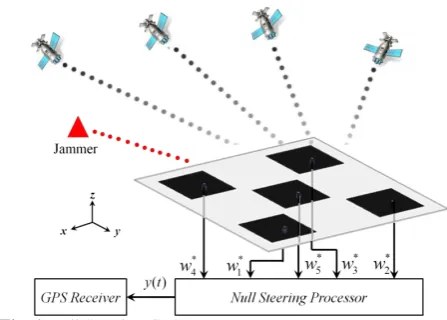
effects have been ignored in the array analysis. The effect of mutual coupling in the GPS anti jamming antenna has been studied in [12-13]. In these papers, first the mutual coupling effect in the antenna array gain, beam width and side lob levels has been discussed, deeply. Then, the error between the output and a locally generated reference signal has been minimized by mean squared error algorithm. A GPS receiver that utilizes an adaptive directional antenna array which points electronically to GPS satellites and suppressing jammers by some prior knowledge about them has been proposed in [14]. The applications of antenna arrays in GNSS interference and multipath environments have been considered in [15] with two stage beamformer without considering the mutual coupling effects. A controlled reception pattern antenna for GPS system has been introduced in [16] which studied the characterization of the code and carrier phase biases introduced by CRPA antenna hardware. A software-based GNSS receiver architecture with a blind null steering beamformer known as the power minimization beamformer has been implemented in [17] by commercial GNSS antennas without considering the mutual coupling effect. Moreover, a five elements anti-jamming antenna array has been designed and fabricated in [18] to mitigate the interference within a compact footprint. Although, this antenna achieve a good polarization, phase and gain diversity within a compact footprint, but the mutual coupling effect has been not studied in the paper. A single feed dual band antenna backed by a hybrid artificial magnetic conductor cavity was introduced for anti jamming applications without discussing about the algorithm. Recently, a robust method has been proposed in [30] to suppress jamming for satellite navigation by reconstructing sample matrix covariance without main lobe nulling. However, the antenna radiation patterns and mutual coupling effect have not been considered. In this paper, a new method is proposed to extract the optimal complex weights for suppression of the jamming signals in a GPS antenna array in presence of mutual coupling. As it depicted in Fig. 1, the optimal element weights are adaptively updated without need to any prior knowledge about the direction of jammer interferences. In more details, the exact active radiation pattern of the array elements are used to achieve the proper complex weight of the antennas. The active radiation pattern of an element is taken with its feeding in the array configuration, where all other array elements are terminated with matched loads. This pattern is generally different from the isolated element pattern, because its adjacent elements radiate some power due to the mutual coupling with the fed element [19]. Moreover, this pattern includes the antenna nearby scatterers such as antenna holders. Using active element pattern in beam forming has been introduced in [20] and developed in [21-23]. Here we use this method for precise design of an anti jam null steering GPS antenna which not considered, previously.
Fig. 1 Null Steering GPS antenna array.
To the best of author knowledge, these specifications have been not considered in the related references all with each other. The presented simulation results clarify the important rule of the mutual effects in the antenna performance.
The outline of this paper is as follow. In Section 2, GPS antenna array geometry is considered that is able to form four nulls in its radiation pattern. The full wave simulation results verify the significant effects of mutual coupling in the antenna radiation patterns. Notice that although we consider a 5-elements GPS array, but the proposed method is universal and can be used in all 2D and 3D array configuration, easily. In the proposed algorithm discussed in Section 3, the array output power is minimized to suppress the effect of jamming sources. The main point in this process is the correct determination of array manifold in the presence of mutual coupling. The simulation results are depicted in Section 4 that clarify the significant effect of mutual coupling in the overall performance of the array. Finally, the antenna performance is evaluated by changing the jammer to signal ratio, SJR and number of jammer sources.
2 Antenna Array Geometry
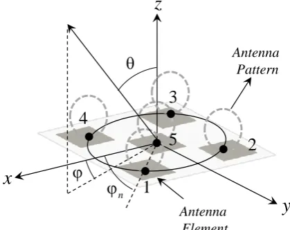
The proposed antenna array geometry is shown in Fig. 2. In this array, four simple linear polarized GPS patch antenna elements are printed uniformly along of a circle with radius of a = 6 cm and the fifth antenna elements is placed at the array center which is the coordinate origin. This element is used as the reference element for the complex weight calculation discussed in Section 3.
All patch antennas are printed on a square RO4003 substrate with length of L = 20 cm, 30 mil thickness and relative permittivity of εr = 3.55. The GPS patch
antenna element is shown in Fig. 2 in more details, also. The side length of this proposed patch antenna is
w = 4.96 mm to achieve a resonance at GPS L1 band, 1.575 GHz. Also, the feed connection point is located on x axis of the antenna structure by h = 0.8 mm
Iranian Journal of Electrical & Electronic Engineering, Vol. 14, No. 2, June 2018 118 Feeding
Point l
l w
w
h x y
a L
L
1 2
3 4
5 45
Feeding Point
l
l w
w
h x y
a
L
L
1 2
3 4
5
45
Fig. 2 Antenna array geometry formed by five identical patch antennas.
movement from the origin, as shown in Fig. 2. Moreover, the substrate length of the stand alone patch antenna element is considered as l = 8 cm. All patch antennas are oriented identically in the array configuration, also.
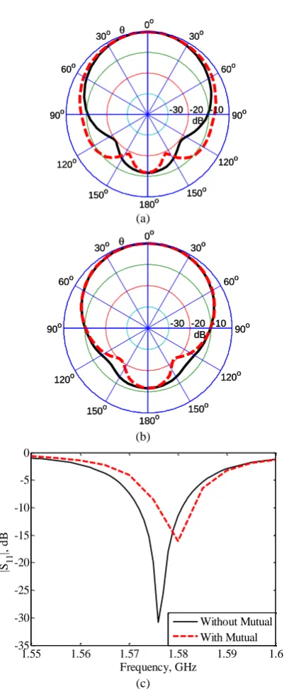
The full wave simulation patterns of the stand alone GPS antenna element and the reference active element patterns in the array (fifth elements) are compared here. Figs. 3(a) and (b) show the normalized antenna radiation patterns comparison at φ = 0, 90˚ planes where the antenna gain is 5.24 and 3.94 dB for the stand alone and reference antennas, respectively. Notice that these antennas are identical and only the mutual coupling changes their attributes. Also, the |S11| responses of these two antennas are plotted in Fig. 3(c). As it shown in this figure, the antenna element has 10 MHz bandwidth (|S11|<-10dB) around the L1 GPS center frequency which covers the bandwidth required for commercial GPS. Theses simulation results clarify the importance of mutual coupling in the antenna specifications.
3 Null Steering Algorithm
In this section, we describe the null steering method. Notice that in this algorithm, there are neither limitations imposed on the array geometry, nor it is necessary to assume identical antenna element radiation patterns. A purely blind null steering beamformer which doesn't need any prior information about the jammer direction of arrival is used to mitigate the jamming signal. Since the GPS signals are well below the noise floor, their contribution in the array covariance matrix
0o
180o
90o 90o
30o
150o 60o
120o 30o
150o 60o
120o
-10 -20 -30
dB 0o
180o
90o 90o
30o
150o 60o
120o 30o
150o 60o
120o
-10 -20 -30
dB
(a)
0o
180o
90o 90o
30o
150o 60o
120o 30o
150o 60o
120o
-10 -20 -30
dB 0o
180o
90o 90o
30o
150o 60o
120o 30o
150o 60o
120o
-10 -20 -30
dB
(b)
1.55 1.56 1.57 1.58 1.59 1.6
-35 -30 -25 -20 -15 -10 -5 0
Frequency, GHz
|S1
1
|,
d
B
Without Mutual With Mutual
(c)
Fig. 3 The designed patch antenna specifications without (black and solid line) and with mutual coupling (red and dashed line) for the fifth element a) radiation pattern at φ = 0° b) radiation pattern at φ = 90° c) |s11|.
can be ignored. Therefore, the array output minimization leads to steer the nulls in the direction of interferences [18, 24]. Notice that this simple method can only mitigate the interferences and the multipath signals cannot be rejected by this approach.
Consider N-elements antenna array where a narrowband beamformer output for this array can be expressed as
Y( )t w X( )H t
(1)
whereX( )t [x t x t1( ), 2( ),...,xN( )]t is the complex
Iranian Journal of Electrical & Electronic Engineering, Vol. 14, No. 2, June 2018 119
vector of array observations versus time and
1 2
w[w w, ,...,wN] is the null steering weights vector. Regarding the notation of this paper, subscript
(.)Hstands for the complex conjugate transpose and the boldface letters are used for matrices.
The array observation vector in a jamming environment can be expressed as
X( ) S ( ) J ( ) N( )
G M
GPS
i j
i j
t
t
t t (2)where SGPS( )
i t is the observation desired signal vector
received from the i-th GPS satellite, J ( )j t is the j-th observation jammer signal and N( )t is a vector specifying the spectral additive white Gaussian noise (AWGN) presented in each antenna channel. The total observed array vector, X( )t can be expressed with more details as
X a , a ,
N
G M
i i i j j j
i j
t s t J t
t
(3)
where a( , i i) is the array manifold vector in ( , i i)
direction, s ti( ) and Jj( )t are the GPS and jammer
signal, respectively.
Assuming zero mean signals with random processes and uncorrelated attribute, the total covariance matrix is defined as the expectation of the outer product of the observed array vector as
22 2 2
R X X a , a ,
a , a , I
R R I .
G
H H
i i i i i i i i
M
H
j j j j j j j n N j
M G
i i j j n N
i j
E t t
(4)where the correlation matrix for GPS and jamming
signals are R a ( , )a ( ,H )
i i i i i i i ,
Rj a (j j, j)a (Hj j, j), respectively. Also, 2
(1, 2,..., )
i G
, 2
(1, 2,..., )
j M
and n2 are the powers
of uncorrelated impinging signals s(k), ij(k), and n(t), respectively. Moreover, INis NN identity matrix. Since the GPS signals prior to dispreading/correlation are below the noise floor, the GPS signal power i2 is
very week. In other words, the total covariance matrix, R is mainly related to the jammer signals and noise. Therefore, the total output power should be minimized by proper complex weight selections to encounter with the jamming signal powers. Also, to avoid the trivial solution (null weight vector), the problem should be
modified with a proper constraint. This constraint can be defined so that only one element (e.g. the reference one) is used in the absence of jammer signals as
1
w cH 1, c[0, 0 , ..., 0, 1]N. (5)
Notice that that other constrains which need the prior knowledge about the GPS direction of arrival can be used, also to improve the GPS signal reception which leads to complexity and cost enhancement.
In other hand, the total array output power can be written as
H H
H H H
Y( )Y ( ) w X( ).X( ) w
w X( ).X( ) w=w Rw.
H
P E t t E t t
E t t
(6)
Therefore, this power minimization problem can be formulated as [25-28]
min wH w, w cH 1.
out
P R subject to (7)
The solution of this minimization problem can be found by using a Lagrange multiplier method leads to
,
wH w
w c 1H
L w R (8)
where λ is the Lagrange multiplier and ( , )L w is the cost function. The solution of this quadratic function can be calculated by [18, 24]
1
H 1
R c w
c R c
(9)
Now, the main problem is R calculation which is related to the array manifold vectors in the jammer and desired GPS signal directions, a( , ) as expressed in (4). Here we define two different cases, ideal and real, to achieve the array manifold vectors in different directions, ( , ) .
3.1 Ideal Case Without Mutual Coupling Effect
The first case where named the ideal case, considers the array antenna elements as isotropic sources without mutual coupling effects from the adjacent antenna elements. Therefore the array manifold for this case can be calculated as
1
2
1
a , exp sin cos ,
sin cos ,...,
cos sin N , 0 .
jka jka
jka j
(10)
where the n is the angular location of each antenna as
shown in Fig. 4. Since the last element, N, is considered in the origin as a reference elements, it's received signal is not related to the angle of arrival rather than the other elements. Therefore the last matrix entry is set zero
Iranian Journal of Electrical & Electronic Engineering, Vol. 14, No. 2, June 2018 120
in (10).
3.2 Real Case With Mutual Coupling Effect
Here we focus on the real case with the mutual coupling effects between the array elements. For this purpose, the active radiation pattern of the antenna elements are extracted from the HFSS full wave simulation software as
1 2E , , ,..., N
r rE rE rE (11)
where
,
,
ˆ
,
ˆi i i
rE rE rE (12)
It is clear that the radiation patterns of the array antenna elements are different due to the mutual effects of the other array elements and scatterer nearby the antenna such as radome, feed line and antenna holders. Now, the array covariance matrix can be expressed as [21]
* 1
R E( , ).[ E( , )]
2 c
r r
Z
(13)
Here (.)*
denotes the complex conjugate, “.” is the scalar product and Zc is the characteristic impedance of the transmission medium. As it mentioned in the introduction, the active element pattern of an antenna in the array structure is obtained by exciting the antenna and terminating the other antenna elements by a match load. The electrical field radiation pattern identified as
( , )
rE in the abovementioned relations is the electric field radiated field, which is multiplied by the radial distance. In more details, since the r dependence is inherent characteristic of a spherical TEM wave and a key feature of far fields, the distance dependence is removed by this multiplication for more simplifications in the relations.
4 Simulation Results 4.1 Mutual Effects
As it depicted in Fig. 3, the antenna patterns are changed significantly due to the mutual coupling effects. Here we aim to evaluate the effect of mutual coupling in the null steering process. For this purpose, we consider the simple 5-elemnts GPS array designed in Section 2. The jammer is assumed to be located at
45
j
and j 45 with jammer to signal ratio (JSR) of 30 dB. Notice that since the GPS signal is below the noise floor, the JSR can be considered as the jammer to noise ratio, also. Moreover, we consider the white Gaussian noise with 2n 0.001 in the simulations.
The complex weight vector of the proposed null steering are calculated for two ideal and real cases
discussed in Section 3. While the antenna radiation patterns are considered as isotropic in the ideal case, they are extracted in the real case (with mutual) from HFSS software in 5 degree steps in both θ and φ directions. In more details, the electrical farfield vectors of each antenna element which includes Ei( , ) and
( , )
i
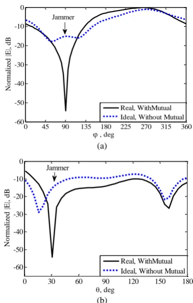
E components are computed by the HFSS to use in (13). It should be mentioned that the HFSS software achieves the electric radiated farfield multiplied by the radial distance, r which is the one needed in the relations provided in the previous section. The required complex weight vectors are calculated by using (8) for these two cases. The results of using these two complex weight vectors are depicted in φ-plane with θj = 45° (Fig. 5(a)) and θ-plane with φj= 45°
(Fig. 5(b)). It can be seen clearly that mutual coupling affects the antenna performance, significantly. In the real case where the mutual couplings are considered, the jammer signal is encountered with more than 50 dB null depth, while it is low in the ideal case and maybe not acceptable. These results clarify the importance of the mutual coupling in extraction of the complex weight vector.
4.2 Multi Jammers
After showing the importance of the mutual coupling effect in the proposed method, we aim to investigate the method ability to deal with multi jammer sources. As it is well know, an array with N elements can rejects N-1 jammer sources. Therefore we evaluate the method with 2, 3 and 4 jammer sources which have the same JSR as 30 dB. The jammer sources locations in these three scenarios are tabulated in Table 1 and the corresponding simulation results are shown in Fig. 6. It can be seen that the proposed method can create proper null in the direction of jammer sources to reject their power. Moreover, it can be seen that the null depth is highly related with the number of jammer sources. In other words, the results show that although the null depth is
z
y
x
Antenna Pattern
5
2
3
4
1
Antenna Element n
Fig. 4 Antenna array with ideal (point source) and real radiation pattern.
Iranian Journal of Electrical & Electronic Engineering, Vol. 14, No. 2, June 2018 121
good enough in all scenarios, but the null depth in the 2-jammer source scenarios is much higher than the 3 and 4-jammer source. To achieve more null depth with constant jammer sources, we can increase the number of array elements, also.
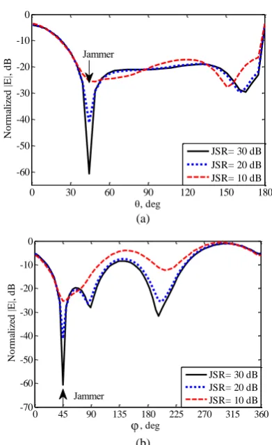
4.3 Jammer to Signal Effects
Since the proposed method works based on the array power minimization, it is expected that JSR enhancement can help more the algorithm to recognize the jammer signals from the noise. To show this fact, we consider one jammer source in j 45 and j 45
with three different JSR as 30, 20 and 10 dB. The simulation results are shown in φ-plane for θj= 45° (Fig. 7(a)) and θ-plane for φj = 45° (Fig. 7(b)). As it can
be seen, the null depth is related highly to the JSR. For example, we have about 60 dB null depth for JSR = 30 dB, while it is about 40 dB for JSR = 20 and only about 25 dB for JSR = 10 dB.
5 Conclusion
An anti jamming GPS antenna was designed in this paper. The designed antenna array was formed by five microstrip patch antenna in planar array geometry. The null steering method was performed by using the exact
0 45 90 135 180 225 270 315 360
-60 -50 -40 -30 -20 -10 0
, deg
N
o
rm
al
iz
ed
|E
|,
d
B
Real, WithMutual Ideal, Without Mutual Jammer
(a)
0 30 60 90 120 150 180
-60 -50 -40 -30 -20 -10 0
, deg
N
o
rm
al
iz
ed
|
E
|,
d
B
Real, WithMutual Ideal, Without Mutual
Jammer
(b)
Fig. 5 GPS Antenna array with point sources and real radiation patterns for SJR=30 dB, SNR=-20 dB and σ = 0.001. The jammer is placed at φj = 90° and θj = 30°. a) φ plane with
θj = 30° b) θ-plane with φj = 90°.
active element patterns of the array antenna. These patterns include the mutual coupling effect and the antenna nearby scatterer such as holder which increase the antenna performance to deal with the jammer sources which was not considered in the literature based on the author knowledge. Moreover, the proposed method can be easily used in conformal array structures due to using active antenna pattern in the method. The simulation results clarified the antenna ability to reject the jammer sources effects.
Table 1 The Jammer Source Locations in Three Different Scenarios.
Jammer Sources Scenarios
Jammer Source Locations
j, j
a) 2- Jammer (20,0),(20,300)
b) 3- Jammer (20,0),(20,300),(60,215)
c) 4- Jammer (20 ,0 ),(30 ,90 ),(60 ,215),(20 ,300 )
, deg
,
d
e
g
0 45 90 135 180 225 270 315 360 0
30 60 90 120 150 180
-60 -40 -20 0
-75dB -66dB
(a)
, deg
,
d
eg
0 45 90 135 180 225 270 315 360
0 30 60 90 120 150 180
-60 -40 -20 0
-62dB
-31dB -29 dB
(b)
, deg
,
d
eg
0 45 90 135 180 225 270 315 360
0 30 60 90 120 150 180
-30 -25 -20 -15 -10 -5 0
-13dB -15 dB
-28dB
-23dB
(c)
Fig. 6 Array patterns after null steering with SJR = 50dB for different jammer locations reported in Table 1. a) 2- jammers b) 3- jammers c) 4-jammers.
Iranian Journal of Electrical & Electronic Engineering, Vol. 14, No. 2, June 2018 122
0 30 60 90 120 150 180
-60 -50 -40 -30 -20 -10 0
, deg
N
o
rm
al
iz
ed
|
E
|,
d
B
JSR= 30 dB JSR= 20 dB JSR= 10 dB
Jammer
(a)
0 45 90 135 180 225 270 315 360
-70 -60 -50 -40 -30 -20 -10 0
, deg
N
o
rm
al
iz
ed
|
E
|,
d
B
JSR= 30 dB JSR= 20 dB JSR= 10 dB Jammer
(b)
Fig. 7 GPS Antenna with different signal to jammer ratio for SNR = -20 dB and σ = 0.001. The jammer is placed at φj = 45°
and θj = 45°. a) φ plane with θj = 45° b) θ plane with φj = 45°
References
[1] Z. Fu, A. Hornbostel, J. Hammesfahr and A. Konovaltsev, “Suppression of multipath and jamming signals by digital beamforming for GPS/Galileo applications,” GPS Solutions, Vol. 6, No. 4, pp. 257–264, 2003.
[2] M. Cuntz, A. Konovaltsev, A. Dreher and M. Meurer, “Jamming and spoofing in GPS/GNSS based applications and services threats and countermeasures,” Communications in Computer and Information Science, Vol. 318, pp 196–199, 2012.
[3] J. R. Lambert, A. Z. Tempe, C. A. Balanis and D. DeCarlo, “Spherical cap adaptive antennas for GPS antennas and propagation,” IEEE Transactions on Antennas and Propagation, Vol. 57, No. 2, pp. 406–413, 2009.
[4] M. M. Casabona and M. W. Rosen, “Discussion of GPS anti-jam technology,” GPS solutions, Vol. 2, No. 3, pp.18–23, 1999.
[5] V. Tree and L. Harry, “Detection, estimation and modulation theory,” Massachussets institute of technology, Jhon Wiley and Sons, 1968.
[6] R. T. Compton Jr, “The power-inversion adaptive
array: Concept and performance,” IEEE
Transactions on Aerospace and Electronic Systems, Vol. 6, pp. 803–814, 1979.
[7] M. Trinkle and W. C Cheuk, “Null-steering GPS dual-polarised antenna arrays,” in The 6th
International Symposium on Satellite Navigation Technology Including Mobile Positioning & Location Services Melbourne, Australia, pp. 22–25, 2003.
[8] D. S. De Lorenzo, J. Gautier, J. Rife, P. Enge and D. Akos, “Adaptive array processing for GPS interference rejection,” in Proceedings of the 18th International Technical Meeting of the Satellite Division of the Institute of Navigation, pp. 618–627, 2005.
[9] W. Kunysz, “Advanced pinwheelä compact controlled reception pattern antenna (AP-CRPA)
designed for interference and multipath
mitigation,” Proceedings of the ION GPS, pp. 2030– 2036, 2001.
[10] D. Reynolds, A. Brown and A. Reynolds, “Miniaturized GPS antenna array technology and predicted anti-jam performance,” Proceedings of the 12th International Technical meeting of the Satellite
Division of the Institute of Navigation, GPS-99, Nashville, pp. 777–785, 1999.
[11] D. Williams, S. Clark, J. Cook, P. Corcoran and S. Spaulding, “Four-element adaptive array evaluation for united states navy airborne applications,” in Proceedings of the 13th
International Technical Meeting of the Satellite Division of The Institute of Navigation, pp. 2523– 2532, 2000.
[12] K. A. Griffith and I. J. Gupta, “Effect of mutual coupling on the performance of GPS AJ antennas. Navigation,” Navigation, Vol. 56, No. 3, pp. 161–173, 2009.
[13] A. S. C. Svendsen and I. J. Gupta, “The effect of mutual coupling on the nulling performance of
adaptive antennas,” IEEE Antennas and
Propagation Magazine, Vol. 54, No. 3, pp. 17–38, 2012.
[14] D. De Lorenzo, Navigation Accuracy and Interference Rejection for GPS Adaptive Antenna Arrays, Stanford University, 2007.
[15] S. Daneshmand, GNSS Interference Mitigation Using Antenna Array Processing, Doctoral dissertation, University of Calgary, 2013.
[16] U. S. Kim, Mitigation of Signal Biases Introduced by Controlled Reception Pattern Antennas in a High Integrity Carrier Phase Differential GPS System, Diss. Stanford University, 2007.
Iranian Journal of Electrical & Electronic Engineering, Vol. 14, No. 2, June 2018 123
[17] J. Arribas, P. Closas and C. Fernandez-Prades, “Interference mitigation in GNSS receivers by array
signal processing: A software radio
approach,” in Sensor Array and Multichannel Signal Processing Workshop (SAM), 2014 IEEE 8th, pp.
121–124, 2014.
[18] W. Alshrafi, U. Engel and T. Bertuch, “Compact controlled reception pattern antenna for interference mitigation tasks of global navigation satellite system receivers,” IET Microwaves, Antennas & Propagation, Vol. 9, No. 6, pp. 593–601, 2014.
[19] D. M. Pozar, “The active element pattern,” IEEE Transactions on Antennas and Propagation, Vol. 42, No. 8, pp. 1176-1178, 1994.
[20] H. Rogier and D. D. Zutter, “Beamforming strategies for compact arrays in mobile terminals using the exact active element pattern method,”
Microwave and Optical Technology Letters, Vol. 35, No. 3, pp. 201–203, 2002.
[21] P. Demarcke, H. Rogier, R. Goossens and P. D. Jaeger, “Beamforming in the presence of mutual coupling based on constrained particle swarm optimization,” IEEE Transactions on Antennas and Propagation, Vol. 57, No. 6, pp. 1655–1666, 2009.
[22] H. Rogier and D. D. Zutter, “Prediction of noise and interference cancellation with a moving compact receiver array in an indoor environment,” IEEE transactions on vehicular technology, Vol. 54, No. 1, pp. 191-197, 2005.
[23] R. Goossens, I. Bogaert and H. Rogier, “Phase-mode processing for spherical antenna arrays with a finite number of antenna elements and including mutual coupling,” IEEE Transactions on Antennas and Propagation, Vol. 57, No. 12, pp. 3783–3790, 2009.
[24] F. Le Chevalier, D. Lesselier and R. Staraj, “Anti jamming for satellite navigation,” Non-standard Antennas, pp. 343–383.
[25] S. A. Vorobyov, “Principles of minimum variance robust adaptive beamforming design,” Signal Processing, Vol. 93, No. 12, pp. 3264–3277, 2013.
[26] B. G. Frank, Smart Antennas for Wireless Communications with MATLAB, McGraw-Hill. New York, 2005.
[27] J. Litva and T. K. Lo, Digital Beam Forming in Wireless Communications, Artech house, 1996.
[28] Van Trees, Harry L. Detection, “Estimation, and modulation theory, optimum array processing,” John Wiley & Sons, 2004.
[29] S. X. Ta and I. Park, “A single-feed dual-band antenna for an anti-jam GPS array,” in International Workshop on Antenna Technology (iWAT), pp. 327– 329, 2015.
[30] Y. Gong L. Wang, R. Yao, and Z. Zhang, “A robust method to suppress jamming for GNSS array antenna based on reconstruction of sample covariance matrix,” International Journal of Antennas and Propagation, pp.1–12, 2017.
H. Sedighy was born in Qaen, South Khorasan, Iran in 1983. He received B.Sc., M.Sc. and Ph.D. degrees in Electrical Engineering from Iran University of Science and Technology (IUST) in 2006, 2008 and 2013 respectively. From December 2011 to July 2012, he was with the University of California, Irvine as a Visiting Scholar. He is currently an Assistant Professor in School of New Technologies of IUST.