Iranian Journal of Electrical & Electronic Engineering, Vol. 14, No. 3, September 2018 289
Optimal DG Allocation and Thyristor-FCL Controlled
Impedance Sizing for Smart Distribution Systems Using
Genetic Algorithm
A. S. Hoshyarzadeh*, B. Zaker*, A. A. Khodadoost Arani* and G. B. Gharehpetian*(C.A.)
Abstract: Recently, smart grids have been considered as one of the vital elements in upgrading current power systems to a system with more reliability and efficiency. Distributed generation is necessary for most of these new networks. Indeed, in all cases that DGs are used in distribution systems, protection coordination failures may occur in multiple configurations of smart grids using DGs. In different configurations, there are various fault currents that can lead to protection failure. In this study, an optimal DG locating and Thyristor-Controlled Impedance (TCI) sizing of resistive, inductive, and capacitive type is proposed for distribution systems to prevent considerable changes in fault currents due to different modes of the smart grid. This problem is nonlinear constrained programming (NLP) and the genetic algorithm is utilized for the optimization. This optimization is applied to the IEEE 33-bus and IEEE 69-bus standard distribution systems. Optimum DG location and TCI sizing has carried out in steady fault currents in the grid-connected mode of these practical networks. Simulation results verify that the proposed method is effective for minimizing the protection coordination failure in such distribution networks.
Keywords: Distributed Generation, Genetic Algorithm, Protection Coordination, Smart Grid.
1 Introduction1
mart grids are comprehensive approach for enhancing the quality and reliability of different sections of electrical power system including generation, transmission, distribution, and consumption. A combination of technologies has transformed the traditional power system to modernized smart grid. By developing the power supply, consumers become more satisfied. Proper management of resources and new processes will increase the efficiency of power networks. The smart grid offers more accessibility and better response to a variety of demands. Other major advantages of the smart grid are adjustment to different
Iranian Journal of Electrical & Electronic Engineering, 2018. Paper first received 27 June 2017 and accepted 02 February 2018. * The authors are with the Department of Electrical Engineering, Amirkabir University of Techology,Tehran, Iran.
E-mails: [email protected], [email protected],
[email protected] and [email protected]. Corresponding Author: G. B. Gharehpetian.
situations by its fashionable design [1,2]. Nevertheless, providing a new system with coordinated protection devices has opened a new stage in studying the smart grid protection.
One of the fundamental units that are necessary in the smart grid is distributed generation. There are many advantages in using DGs such as power quality and voltage profile improvement. In addition, when power rating is variable in a distribution system, utilizing DG would become important. DG offers more opportunities for using renewable energies like photovoltaic (PV) systems and wind turbines. Although DGs are key elements in the smart grid and future distribution systems, DGs change some indices of the previous network such the fault’s current levels in different operation modes. Thus protection coordination problems may occur due to these fluctuations in fault currents. The amount of these changes depends on a few factors, namely, network configuration, DGs’ locations, and FCL size [1-6].
Diversity in the fault current’s amplitude or current’s directions can adversely affect fuses and relays and
S
Iranian Journal of Electrical & Electronic Engineering, Vol. 14, No. 3, September 2018 290 seriously damage them in long periods of time [5,6]. In
[7], the authors deal with improving the reliability, by means of calculating DG capacity and other reliability parameters. In [8] an approach in which FCLs were connected in series to DGs has been introduced to prevent protection coordination problems in a loop distribution network with directional over current relays.
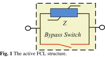
Thanks to power electronics advancements in recent years, new devices for power system problems have been introduced. Fault current limiter (FCL) is a semiconductor device that can restrain fault currents in case of disturbance. Fault current limiters can be either passive or active. The passive types of FCLs constantly remain in the power system circuit; hence during normal operation the extra impedance results in a voltage drop in the power system. Conversely, the active FCLs have more flexibility; providing low impedance in normal configuration and high impedance in fault situations. Active FCLs have become more reliable than the passive types. Most pioneering FCL technologies are active types. Once the active FCL is installed in the network, it would be possible to increase or decrease the impedance under appropriate circumstances [9]. Fig. 1 presents the structure of active FCL. In [10] and [11], by using one specific category of active FCL which is Thyristor-Controlled Impedance (TCI), the protection of the distribution system has been improved.
The DG’s type should be considered in analyzing various configurations of such power systems. DGs can be divided into two subcategories; the first category is inverter-based DGs. In this type the limitation of the fault current increases protection coordination failure in smart grids with islanded capability. In this case fault currents are much lower than the rating of traditional protection fuses or relays. Different relays and protection devices have been adjusted for this problem [12-15]. In [12], to solve this problem, digital relays have been proposed. In [14-15], admittance relays, and impedance relays have been utilized to avoid mismatch between fault currents in operating modes of the smart grid.
In contrast to inverter-based DGs, synchronous-based types have much higher fault currents in the smart grid modes, thereby application of the traditional protection system is possible. The matter is that new fault currents are not the same as the faults’ levels in the normal mode. This can cause the system to experience protection coordination failure, but it is expected from the smart grid to work under different modes [1-7]. In [16] a cost effective function has been proposed to prevent protection coordination failure. A method using particle swarm optimization (PSO) has been presented in [17] to find the optimum FCL size which assists in avoiding changes in fault currents during different modes. However the location of DG was not optimized
Fig. 1 The active FCL structure.
to attain the optimum solution. It has been stated in [18,19] that protection coordination is crucial for islanded operation and PSCAD has been used to shun protection failure in a practical network. To overcome problems of using over-current relays, the application of suitable FCL’s type and size has been proposed in [20]. The significance of FCL for keeping fault currents constant and securing the power system from possible damage was explained in [21].
In this paper, the Genetic algorithm (GA) is implemented to obtain optimum places of DGs and FCL’s size in the power system. GA and other algorithms have been used for optimizing numerous engineering problems [22,23,26,29]. The network has been considered with no islanded capability and the main objective of the fitness function is reducing the inconsistencies between bus impedance matrixes under two configurations. It is assumed that DGs are synchronous-based type and FCLs are TCI type (can be a combination of resistive, passive or active) connected in series with DGs. The main difference between this problem formulation and later methods is taking into account both DGs’ places and FCLs’ sizes in order to achieve optimum fitness value from the perspective of maintaining fault currents in different configurations. Previous studies have invariably assumed that DGs have been installed in some random buses and they have just attempted to find the optimum size of FCLs. However, in the majority of distribution systems, protection coordination occurs exclusively in special buses. Hence, if regulating the protection devices for different relays and fuses, is the ultimate goal of optimization, the optimization should be run for both locating and sizing. In fact, reliable protection coordination is possible in optimum places, which are dependent on the system’s topology. In this study, the optimum response is directly related to the location of DGs as well as the size of FCLs. Thereby, the essentiality of selecting correct buses to connect DGs is completely determined for two sample distribution systems.
Paper contributions are summarized below:
1. As fault current levels of the DG-connected mode and non DG-connected mode of distribution systems greatly differ from each other, network operators encounter vast protection coordination problem. In order to equalize these fault currents, a GA optimization-based methodology is presented to acquire optimum DGs connection buses and optimum active FCL sizes (in series with DGs).
Iranian Journal of Electrical & Electronic Engineering, Vol. 14, No. 3, September 2018 291 The simulation result shows the great importance of
recognizing correct buses for DGs connection in such networks. It is shown that the fault currents convergence (in two modes) is possible only in specific connection points and FCL sizes. Network operators can avoid protection coordination problems by employing this methodology prior to DG installation.
2. Although both GA and PSO are capable of solving the problem, GA shows slightly better convergence in implementation compared to the proposed combinatorial binary constrained problem. However, PSO has faster solvation ability. While speed is not a concern in this kind of problems, GA has relatively more acceptable performance. This paper is organized as follows. In Section 2, the problem formulation and the method in which the genetic algorithm is implemented to two IEEE standard systems are discussed. Section 3 illustrates the simulation results and convergence diagrams for case studies, and Section 4 constitutes the conclusion of the paper.
2 Problem Formulation
Distributed generation is one of the necessary aspects of new distribution power systems and smart grids that are called DG technology. Moreover, DG is key ingredient for providing consumers with high quality and reliable power. However, using DGs in the distribution system alters power system’s short circuit fault currents. To find a solution for this issue, the genetic optimization algorithm which can determine the best place for DGs in the network and the optimum size of FCLs is conducted to prevent distinct fault currents and protection coordination failure. This problem is solved for IEEE 33 and 69-bus standard distribution systems. Solely, two operations for these networks are regarded to be available. Hence, there are two different configurations for these networks:
Configuration A: grid connected without DG connection,
Configuration B: grid connected with DG connection.
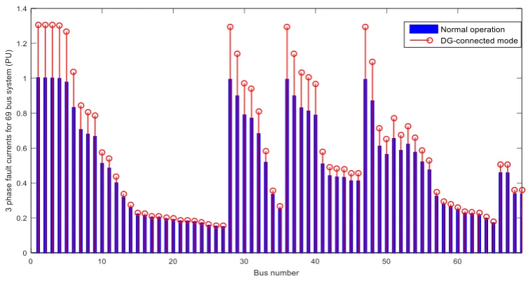
Configuration A is a normal configuration where there is no change in the basic currents, but configuration B, called as “DG-connected mode”, is where DGs are connected to the network. In the presence of DGs in the system, there are some differences in power flow paths compared to the normal mode of the network; therefore fault current’s levels increase in some buses. The increment in short circuit currents in 3 DG operation mode can be observed for IEEE 33 and 69-bus networks in Fig. 2 and Fig. 3, respectively (DGs are connected to buses 2, 3, and 4 in both 33 and 69-bus systems, and there is no FCL in the distribution networks).
As it can obviously be seen from Fig. 2 and Fig. 3, the difference between fault currents is considerable and
this highlights the importance of installing FCLs in the distribution systems. The change in the fault currents in different configurations is minimized by means of minimizing the change in the impedance matrix of these configurations. The question here is to find the best buses for connecting DGs and optimum FCL sizes for maintaining constant fault currents as much as possible. It is assumed that FCLs are always in series with DGs in any buses that DGs are connected to. For both IEEE networks the total demand is about 4.5 MVA(4.4 for 33 bus and 4.6 for 69 bus) and this power is provided by three 1.5 MVA DGs or two 2 MVA DGs. Taking into account the DGs cost, it is not rational for these distribution systems to divide the power between more than three DGs. Basically, the lower the DG generation, the higher the cost that should be paid per each kW. This extra cost grows dramatically when DGs with 1 MVA or less capacity are being used [24]. As satisfying results are reachable by 2 or 3 DG operations, installing more than 3 DGs only bring an unnecessary extra cost for network operators.
The impedance matrix for configuration A is the normal impedance matrix of the network. On the other hand, in configuration B, DG’s impedances, and DG’s places which are constituent components of the distribution system in the second mode make some changes to the impedance matrix and thus:
( , , , ) 1:
B k k k s
Z F tci I p tci k n (1)
where ZB represents the impedance matrix of the
configuration B and n is the number of DGs in the system, and k represents the specific DG between n
DGs. Parameters, tcik, lk, and pk refer to TCI impedance
in series with the DG number k, the location of DG number k, and power generated by DG number k
respectively. tcis is for TCI source impedance at the
utility. The FCL source is always connected to bus number 1, because the role of this bus in maintaining fault currents is critical. Any FCL consists of real and imaginary parts, whereby for either TCIs in series with DGs or the TCI source, it can be represented as follows:
1:
k s
tci k k
tci s s
Z R jX k n
Z R jX
(2)
where Rk and Rs stand for resistive part, Xk and Xs are for
reactance. It is assumed that the reactance can be positive or negative (inductive or capacitive). The impedance matrix of a network has important data of the network. The ith diagonal element (z
ii) of this matrix
represent of Thevenin impedance from this bus. The fault current of this bus (If _Bus#i) can be calculated as follows:
_ #
1 f Bus i
ii
I
z
(3)
Iranian Journal of Electrical & Electronic Engineering, Vol. 14, No. 3, September 2018 292 Fig. 2 Comparison between three phase fault currents in configurations A and B for 33-bus system.
Fig. 3 Comparison between three phase fault currents in configurations A and B for 69-bus system.
In addition, the zij is used for the fault current between
bus i and bus j. Therefore, if the impedance matrix of two configurations is equal, the differences between fault currents in two configurations are minimized. As mentioned above, the fitness function is the difference between two impedance matrices, so the objective function can be expressed as follows [17]:
, ,
1 1 i j i j
n n
A B
i j
Z Z
(4)As much as (4) is closer to zero the inconsistencies in the two matrices is smaller. In short, by the assuming the voltage level of 1 p.u in all buses, fault current levels are only dependent on impedance matrices. Therefore, fault current levels can be maintained by minimizing the difference in two matrices. In (1), it can be seen that the impedance matrix of the second mode is a function of DG location and FCL size. Hence, the fitness function consequently becomes a function of these terms. Equation (4) expressed fitness function for GA. By running the optimization for the described systems, the best locations for DG and FCL sizes can be acquired. The number of variables for GA depends on the number of DGs that are applied in the power system.
Any FCL in series with DG requires two variables for real and imaginary parts (resistive and passive or active). Furthermore, each DG needs one integer variable for the location. There are always two variables for the FCL source. Therefore, the number of variables in the power system with n DGs is as follows:
Number of variables needed for GA3n2 (5)
It is obvious from the fitness function that the problem is nonlinear programming (NLP). The range of FCL sizes is also restricted and DG locations have integer constraints. Bus numbers in which DGs can be installed are integer variables and limited according to the number of the power system buses. Thus, the problem is a nonlinear, integer and linear constrained programing. For constraints it can be expressed as follows:
max
0
k k
R R
(6)
mink k maxk
X X X (7)
max
0
s s
R R
(8)
mins s maxs
X X X (9)
Equations (6) and (7) refer to limitations for TCIs in
Iranian Journal of Electrical & Electronic Engineering, Vol. 14, No. 3, September 2018 293 series with DGs, while (8) and (9) indicate the
boundaries of TCI in the PCC. The integer constraint is for clarifying the limitation of variables which show the DGs’ location and thus m can be defined as:
2ms m (9)
where m is the variable with integer constraints and s is the total number of buses in the power system. The best locations can be found by optimum point for m. According to previous equations the boundaries for 33 and 69-bus distribution systems are given in Table 1. The GA data are given in Table 2.
In the proposed approach, the stability in the impedance matrix is the criteria for maintaining the fault current levels. These fault currents which are in proportion with the matrix are three phase fault currents. Three phase fault currents are the highest fault values in such distribution networks. Hence, single phase and double phase fault currents are also covered by this methodology.
3 Simulation Results
The simulations are carried out for standard IEEE 33-bus and 69-33-bus distribution systems. Many optimization problems have been applied to these distribution systems to prove their adoption to various distribution networks [25,28]. The result leads to the best DG places and optimum sizes of FCLs for these practical distribution networks. Optimizing is utilized for both 33 and 69-bus distribution systems with two and three DGs, and also with FCL source in the PCC. This approach assists power system’s operators in finding the best state for DG place and FCL size for various distribution networks. Hence, protection coordination failure would not occur even with traditional fuses and relays. Indeed, the system can continue working with former protection devices, which is a tremendous enhancement from an economical point of view. First, the 69-bus distribution system is analyzed completely
Table 1 Constraints for GA optimization variables in 33 and 69-bus systems.
33-Bus System
Variable Minimum Maximum
Xk & Xs -10 10
Rk & Rs 0 10
m 2 33
69-Bus System
Xk & Xs -10 10
Rk & Rs 0 10
m 2 69
Table 2 GA data in implementation to 33 and 69-bus systems.
Individuals 6000
mutation 2500
crossover 2000
survivors 1000
Max iteration 200
because of its greater complexity and then the 33-bus distribution system is assessed briefly.
3.1 69-Bus Distribution System
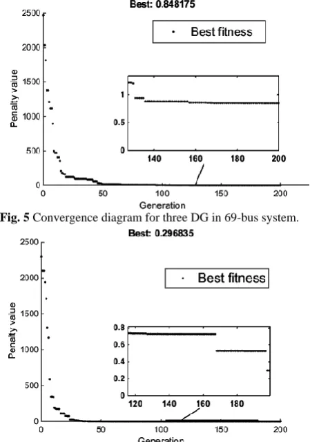
The diagram of the 69-bus IEEE standard distribution system is given in Fig. 4. The GA and PSO algorithms are implemented to the 69-bus system and best locations for three DGs and two DGs operations are given in Table 3. The PSO and GA convergence diagrams are presented in Fig. 5 and Fig. 6.
Fig. 4 Single line diagram of IEEE 69-bus distribution system.
Fig. 5 Convergence diagram for three DG in 69-bus system.
Fig. 6 Convergence diagram for two DG mode in 69-bus system.
Iranian Journal of Electrical & Electronic Engineering, Vol. 14, No. 3, September 2018 294 Table 3 GA and PSO results in three DG and two DG operation for 69-bus distribution system.
GA results for three DG operation GA results for two DG operation
DG
Number Location FCL Size FCL Source Best Fitness
DG
Number Location FCL Size
FCL Source
Best Fitness DG 1
(1.5 MVA) 28 3.48+8.972j
0.048+
0.275i 0.8481
DG 1
(2MVA) 2 7.353+9.313j
0.011+
0.138i 0.29683 DG 2
(1.5 MVA) 36 2.91+4.549j
DG 2
(2 MVA) 3 1.546+7.186j
DG 3
(1.5 MVA) 47 1.23+0.386j
PSO results for three DG operation PSO results for two DG operation
DG
Number Location
FCL
Size FCL Source Best Fitness
DG
Number Location FCL Size
FCL Source
Best Fitness DG 1
(1.5 MW) 4 4.0267+0.29311j
0.01046+
0.30675i 1.0615
DG 1
(2 MW) 2 1.8318+4.5763j
0.029363+
0.19119i 5.4484 DG 2
(1.5 MW) 28 2.2563+2.0257j
DG 2
(2 MW) 5 2.7356+5.1776j DG 3
(1.5 MW) 36 3.3053+6.2336j
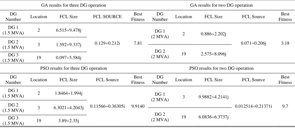
Table 4 GA and PSO results in two DG and three DG operation for 33-bus distribution system.
GA results for three DG operation GA results for two DG operation
DG
Number Location FCL Size FCL SOURCE
Best Fitness
DG
Number Location FCL Size FCL Source
Best Fitness
DG 1
(1.5 MVA) 2 6.515+9.478j
0.129+0.212i 7.81
DG 1
(2 MVA) 2 0.886+2.202j
0.071+0.206j 3.18 DG 2
(1.5 MVA) 3 1.592+9.337j
DG 2
(2 MVA) 19 2.575+8.096j DG 3
(1.5 MVA) 19 0.097+5.584j
PSO results for three DG operation PSO results for two DG operation
DG
Number Location FCL Size FCL Source
Best Fitness
DG
Number Location FCL Size FCL Source
Best Fitness
DG 1
(1.5 MVA) 2 1.8464+1.994j
0.11566+0.36305i 9.9140
DG 1
(2 MVA) 3 9.9882+4.2141j
0.012514+0.21371i 9.7 DG 2
(1.5 MVA) 3 6.3021+4.2043j
DG 2
(2 MVA) 19 6.0836+6.3737j DG 3
(1.5 MVA) 19 3.89+2.35j
3.2 33-Bus Distribution System
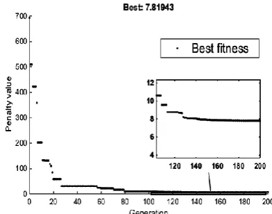
The diagram of the 33-bus IEEE standard distribution system is shown in Fig. 7. The comparison of Fig. 2 propounds that the fault currents’ levels are substantially higher in DG-connected operation. This variation in fault currents in two configurations, especially in buses such as 1, 2, 3, 4, 5, 19, and 23 can certainly result in protection failure. The results of GA and PSO optimization methods for this system are listed in Table 4 for two scenarios (two DG and three DG operation). Convergence diagrams are shown in Fig. 8 and Fig. 9. The data in Table 4 asserts that only the inductive type of FCL is suitable for this distribution network. Again, it is vivid that PSO has relatively lower convergence than GA.
In addition, the optimization is also carried out in the absence of the FCL source. For this case, the best fitness
values are presented in Table 5. Obviously; optimum fitness values are greatly larger than optimal values with the presence of the FCL in the PCC. Hence, optimization is not successful in maintaining fault currents without FCL source. This highlights the critical role of FCL in bus number 1.
Following columnar graph comparisons between fault currents, presented in Fig. 10 and Fig. 11 proves the effectiveness of the proposed optimization
Table 5 GA results without FCL source.
33-bus distribution system 69-bus distribution system
Operation
mode Best fitness
Operation
mode Best fitness
2 DG 107.52 2 DG 427.37
3 DG 144.91 3 DG 563.38
Iranian Journal of Electrical & Electronic Engineering, Vol. 14, No. 3, September 2018 295 framework in maintaining fault currents. Fault currents
of normal operation are the same as before (Fig. 2 and Fig. 3), but in DG-connected mode, DGs are installed in optimum places and optimum FCL sizes are utilized in order to minimize the divergence in fault currents. Fig. 10 and Fig. 11 show that by using this methodology, fault currents are almost the same in 2 modes and there is no protection coordination problem. Employing this methodology results in large monetary saving for network operators. Operators can continue using the traditional protection devices without any protection coordination problem in the distribution systems. Therefore, it is necessary to determine the best locations for DG installation so as to avoid changing protection devices that are prohibitively expensive.
Fig. 7 Single line diagram of IEEE 33-bus distribution.
Fig. 8 Convergence diagram for three DG mode in 33-bus system.
Fig. 9 Convergence diagram for two DG mode in 33-bus system.
Fig. 10 Comparison between three phase fault currents after using optimum DG locations and FCL sizes in 33-bus system.
Fig. 11 Comparison between three phase fault currents after using optimum DG locations and FCL sizes in 69-bus system.
Iranian Journal of Electrical & Electronic Engineering, Vol. 14, No. 3, September 2018 296 4 Conclusion
Connecting DGs to the power system increases the operation modes of the distribution system. In the configuration which is called DG-connected mode, DGs are connected to the grid and fault currents considerably exceed from the normal configuration. This paper introduces a new approach based on optimizing DGs’ location and FCLs’ size, in order to acquire the best results for sustaining the faults’ levels due to various modes of the distribution network. The difference in the impedance matrix of each configuration constitutes the fitness function for genetic algorithm optimization. This problem formulation is implemented for 33 and 69-bus standard IEEE distribution systems. Both 33 and 69-bus cases are optimized with two and three DGs. For each system the optimum positions of DGs and sizes of TCIs which that can maintain the fault currents constant, have been obtained. In either case, the solely inductive type of FCL is appropriate for minimizing the divergence in fault currents. It is also shown that the presence of FCL in the PCC is necessary for attaining acceptable answers for the problem. The significance of locating DGs besides determination of optimum FCLs’ sizes has been proven in this study. As a result, the protection coordination can be obtained in specific DG locations, depending on the topology of the power system.
Appendix
Simulations data are listed in Table 6.
Table 6 Simulation data.
69-bus and 33-bus source and DG system data Utility data MVASC=100 MVA, X/R=6
DG transformer reactance X
+=X- =5%
Y-grounded DG reactance X+=X- =9.67%
Base KV 12.47
Base MVA 100
References
[1] E. M. Lightner and S. E. Widergren, “An orderly transition to a transformed electricity system,” IEEE
Transactions on Smart Grid, Vol. 1, No. 1, pp. 3–
10, Jun. 2010.
[2] A. Molderink, V. Bakker, M. G. C. Bosman, J. L. Hurink, and G. J. M. Smit, “Management and control of domestic smart grid technology,” IEEE
Transactions on Smart Grid, Vol. 1, No. 2, pp. 109–
119, Sep. 2010.
[3] D. S. Popovic and E. E. Boskov, “Advanced fault management as a part of smart grid solution,” in
Procedings IET CIRED Seminar: Smart Grids
Distribution, pp. 1–4, Jun. 2008.
[4] S. M. Brahma and A. A. Girgis, “Development of adaptive protection scheme for distribution systems with high penetration of distributed generation,”
IEEE Transactions on Power Delivery, Vol. 19,
No. 1, pp. 56–63, Jan. 2004.
[5] R. A. Walling, R. Saint, R. C. Dugan, J. Burke, and L. A. Kojovic, “Summary of distributed resources impact on power delivery systems,” IEEE
Transactions on Power Delivery, Vol. 23, No. 3,
pp. 1636–1644, 2008.
[6] N. Nimpitiwan, G. Heydt, R. Ayyanar, and S. Suryanarayanan, “Fault current contribution from synchronous machine and inverter based distributed generators,” IEEE Transactions on Power Delivery, Vol. 22, No. 1, pp. 634–641, Jan. 2007.
[7] S. Chaitusaney and A. Yokoyama, “Prevention of reliability degradation from recloser-fuse miscoordination due to distributed generation,”
IEEE Transactions on Power Delivery, Vol. 23,
No. 4, pp. 2545–2554, 2008.
[8] W. El-Khattam and T. Sidhu, “Restoration of directional overcurrent relay coordination in distributed generation systems utilizing fault current limiters,” IEEE Transactions on Power Delivery, Vol. 23, No. 2, pp. 576–585, Apr. 2008.
[9] M. Noe, M. Steurer, S. Eckroad, and R. Adapa, “Progress on the R&D of fault current limiters for utility applications,” in IEEE Power and Energy Society General Meeting-Conversion and Delivery of Electrical Energy in the 21st Century, pp. 1–4, Jul. 2008.
[10]B. Boribun and T. Kulworawanichpong. “Comparative study on a fault current limiter with thyristor-controlled impedances,” in 13th
International Conference on Harmonics and Quality
of Power, pp. 1–5, 2008.
[11]M. M. A. Salama, H. Temraz, A. Y. Chikhani, and M. A. Bayoumi, “Fault-current limiter with thyristor-controlled impedance,” IEEE Transactions
on Power Delivery, Vol. 8, No. 3, pp. 1518–1528,
Jul. 1993.
[12]E. Sortomme, S. S. Venkata, and J. Mitra, “Microgrid protection using communication-assisted digital relays,” IEEE Transactions on
Power Delivery, Vol 25, No. 4, pp. 2789–2796,
Oct. 2010.
[13]H. Nikkhajoei and R. H. Lasseter, “Microgrid protection,” in IEEE Power Engineering Society
General Meeting, pp. 1–6, Jun. 2007.
Iranian Journal of Electrical & Electronic Engineering, Vol. 14, No. 3, September 2018 297 [14]M. Dewadasa, R. Majumder, A. Ghosh, and
G. Ledwich, “Control and protection of a microgrid with converter interfaced micro sources,” in
International Conference on Power Systems (ICPS),
pp. 1–6, Dec. 2009.
[15]Y. Han, X. Hu, and D. Zhang, “Study of adaptive fault current algorithm for microgrid dominated by inverter based distributed generators,” in 2nd IEEE
International Symposium on Power Electronics for
Distributed Generation Systems (PEDG), pp. 852–
854, Jun. 2010.
[16]S. Shahriari, A. Yazdian, and M. Haghifam, “Fault current limiter allocation and sizing in distribution system in presence of distributed generation,” in
Power & Energy Society General Meeting, pp. 1–6,
2009.
[17]H. H. Zeineldin, E. F. El-Saadany, M. M. Salama, A. H. Kasem Alaboudy, W. L. Woon, “Optimal Sizing of Thyristor-Controlled Impedance for Smart Grids With Multiple Configurations,” IEEE
Transactions on Smart Grid, Vol. 2, No. 3, pp. 528–
537, 2011.
[18]H. J. Laaksonen, “Protection principles for future microgrids,” IEEE Transactions on Power
Electronics, Vol. 25, No. 12, pp. 2910–2918,
Dec. 2010.
[19]N. Amjady, F. Keynia, and H. Zareipour, “Short-term load forecast of microgrids by a new bilevel prediction strategy,” Transactions on Smart Grid, Vol. 1, No. 3, pp. 286–294, Dec. 2010.
[20]A. Agheli, H. A. Abyaneh, R. M. Chabanloo, and H. H. Dezaki, “Reducing the impact of DG in distribution networks protection using fault current limiters,” in 4th International Power Engineering
and Optimization Conference (PEOCO), pp. 298–
303, 2010.
[21]T. A. Tarique, M. A. Zamee, and M. I. Khan, “A new approach for pattern recognition with Neuro-Genetic system using Microbial Neuro-Genetic Algorithm,”
in International Conference on Electrical
Engineering and Information & Communication
Technology (ICEEICT), pp. 1–4, 2014.
[22]G. Cvetkovski, and L. Petkovska, “Genetic algorithm as a tool for multi-objective optimization of permanent magnet disc motor,” Archives of
Electrical Engineering, Vol. 65, No. 2, pp. 285–294,
2016.
[23]V. Tamilselvan and T. Jayabarathi, “Multi objective Flower Pollination Algorithm for solving capacitor placement in radial distribution system using data structure load flow analysis,” Archives of Electrical
Engineering, Vol. 65, No. 2, pp. 203–220, 2016.
[24]D. Pauschert, “Study of equipment prices in the power sector,” ESMAP Technical Paper, Feb. 2009.
[25]S. A. Taher and S. A. Afsari, “Optimal location and sizing of DSTATCOM in distribution systems by immune algorithm,” International Journal of
Electrical Power & Energy Systems, Vol. 60,
pp. 34–44, 2014.
[26]B. Bhattacharyya, S. Rani, R. I. Vais, and I. P. Bharti, “GA based optimal planning of VAR sources using Fast Voltage Stability Index method,” Archives of Electrical Engineering, Vol. 65, No. 4, pp. 789–802, 2016.
[27]P. Yu, B. Venkatesh, A. Yazdani, and B. N. Singh, “Optimal location and sizing of fault current limiters in mesh networks using iterative mixed integer nonlinear programming,” IEEE Transactions on
Power Systems, Vol.31, No. 6, pp. 4776–4783,
2016.
[28]H. Heydari and R. Sharifi, “An optimal design approach for resistive and inductive superconducting fault current limiters via mcdm techniques,” Iranian
Journal of Electrical and Electronic Engineering,
Vol. 7, No. 1, pp. 52–59, 2011.
[29]M. Farshad and J. Sadeh, “Fault locating in high voltage transmission lines based on harmonic components of one-end voltage using random forests,” Iranian Journal of Electrical and
Electronic Engineering, Vol. 9, No. 3, pp. 158–166,
2013.
A. S. Hoshyarzadeh received the B.Sc. (Hon.) in Electrical Engineering from Amirkabir University of Technology, Tehran, Iran, in 2016. He is pursuing a M.Sc. (Hon.) in Electrical Engineering at University of Calgary, Alberta, Canada. He is currently working as a Research Assistant at University of Calgary. His focus is mainly on dynamic load modeling, big data applications in PMU recorded data analysis and stability studies in power systems.
B. Zaker was born in Shiraz, Iran in 1989. He received the B.Sc. degree in Electrical Power Engineering from Shiraz University, Shiraz, Iran, in 2011; the M.Sc. degree in Electrical Power Engineering from Amirkabir University of Technology Tehran, Iran, 2013. He is currently pursuing the Ph.D. degree in Electrical Power Engineering at Amirkabir University of Technology. He has a lot of practical experience in modeling and parameter estimation of power plants in Iran. His research interests include system identification, power system dynamics, distributed generation systems, and microgrids.
Iranian Journal of Electrical & Electronic Engineering, Vol. 14, No. 3, September 2018 298 A. A. KhodadoostArani was born in 1991
in Iran. He received his B.Sc. and M.Sc. degrees from Electrical Engineering Department of Amirkabir University of Technology (AUT), Tehran, Iran, in 2013 and 2015, respectively. His research interests include power electronics, storage systems, power system optimization and operation, FACTS devices, and microgrids.
G. B. Gharehpetian (M’00–SM’08)
received his Ph.D. degrees in Electrical Engineering in 1996 from Tehran University. As a Ph.D. student, he received a scholarship from DAAD (German Academic Exchange Service) from 1993 to 1996, and he was with High Voltage Institute of RWTH Aachen, Aachen, Germany. He has been holding the Assistant Professor position at AUT from 1997 to 2003, the position of Associate Professor from 2004 to 2007 and has been Professor since 2007. His teaching and research interest include smart grid, DGs, monitoring of power transformers, FACTS devices, HVDC systems, and power system transients.