ECE103 Logic Design
and Switching Theory
Text: Digital Design by
Text: Digital Design by
M. Morris Mano, 3
M. Morris Mano, 3
ndndEdition
Edition
Course Content
I. Binary Systems
II. Boolean Algebra and Logic Gates III. Simplification of Boolean Functions IV. Combinational Logic
V. MSI and PLD Components
VI. Synchronous Sequential Logic
VII. Registers, Counters, and the Memory Unit VIII. Algorithmic State Machines (ASM)
IX. Asynchronous Sequential Logic X. Digital Integrated Circuits
More…
• A bit more clear please!…
• We will understand how digital circuits work and how we can design them
• What are digital circuits?
• What is a ‘digital computer’?
• DIGIT: from Latin ‘digitus’ = finger. ‘Any of the Arabic
numerals from 0-9’. ‘One of the elements that combine to form numbers in a system other then the decimal one’.
Chapter 1: Binary Systems
• Digital Computers and Digital Systems • Binary Numbers
• Number Base Conversions
• Octal and Hexadecimal Numbers • Complements
• Signed Binary Numbers • Binary Codes
Why is it named ‘digital’?
• Early computers were used mainly to perform numeric computations
• They used discrete elements of information: digits
• DIGITAL SYSTEMS: manipulate discrete
elements of information (finite sets)
Digital Computers and Digital Systems
TODAY
• Computers are used in a variety of
applications such as scientific calculations, commercial, and business data
processing, air traffic controls, space
guidance, educational field among others. • Digital computers have made possible
many scientific, industrial, and commercial advances that would have been
Digital Computers and Digital Systems
Computers can follow a sequence of instruction called program, that operates on given data.
General-purpose digital computer is the
best-known example of a digital system. Others are:
Digital Computers and Digital Systems
Introduction:
Characteristic of a Digital system is its
manipulation of discrete elements of information.
Such discrete elements maybe:
Digital Computers and Digital Systems
Discrete elements of information are represented in a digital system by physical quantities called SIGNALS.
Voltages and currents are the most common electrical signals.
Signals in the present day of electronic digital systems have only two discrete values and
Beyond the digital computer…
• Digital devices (camcorders, DVDs, TV, phones,microprocessor-based devices)
Why Digital Circuits?
• Digital devices are programmable – by simply changing the program the same hardware can be used for different applications
• Advances in digital integrated circuits technology – accuracy, reliability (DVD)
Digital circuits
• What digital modules in digital systems are made of
• Each digital circuit implements a logical function
• Combination of digital circuits form a more complex logical function (of the module)
• Combinations of modules – function of devices
• We will study different types of digital circuits and learn to analyze their functionality and
Digital Computers and Digital Systems
Figure 1.1
Block diagram of a digital computer
How does a computer work?
• Memory unit:
– Stores program as well as input, output, and the intermediate data.
• Processor unit:
– Performs the arithmetic and other data
How does a computer work?
• Control unit:
– Supervises the flow of information between the various units
– It retrieves the instructions, one by one, from the program that is stored in the memory
How does a computer work?
• The program and data prepared by the user are transferred into the memory unit by means of the input device such as
keyboard
Digital Computers and Digital Systems
1-2 BINARY NUMBERS:
Decimal
Decimal number 7392 is represented by: 7 x 10³
+ 3 x 10² + 9 x 101 + 2 x 100
Represented in series of coefficients:
Digital Computers and Digital Systems
1-2 BINARY NUMBERS:Decimal
The aj coefficients are one of the ten digits (0, 1, 2, …,9)
105a5 + 104a4 + 103a3 + 102a2 + 101a1 + 100a0 + + 10 -1a-1 + 10-2a-2 + 10-3a-3
The decimal number system is said to be of base, or radix, 10 because it uses ten digits and the
1-2 BINARY NUMBERS:
• The binary system is different with the decimal system having only two possible values: 0 and 1.
• Each coefficient aj is multiplied by 2j.
• For example: 11010.11 is 26.75 in decimals, shown from the multiplication of the coefficients by powers of 2:
1-2 Binary Numbers
• In general, a number expressed in base-r system has coefficients multiplied by
powers of r:
• The coefficients aj range in value from 0 to r - 1.
• Example: (4021.2)5 = 4x53 + 0x52 +2x51 +
1x50 +2x5-1 = (511.4) 10
1-2 Binary Numbers
• For hexadecimal, the letters of the
alphabet are use to supplement the ten decimal digits when the base of the
number is greater than 10.
• Letters A, B, C, D, E and F are used for digits 10, 11, 12, 13, 14 and 15
Binary Numbers
As an example:
(B65F)16 = 11 x 163 + 6 x 162 + 5 x 16 + 15
• Arithmetic operations with numbers in base r follow the same rules as for decimal numbers.
Addition and Multiplication of
Binary
Addition:
Addition and Multiplication of
Binary
Subtraction:
Minuend: 101101
Subtrahend:
100111
Addition and Multiplication of
Binary
Multiplication:
Multiplicand:
1011
Multiplier: x 101
1011
0000
1011
1-3 Number Base Conversions
• A binary number can be converted to a decimal by forming the sum of the powers of 2 of those coefficients whose value is 1.
Example:
(1010.011)2 = 23 + 21 + 2-2 + 2-3
= (10.375)10
1-3 Number Base Conversions
• The following is an example of Octal-to-decimal conversion:
(630.4)8 = 6 x 82 + 3 x 8 + 4 x 8-1
• The conversion from decimal to binary or to any other base-r system is more
1-3 Number Base Conversions
• Convert decimal 41 to binary.
– Follow these simple steps:
• To do this, divide 41 by 2 to give an integer quotient of 20 and a remainder of ½.
• The quotient is again divided by 2 to give a new quotient and remainder.
• This process is continued until the integer quotient becomes 0.
1-3 Number Base Conversions
• Convert decimal 153 to octal.
– Follow these simple steps:
• The required base r is 8.
• First, divide 153 by 8 to give an integer quotient of 19 and a remainder of 1.
• Then divide 19 by 8 to give a quotient of 2 and a remainder of 3.
• Finally, 2 is divided by 8 to give a quotient of 0 and a remainder of 2.
• Convert (0.513) to octal.
– 0.513 x 8 = 4.104 – 0.104 x 8 = 0.832 – 0.832 x 8 = 6.656 – 0.656 x 8 = 5.248 – 0.248 x 8 = 1.984 – 0.984 x 8 = 7.872
• The answer, to seven significant figures, is
obtained from the integer part of the products: (0.513)10 = (0.406517…)8
• Convert (0.6875)10 to binary.
INTEGER FRACTION COEFFICIENTS
– 0.6875 x 2 = 1 + 0.3750 a-1 = 1 – 0.3750 x 2 = 0 + 0.7500 a-2 = 0 – 0.7500 x 2 = 1 + 0.5000 a-3 = 1 – 0.5000 x 2 = 1 + 0.0000 a-4 = 1
Answer: (0.6875)10 = (0.a-1a-2a-3a-4)2 = (0.1011)2
1-4 OCTAL Numbers
• Conversion of binary to octal:
– 10110001101011.111100000110)2
– 10 110 001 101 011 . 111 100 000 110 =
– (26153.7406)8
1-4 Hexadecimal Numbers
• Conversion of binary to hexadecimal: – 10110001101011.11110010)2
– 10 1100 0110 1011 . 1111 0010 =
– (2C6B.F2)16
1-5 COMPLEMENTS
2nd• Complements are used in digital computers for simplifying the subtraction operation and for
logical manipulation. There are two types of complements for each base-r system:
• RADIX COMPLEMENT (or R’s Complement)
• DIMINISHED RADIX COMPLEMENT (or (R-1)’s complement).
– Also, it could be the 2’s and 1’s complement for the binary system.
1-5 COMPLEMENTS
• DIMINISHED RADIX Complement for DECIMAL
– Given a number N in base r having n digits, the (r-1)’s complement of N is defined as (rn – 1) – N.
– For decimal numbers, r = 10 and r – 1 = 9, so the 9’s complement of N is (10n – 1) – N.
– 10n represents a number that consists of a single 1
followed by n 0’s.
– 10n – 1 is a number represented by n 9’s.
1-5 COMPLEMENTS
• It follows that the 9’s complement of a
decimal number is obtained by
subtracting each digit from 9.
– Example:
• The 9’s complement of 546700 is 999999 – 546700 = 453299
1-5 COMPLEMENTS
• For binary numbers, r = 2 and r – 1 = 1,
so the 1’s complement of N is (2
n– 1) –
N.
• 2
nis represented by a binary number
that consists of a 1 followed by n 0’s.
• 2
n– 1 is a binary number represented
1-5 COMPLEMENTS
• For example, if n = 4, we have 24 = (10,000)
2 and
24 – 1 = (1111)
2.
• Thus the 1’s complement of a binary number is obtained by subtracting each digit from 1.
• But when subtracting binary digits from 1, we can have either 1 – 0 = 1 of 1 – 1 = 0, which causes the bit to change from 0 to 1of from 1 to 0.
1-5 COMPLEMENTS
• Example
– The 1’s complement of 1011000 is 0100111. – The 1’s complement of 0101101 is 1010010.
1-5 COMPLEMENTS
• RADIX Complement
–The r’s complement of an n-digit number N in base r is defined as rn – N for N = 0 and 0 for N=0.
1-5 COMPLEMENTS
• Example (Decimal)
–10’s complement of 012398 is
987602.
1-5 COMPLEMENTS
• Radix Complements
–Example for BINARY:
• The 2’s complement of 1101100 is
0010100.
1-5 COMPLEMENTS
• Subtraction with complements
– Similar to the subtraction done in
elementary, in this method, we
borrow a 1 from a higher
significant position when the
1-5 COMPLEMENTS
• Subtraction with complements
– The subtraction of two n-digit unsigned numbers M – N in base r can be done as follows:
1. Add the minuend M to the r’s complement of the subtrahend. This performs M + (rn – N) = M – N +
rn.
2. If M > N, the sum will produce an end carry, rn,
1-5 COMPLEMENTS
• Subtraction with complements
3. If M < N, the sum does not produce an end
carry and is equal to rn – (N – M), which is the r’s complement of (N – M). To obtain the answer in familiar form, take the r’s complement of the sum and place a
1-5 COMPLEMENTS
Example 1: Using 10’s complement, subtract 72532 – 3250.
M = 72532 10’s complement of N = + 96750
Sum = 169282
Discard the end carry 105 = -100000
1-5 COMPLEMENTS
Example 1: Using 10’s complement, subtract 3250 - 72532.
M = 03250 10’s complement of N = + 27468
Sum = 30718
There is no end carry.
Answer: -(10’s complement of 30718) = -69282
1-5 COMPLEMENTS
Example 1: Given the two binary numbers X = 1010100 and Y = 1000011, perform the subtraction (a) X – Y and (b) Y – X using 2’s complements.
(a) X = 1010100
2’s complement of Y = + 0111101 Sum = 10010001 Discard the end carry 27 = -10000000
1-5 COMPLEMENTS
(b) Y = 1000011
2’s complement of X = + 0101100 Sum = 1101111 There is no end carry.
Answer: Y- X = -(2’s complement of 1101111) = -0010001
1-5 COMPLEMENTS
Example 1-8: Repeat example 1-7 using
1’s complement.
(a) X – Y = 1010100 – 1000011
X = 1010100
1’s complement of Y = + 0111100
1-5 COMPLEMENTS
Example 1-8: Repeat example 1-7 using
1’s complement.
(b) Y – X = 1000011 – 1010100
Y = 1000011 1’s complement of X = + 0101011
Sum = 1101110 There is no end carry.
1-6 SIGNED Binary Numbers
• Positive integers including zero can be
represented as unsigned numbers. But to represent negative integers, we need a
notation for negative values.
• In ordinary arithmetic,
1-6 SIGNED Binary Numbers
• Due to hardware limitations, computers must represent everything with binary digits,
commonly referred to as BITS.
• It is customary to represent the sign with a bit placed in the leftmost position of the number for binary numbers.
1-6 SIGNED Binary Numbers
• We should realize that both signed and unsigned binary numbers consist of a string of bits when represented in a computer.
• The user determines whether the number is signed or unsigned.
1-6 SIGNED Binary Numbers
• Example the string of bits 01001– Can be considered as 9 for unsigned binary – Or a +9 for signed binary
• Another example, 11001
– Can be interpreted as 25 when unsigned, or – As - 9 when considered as a signed number.
1-6 SIGNED Binary Numbers
• The representation of the signed numbers is referred as the SIGNED – MAGNITUDE Convention.
• In this notation, the number consists of a Magnitude and
Symbol ( + or - ) or a BIT (0 or 1) indicating the sign.
• When arithmetic operations are implemented in a
computer, it is more convenient to use a different system for representing negative numbers, referred to as the
1-6 SIGNED Binary Numbers
•
SIGNED COMPLEMENT System
– In this system, a negative number is indicated by its complement
– The signed complement system can
1-6 SIGNED Binary Numbers
• Example:
Consider the number 9 represented in
binary with eight bits
+ 9 is represented with a sign bit of 0 in
the leftmost position followed by the
1-6 SIGNED Binary Numbers
• Example:
While there is only one way to represent
+ 9, there are three different ways to represent – 9 with eight bits:
In signed-magnitude representation: 10001001
In signed-1’s complement representation:11110110
1-6 SIGNED Binary Numbers
• In signed-magnitude, - 9 is obtained from + 9by changing the sign bit in the leftmost position from 0 to 1.
• In signed - 1’s complement, - 9 is obtained by complementing all the bits of +9, including the sign bit.
• In signed - 2’s complement, -9 is obtained by taking the 2’s complement of the positive
1-6 SIGNED Binary Numbers
• The signed-magnitude system is used in ordinary
arithmetic, but is awkward when employed in computer arithmetic.
• Therefore, the signed-complement is normally used.
• The 1’s complement presents some difficulties and is seldom used for arithmetic operations and the signed binary arithmetic deals more with the 2’s
1-6 SIGNED Binary Numbers
• ARITHMETIC ADDITION
– The addition of two numbers in the signed-magnitude system follows the rules of ordinary arithmetic.
– If the signs are the same, we add the two magnitudes and give the sum the common sign.
– If the signs are different, we subtract the smaller
1-6 SIGNED Binary Numbers
• ARITHMETIC ADDITION
– Example: (+25) + (-37) = - (37 – 25) = -12
– This is done by subtracting the smaller magnitude 25 from the larger magnitude 37 and using the sign of 37 for the sign of the result.
– The same procedure applies to binary numbers in signed-complement system does not require a
1-6 SIGNED Binary Numbers
• ARITHMETIC ADDITION
– The procedure can be stated as follows for binary:
• The addition of two signed binary numbers with negative numbers represented in signed 2’s
1-6 SIGNED Binary Numbers
• ARITHMETIC ADDITION
– Numerical examples:
+ 6 00000110 - 6 11111010 +13 00001101 +13 00001101 +19 00010011 +7 00000111
1-6 SIGNED Binary Numbers
• ARITHMETIC ADDITION
– Numerical examples:
+ 6 00000110 - 6 11111010 -13 11110011 -13 11110011
-7 11111001 -19 11101101
1-6 SIGNED Binary Numbers
• ARITHMETIC ADDITION
– In each of the four cases, the operation performed is addition with the sign bit included.
– Any carry out of the sign-bit position is discarded, and negative results are
1-6 SIGNED Binary Numbers
• ARITHMETIC SUBTRACTION
– Subtraction of two signed binary numbers when negative numbers are in 2’s
complement form is simple and is stated as follows:
• Take the 2’s complement of the subtrahend
(including the sign bit) and add it to the minuend (including the sign bit). A carry out of the
1-6 SIGNED Binary Numbers
• ARITHMETIC SUBTRACTION
– This procedure occurs because a subtraction
operation can be changed to an addition operation if the sign of the subtrahend is changed.
•
(+/- A) – (+B) = (+/-A) + (-B)
•
(+/- A) – (-B) = (+/-A) + (+B)
– But changing a positive number to a negative number is easily done by taking the 2’s
1-6 SIGNED Binary Numbers
• ARITHMETIC SUBTRACTION
– Consider the subtraction of (-6) – (-13) = +7. – In binary with eight bits, this is written as
(11111010 – 11110011).
– The subtraction is changed to addition by taking the 2’s complement of the subtrahend (-13) to give (+13).
– In binary, this is 11111010 + 00001101 =
1-7 BINARY CODES
3rd• Electronic digital systems use signals that have two distinct values and circuit
elements that have two stable states. – There is a direct analogy among binary
numbers, binary circuit elements, and binary digits.
1-7 BINARY CODES
• Digital systems represent and manipulate not only binary numbers, but also many other discrete elements of information.
– Any discrete element of information distinct among a group of quantities can be
represented by a binary code.
1-7 BINARY CODES
• A bit bit by definition is a binary digit and when used in conjunction with a binary
code, it is better to think of it as denoting a binary quantity equal to 0 or 1.
– To represent a group of 22nn distinct elements in
a binary code requires a minimum of n bits. – This is because it is possible to arrange n bits
1-7 BINARY CODES
• For example,
– A group of four distinct quantities can be represented by a two-bit code, with each quantity assigned one of the following bit combinations: 00, 01, 10, 11.
Gray Code
• Continuous or analog information is
converted into digital form by means of analog-to-digital converter.
• It is sometimes convenient to use Gray
Code to represent the digital data when it is converted from analog data.
ASCII CODES
• The standard binary code for the alphanumeric characters is ASCII
Other Alphanumeric Codes
• EBCDIC (Extended Binary Coded Decimal Interchange Code)
– code used in IBM equipment, it uses 8 bits for each character. The same character symbols as ASCII, but the bit assignment is different.
• Baudot (5-bit code)
– code developed in the early stages of teletype transmission.
• Hollerith code
Error Correction Code
• Binary information can be transmitted from one location to another by electric wires or other communication medium.
• Any external noise introduced into the physical communication medium may
change some of the bits from 0 to 1 or vice versa.
Binary Storage and Registers
• The discrete of information in a digital
computer must have a physical existence in some information-storage medium.
• A register is a group of binary cells. Since a cell stores one bit of information, it
1-9 BINARY LOGIC
• Binary logic deals with variables that take
on two discrete values and with
operations that assumes logical meaning.
– The two values the variables take may be called by different names (e.g., true and false, yes and no, etc.) but it is more
1-9 BINARY LOGIC
• Binary logic is used to describe, in mathematical way, the manipulation and processing of binary information.
– It is suited for the analysis and design of digital systems.
– For example, the digital logic circuits of figure 1-3 in your book that perform the binary
1-9 BINARY LOGIC
• The binary logic to be introduced in this
section is equivalent to an algebra called
BOOLEAN ALGEBRA
.
– The purpose of this section is to introduce Boolean algebra and relate it to digital logic circuits and binary signals.
1-9 BINARY LOGIC
• DEFINITION of Binary Logic
– Binary Logic consists of binary variables and logical operations.
– Variables are designated by letters of alphabet such as A, B, C, x, y, z, etc. with each variable having two and only two distinct possible
values: 1 and 0.
1-9 BINARY LOGIC
• DEFINITION of Binary Logic
–
AND
: This operation is represented by a
dot or by the absence of an operator.
–For example,
x.y = z
or xy = z is read “
x
AND y is equal to z
.”
1-9 BINARY LOGIC
• DEFINITION of Binary Logic
–
OR:
This operation is represented by
a plus sign.
–For example, x + y = z is read “x OR y
is equal to z,” meaning that z=1 if x=1
or if y=1 or if both x=1 and y=1.
1-9 BINARY LOGIC
• DEFINITION of Binary Logic
–
NOT:
This operation is represented
by a prime (sometimes by a par).
–For example, x’ = z (or x = z) is read
“not x is equal to z,” meaning that z is
what x is not.
1-9 BINARY LOGIC
• DEFINITION of Binary Logic
– Binary Logic resembles binary arithmetic, and
the operations AND and OR have some
similarities to multiplication and addition.
– One should realize that an arithmetic variable designates a number that may consist of many digits.
1-9 BINARY LOGIC
•
DEFINITION
of Binary Logic
– For each combination of the values of x and y, there is a value of z specified by the definition of the logical operation.
– These definitions can be listed in a compact
form known as TRUTH Tables.
– A truth table is a table of all possible
combinations of the variables showing the
1-9 BINARY LOGIC
Truth Tables of Logical Operations:
AND
x y z
0 0 0
0 1 0
1 0 0
1 1 1
OR
x y z
0 0 0
0 1 1
1 0 1
1 1 1
NOT
x x’
0 0
1-9 BINARY LOGIC
Switching Circuits and Binary Signals
– The use of binary variables and the
application of binary logic are demonstrated by the simple switching circuit in the figure.
Voltage Source
A B
A
B
1-9 BINARY LOGIC
Switching Circuits and Binary Signals
– Manual switches A and B represent two binary
variables with values equal to 0 when the switches is open and 1 when the switch is closed. Similarly, let the lamp L represent a third binary variable equal to 1
when the light is on and 0 when off.
Voltage Source
A B
A
1-9 BINARY LOGIC
Switching Circuits and Binary Signals
– For the switches in series, the light turns on if A and B are closed.
– For the switches in parallel, the light turns on if A or B is closed.
L = A B L = A + B
First Lab Assignment
Voltage Source
A B
A
1-9 BINARY LOGIC
Switching Circuits and Binary Signals
– Electronic digital circuits are sometimes called switching circuits because they behave like a
switch such as the transistor.
– Instead of changing the switch manually, an
electronic switching circuit uses binary signals to control the conduction or non-conduction state of the active element.
– Electrical signals such as voltage and current
1-9 BINARY LOGIC
– Voltage-operated circuits respond to two separate voltage levels, which represent a binary variable equal to Logic – 1 or Logic – 0.
4 3 2 1 0.5 0 -0.5
TOLERANCE ALLOWED for LOGIC-0 TOLERANCE ALLOWED for LOGIC-1
TRANSITION OCCURS BETWEEN THESE LIMITS NOMINAL
LOGIC-1
1-9 BINARY LOGIC
• Electronic digital circuits are also called LOGIC CIRCUITS because, with the proper input, they establish logical manipulation paths.
• Any desired information for computing or control can be operated upon by passing binary signals through various combinations of logic circuits,
1-9 BINARY LOGIC
• LOGIC CIRCUITS that perform the logical
operations of AND, OR, and NOT are shown below with their symbols.
X
Y
Z = X.Y
Z = X + Y
X Y
x x’
(a) Two – input AND gate
(b) Two – input OR gate
1-9 BINARY LOGIC
• LOGIC CIRCUITS that perform the logical
operations of AND, OR, and NOT are shown below with their symbols.
A B
F = ABC
G = A + B + C + D
A B
(d) Three – input AND gate
(e) Four-input OR gate
C
1-9 BINARY LOGIC
• These circuits, called gates, are blocks of
hardware that produce a logic-1 or logic-0 output signal if input logic requirements are satisfied
• Note that four different names have been used for the same type of circuits:
–
DIGITAL Circuits
CHAPTER 2
CHAPTER 2
BOOLEAN ALGEBRA
BOOLEAN ALGEBRA and
LOGIC GATES
Boolean Algebra and Logic Gates
Boolean Algebra and Logic Gates
•
Boolean algebra
, like any other
deductive mathematical system,
maybe defined with a set of
elements, a set of operators, and a
number of unproved
axioms
or
Boolean Algebra and Logic Gates
Boolean Algebra and Logic Gates
• In traditional logic, an axiom or postulate is a proposition that is not proved or demonstrated but considered to be either self-evident, or
subject to necessary decision. Therefore, its truth is taken for granted, and serves as a
starting point for deducing and inferring other (theory dependent) truths.
• an axiom is any mathematical statement that serves as a starting point from which other
Boolean Algebra and Logic Gates
Boolean Algebra and Logic Gates
Basic Definitions
Basic Definitions
• A set of elementsset of elements is any collection of objects having a common property
• If SS is a set, and x and y are certain objects, then x SS denotes that x is a member of the set SS, and y SS denotes that y is not an
element of SS.
Boolean Algebra and Logic Gates
Boolean Algebra and Logic Gates
Basic Definitions
Basic Definitions
• A binary operator binary operator defined on a set SS of
elements is a rule that assigns to each pair of elements from SS a unique element from SS.
• Example: a * b = c, we say that * is a binary operator if it specifies a rule for finding c from the pair (a, b) and also if a, b, c SS.
– However, * is not a binary operator if a, b S S (?)(?),
Boolean Algebra and Logic Gates
Boolean Algebra and Logic Gates
Basic Definitions
Basic Definitions
• The postulates of a mathematical
system form the basic assumptions from
which it is possible to deduce the rules,
theorems, and properties of the system.
Boolean Algebra and Logic Gates
Boolean Algebra and Logic Gates
Basic Definitions
Basic Definitions
1.
1. Closure – Closure – A set S is closed with respect to a binary operator if, for every pair of element S, the binary operator specifies a rule for
obtaining a unique element of S.
For example: The set of natural numbers N = {1, 2, 3, 4, . . . } is closed with respect to the
binary operator plus (+) by the rules of
Boolean Algebra and Logic Gates
Boolean Algebra and Logic Gates
Basic Definitions
Basic Definitions
2.
2. Associative Law – Associative Law – A binary operator * on a set S is said to be associative whenever
(x * y) * z = x * (y * z) for all x, y, z SS 3.
3. Commutative LawCommutative Law – A binary operator * on a set S is said to be commutative whenever
x * y = y * x for all x, y SS 4.
4. Identity Element – Identity Element – A set S is said to have an identity element with respect to a binary operation * on S if there exists an element e S with the property
e * x = x * e = x for every x S
Boolean Algebra and Logic Gates
Boolean Algebra and Logic Gates
Basic Definitions
Basic Definitions
5. Inverse.
5. Inverse. A set S having the identity element e
with respect to a binary operator * is said to have an inverse whenever, for every x S, there exist an element y S such that
x * y = e
Example: In the set of integers I with e = 0, the inverse of an element a is (-a) since a + (-a) = 0.
6. Distributive Law
6. Distributive Law. If
*
and • are two binaryoperators on a set S, * is said to be distributive
over • whenever
Boolean Algebra and Logic Gates
Boolean Algebra and Logic Gates
Basic Definitions
Basic Definitions
The operators and postulates
The operators and postulates have the following meanings:
1.
1. The binary operator + defines addition.The binary operator + defines addition. 2.
2. The additive identity is 0.The additive identity is 0. 3.
3. The additive inverse defines subtractions.The additive inverse defines subtractions. 4.
4. The binary operator The binary operator • defines multiplication• defines multiplication 5.
5. The multiplicative identity is 1.The multiplicative identity is 1. 6.
6. The multiplicative inverse of a = 1/a defines division.The multiplicative inverse of a = 1/a defines division. 7.
7. The only distributive law applicable is that of The only distributive law applicable is that of • over +:• over +: a
Axiomatic Definitions of Boolean Algebra
Axiomatic Definitions of Boolean Algebra
• Boolean algebra is defined by a set of elements, B, provided following postulates with two binary
operators, + and ., are satisfied:
1. Closure with respect to the operators + and ..
2. An identity element with respect to + and . is 0 and 1,respectively.
3. Commutative with respect to + and .. Ex: x + y = y + x 4. + is distributive over . : x + (y . z)=(x + y) . (x + z)
. is distributive over + : x . (y + z)=(x . y) + (x . z)
5. Complement elements: x + x’ = 1 and x . x’ = 0.
Comparing Boolean algebra with
arithmetic and ordinary algebra.
1. Huntington postulates don’t include the associative law, however, this holds for Boolean algebra.
2. The distributive law of + over . is valid for Boolean algebra,
but not for ordinary algebra.
3. Boolean algebra doesn’t have additive and
multiplicative inverses; therefore, no subtraction or division operations.
4. Postulate 5 defines an operator called complement that is not available in ordinary algebra.
5. Ordinary algebra deals with the real numbers. Boolean
algebra deals with the as yet undefined set of elements, B,
TWO-VALUED Boolean Algebra
TWO-VALUED Boolean Algebra
A two-valued Boolean algebra is defined on a set of two A two-valued Boolean algebra is defined on a set of two
elements, B = {0, 1}, with rules for the two binary elements, B = {0, 1}, with rules for the two binary
operators + and
operators + and • as shown in the following operator • as shown in the following operator tables:
tables:
These rules are exactly the same as the AND, OR and NOT operations, respectively.
x y x • y
0 0 0 0 1 0 1 0 0 1 1 1
x y x + y
0 0 0 0 1 1 1 0 1 1 1 1
x x’
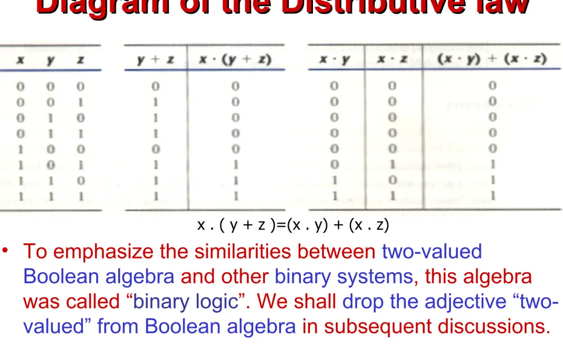
Diagram of the Distributive law
Diagram of the Distributive law
• To emphasize the similarities between two-valued
Boolean algebra and other binary systems, this algebra was called “binary logic”. We shall drop the adjective “two-valued” from Boolean algebra in subsequent discussions.
BASIC THEOREMS and PROPERTIES
BASIC THEOREMS and PROPERTIES
OF BOOLEAN ALGEBRA
OF BOOLEAN ALGEBRA
• If the binary operators and the identity elements are interchanged, it is called the DUALITY
PRINCIPLE. We simply
interchange OR and AND operators and replace 1 ’s by 0’s and 0’s by 1’s
.
BASIC THEOREMS and PROPERTIES
BASIC THEOREMS and PROPERTIES
OF BOOLEAN ALGEBRA
Boolean Functions
• A binary variable can take the value of 0 or 1.
• A Boolean function is an expression formed with binary variables, the two
Boolean Functions
• An example of Boolean function: • F1(x,y,z) = xyz’
Algebraic Manipulations
• A literal is primed or unprimed variable. When a Boolean function is implemented with logic gates, each literal in the function designates an input to a gate, and each
Simplifying Boolean Functions
Canonical & Standard Forms
5th• Canonical Forms – Sum of Minterms
– Product of Maxterms
• Standard Forms
Canonical Form
• Minterm
– n variable forming an AND term, with each
variable being primed or unprimed that provide 2n possible combinations.
• Maxterm
– n variable forming an OR term, with each
Canonical Form of Boolean Function
• A Boolean function may be expressed algebraically from a given truth table by
Canonical Form of Boolean Function
• For example, the function f1 in the table 2-4 is determined by expressing the
combinations 001, 100, and 111 as x’y’z,
xy’z’, and xyz, respectively. Since each of
these minterms results in f1=1, we should have
• f1= x’y’z+ xy’z’+ xyz
• f1= m1 + m4+ m7 f1=Σ(1,4,7)
Product of Maxterm
• Now consider the complement of Boolean
function, it may be read from the truth table by
forming a minterm for each combination that produces a 0 in the function and then ORing
those terms. The complement of f1 is read as:
• f1’= x’y’z’ + x’yz’+ x’yz + xy’z+ xyz’ = Σ(0,2,3,5,6)
• f1= (x+y+z)(x+y’+z)(x+y’+z’)(x’+y+z’)(x’+y’+z) • f1= M0 . M2 . M3 . M5 . M6 f1=∏(0,2,3,5,6)
Conversion Between Canonical Forms
• Consider this function: F(A,B,C)=Σ(1,4,5,6,7) • This has the complement: F’(A,B,C)=Σ(0,2,3)
• Now, taking the complement of F’ by DeMorgan’s Theorem, we obtain
• F=(m0+m2+m3)’=(m0’m2’m3’)= M0M2M3= ∏(0,2,3)
• It is clear that the following relation holds true:
Standard Form
• The two canonical forms of Boolean algebra are basic forms that one obtains from reading a
function from the truth table.
• These forms are very seldom the ones with the least number of literals, because each minterm or maxterm must contain, by definition ALL the variables either complemented or
Standard Form
• Another way to express Boolean function is in
standard form, that may contain one, two or any number of literals unlike the canonical form.
• Sum of Products (SOP) is a Boolean expression containing AND terms, called product terms, of one or more literals each. The sum denotes the ORing of these terms.
Standard Form
• Product of sums is a Boolean expression containing OR terms, called sum terms. Each term may have any number of
literals. The product denotes the ANDing of these terms.
Integrated Circuit (IC)
• Digital circuits are constructed with integrated circuits.
• An Integrated Circuit (IC) is a small silicon semiconductor crystal, called chip,
containing the electronic components for the digital gates.
• The various gates are interconnected
Integrated Circuit (IC)
• The chip is mounted in a ceramic or plastic container, and connections are welded to external pins to form IC.
• The number of pins may range from 14 in a small IC package to 64 or more in a
Levels of Integration
• Digital ICs are often categorized according to their circuit complexity as measured by the number of logic gates in a single
package.
Levels of Integration
• Medium-scale Integration (MSI) devices have a complexity of approximately 10 to 100 gates in a single package.
Levels of Integration
• Large-scale integration (LSI) devices
contain between 100 and a few thousand gates in a single package.
Levels of Integration
• Very Large-scale integration (VLSI) devices contain thousands of gates within a single package.
• Because of their small size and low cost, VLSI devices have revolutionized the computer
system design technology, giving the designer the capabilities to create more complex
structures.
Digital Logic Family
• Digital integrated circuits are classified not only their complexity or logical operation, but also by the specific circuit technology to which they belong.
• Many different logic families of digital
Digital Logic Family
• The following are the most popular digital logic integrated circuits family:
• TTL transistor-transistor logic • ECL emitter-coupled logic
• MOS metal-oxide semiconductor • CMOS complementary MOS
Digital Logic Family
• TTL transistor-transistor logic
– is a widespread logic family that has been in operation for some time and is considered as standard.
– evolved from a previous technology that used diode and transistors.
• ECL emitter-coupled logic
– has an advantage in systems requiring high speed operation such as in supercomputers and signal
Digital Logic Family
• MOS Metal oxide semiconductor
– one most advantage of MOS are the high packing density of circuit and simpler processing technique during fabrication.
• CMOS Complementary MOS
– uses one PMOS and one NMOS transistor connected in a complementary fashion in all circuits.
Digital Logic Family
• The most important parameters that are evaluated and compared between Digital logic families are the following:
• Fan-out – specifies the max number of load or maximum load current.
• Power dissipation – is the power consumed by the gate • Propagation delay – switching time or response time
Positive and Negative Logic
• The binary signal at the inputs and outputs of any gate has one of two values, except during transition.
Positive and Negative Logic
• Choosing the high-level to represent logic-1 defines positive logic system,
END OF
END OF
CHAPTER 2
CHAPTER 3
CHAPTER 3
SIMPLIFICATION OF
SIMPLIFICATION OF
BOOLEAN FUNCTIONS
Map Method
• Boolean functions may be simplified by
algebraic manipulations as discussed in Section 2-4.
• However, this procedure of minimization is awkward because it lacks specific rules to
predict each succeeding step in the manipulative process.
Map Method
• The map method, first proposed by Veitch diagram and modified by Karnaugh, is also known as the “Veitch diagram” or the
“Karnaugh map”.
• The K-map is a diagram made up of squares.
3-Variable K-Map
• Simplify the Boolean function
3-Variable K-Map Guide
• One square represents a term of 3 literals. • Two adjacent squares represent a term of
2 literals.
• Four adjacent squares represent a term of 1 literal.
3-Variable K-Map
• Simplify the Boolean function
3-Variable K-Map
• Simplify the Boolean function
3-Variable K-Map
Given the following Boolean function:
F(A,B,C)=A’C + A’B + AB’C + BC
1. Express it in sum of minterms.
4-Variable K-Map Guide
• One square represents a term of 4 literals.• Two adjacent squares represent a term of 3 literals.
• Four adjacent squares represent a term of 2 literal.
• Eight adjacent squares represent a term of 1 literal.
Prime Implicants
• When choosing adjacent squares in a
map, we must ensure that all the minterms of the function are covered when
combining the squares.
• It is necessary to minimize the number of terms in the expression and avoid any
Prime Implicants
• Sometimes there may be two or more
expressions that satisfy the simplification criteria.
Prime Implicants
• Consider the following four-variable Boolean function:
Prime Implicants
• A prime implicant is a product term obtained by combining the maximum
possible number of adjacent squares in the map.
Prime Implicants
• Two adjacent 1’s form a prime implicant
provided that they are not within a group of 4 adjacent squares.
Prime Implicant
• Figure (b) shows all possible ways that the three
minterms (m3,m9,m11) can be covered with prime
implicants.