Design and test of flexible chassis automatic tracking steering system
Song Shujie
1,2,
Li Yining
3,
Qu Jiwei
3,
Zhou Wei
3,
Guo Kangquan
3,4* (1. College of Food Science and Engineering, Northwest A&F University, Yangling 712100, Shaanxi, China; 2. College of Food Engineering and Nutritional Science, Shaanxi Normal University, Xi’an 710119, Shaanxi, China; 3. College of Mechanical and Electronic Engineering, Northwest A&F University, Yangling 712100, Shaanxi, China;4. Shaanxi Engineering Research Centre for Agricultural Equipment, Yangling 712100, Shaanxi, China)
Abstract: In order to develop an innovative omnidirectional non-homonymic flexible chassis (FC), the four-wheel steering control method of FC was designed by a new concept called off-centered steering (OCS) and the automatic tracking steering system was analyzed. Novelty of this wheel concept lies in the non-conventional positioning of the steering axis and wheel axis. Additionally, the steering axis of steerable wheel was motorized with an on/off electrometrical brake to overcome a hyper-motorization issue inherent to the wheel’s geometrical properties and hold the steering position. Based on the off-centered steering characteristics of FC, the Wheatstone bridge was applied in the steering control system. The bridge resistances are used to track target steering angles and the actual steering angle, respectively. The output voltage of the bridge is exploited to adjust the wheel’s speed so that steering and automatic tracking could be achieved. Experiments at different speeds, loadings, and target steering angles were conducted. Results showed that the chassis can indeed be controlled independently and its steering range is from –90° to 90°, which indicated the automatic tracking steering system was effective. The electromagnetic lock (EL) can significantly improve the stability of the chassis and reduce the vibration. Loading has no significant effect on the accuracy of the steering angle and the time it takes to complete steering tasks. The time taken to complete a forward steering task showed a linear relationship with the required angles, but was independent of rotation speed; for backward steering, time was related to both target angles and rotation speed. The results presented in this research may provide a reference for the steering control strategies of the four-wheel individual drive and four-wheel (4WID/4WIS) vehicle in the future.
Keywords: electric vehicles, flexible chassis, four-wheel steering, automatic tracking, control system DOI: 10.25165/j.ijabe.20171005.2525
Citation: Song S J, Li Y N, Qu J W, Zhou W, Guo K Q. Design and test of flexible chassis automatic tracking steering system. Int J Agric & Biol Eng, 2017; 10(5): 45–54.
1 Introduction
Electric vehicles (EVs) have garnered increasing
Received date: 2016-04-13 Accepted date: 2016-12-04 Biographies: Song Shujie, Lecturer, research interest: agricultural robotics and food processing equipment and machinery, Email: [email protected]; Li Yining, PhD candidate, research interest: agricultural robotics, Email: [email protected]; Qu Jiwei, PhD candidate, research interest: agricultural robotics, Email: [email protected]; Zhou Wei, Master graduate candidate, research interest: agricultural robotics, Email: [email protected]. * Corresponding author: Guo Kangquan, Professor, research interest: agricultural equipment and machinery. College of Mechanical and Electronic Engineering, Northwest A&F University, Yangling 712100, Shaanxi, China. Tel: +86-29- 87088712, Email: [email protected].
attention from researchers, developers, and consumers as
a response to the global energy crisis[1,2]. The
four-wheel individual drive and four-wheel individual steering (4WID/4WIS) EV offers better driving efficiency, flexibility, and maneuverability by virtue of its wheels being independently driven and steered by electric motors instead of the traditional integrated driving system and
steering mechanism[3]. The FC is a 4WID/4WIS EV
with in-wheel motors (IWM) that is suited to narrow roads within semi-closed or closed environments at low speed due to its omni-directional running capability.
motor-assisting, either direct-steering by the motor and gear unit or by other devices connected to the steering motor. Many previous researchers have made valuable contributions to the literature in this field. For instance,
Eze Corp Ltd. in Australia[4], Kanazawa Institute of
Technology[5], Yokohama National University[6], the
University of Tokyo in Japan[7], and Pusan National
University[8] in Korea. There are several research
institutions currently focusing on this method in China, as well, including Nanjing University of Aeronautics and
Astronautics[9], the Advanced Robotics Laboratory at
Chinese University of Hong Kong[10-13], Shenzhen
Automobile and Transportation Engineering Vocational and Technical College[14-17], Jilin University[18-20], School
of Control Science and Engineering College[21-24],
Changsha University of Science and Technology[25,26], and Southwest Jiaotong University[27].
Any existing steering control methods for 4WIS/4WID EVs require that a steering motor should be used, either directly or indirectly, thus requiring a complex control circuit and preventing the EV from making any turn while moving. This research proposed an automatic tracking steering system based on an off-centered steering axis without using a steering motor. One of the two bridge arms provides the tracking signal of the target angle while the other arm allows IWM position tracking. IWM speed is controlled by the output voltage of the bridge, i.e., changes in the relative angle of the wheel and the chassis frame to facilitate automatic tracking steering.
2 Mechanism and principle of automatic
tracking steering
FC, developed at Northwest A&F University and shown in Figure 1, is symmetrical and is made of four independent articulations. FC’s main technical parameters are listed in Table 1. Each articulation part combines an OCS axis, a pair of shock absorbers, an EL (FBD-050, from Taiwan KAIDE), and a DC brushless motor wheel (IWM from BATTLE, its main technical parameters are shown in Table 2), which has three degrees of freedom (DOF) (propulsion, direction and rotation). The OCS wheel plane is parallel to the
steering axis but does not contain it. In addition, the steering axis and wheel axis intersect in one point. The leg can rotate 180° round its attachment point (as shown in Figure 2). Once an articulation is placed at the right position, the system is designed to keep it in position with the use of an EL. A passive vertical suspension made of springs is used to connect the steerable wheels to the chassis, allowing the wheels to keep contact with the ground on uneven surfaces. FC can change its direction using differential steering, or by changing the direction of its articulations, making the chassis omni-directional and allowing it to move in tight areas (narrow environment). Many other configurations can be imagined and the 12 DOF on FC gives the chassis great flexibility and versatility in its locomotion capabilities.
1. Chassis 2. Off-centered steering axis 3. EL 4. Shock absorber 5. IWM Figure 1 Flexible chassis sample vehicle
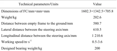
Figure 2 FC omni-direcitonal capabilities (top view) Table 1 Main technical parameters of the flexible chassis
Technical parameters/Units Value
Dimensions of FC/mm×mm×mm 1602.3×1342.5×705.8
Weight/kg 202.6 Distance between empty frame to the ground/mm 580.7
Lateral distance between the steering axis/mm 610.5 Longitudinal distance between the steering axis/mm 1 210.6
Working speed/m·s-1 0.5-3.6
Table 2 Main technical parameters of the IWM and its tire
Technical parameters/Unit Value
Rated power/W 500
Rated voltage/V 48.0
Rotation speed range/r·min-1 10-500 Adaptation tire size/mm×mm 160×30
inflation pressure/MPa 0.15
2.1 Automatic tracking steering structure
In order to minimize resistance to the steering structure, the conventional steering shaft is generally coplanar to the wheel rotation plane; an off-centered bias, conversely, leaves a certain distance d from the wheel motion plane without using a steering motor (as shown in Figure 3). An off-centered automatic tracking bias device consists of an IWM, off-centered axis, and wheel supporting mechanism, pair of gears, an EL, and angle detector resistor. When the IWM rotates around the OCS axis, the gears rotate following the axis, driving the detection resistor R1. The principle is that changes in
resistance R1 track the steering position of the IWM; a
precision multi-turn potentiometer detects rotation angle resistance.
1. Off-centered axis 2. Electromechanical brake 3,5. Gears 4. Multi-turn potentiometer 6. IWM
Figure 3 Location tracking structure on off-centered wheel (front view)
2.2 Determination of angle range
According to the FC operation and road conditions, this study was mainly focused on the low-speed steering Ackerman principle in terms of determining the respective off-centered axis steering angle range in different motion situations. (The high-speed model, our other ostensible option, is not appropriate for the FC.)
The Ackerman-principle-based model is shown in Figure 4. Only the right-turn situation was analyzed here to save space, as right and left turns are symmetrical.
O refers to the barycenter in an ideal state, O' refers to an instant turning center, αi (i=1,2,3,4) is the steering
angle of the ith off-centered wheel, Ri (i=1,2,3,4) is the
radial rotation of the wheel (for instant center), R is the turning radius of the barycenter, a and b refer to the horizontal distance between the extended line of the instant center and front and rear axle, W is tread, L refers to the wheel base, vi (i=1,2,3,4) is the linear velocity of
the ith wheel (for instant center), and r is distance between the right wheel and instant center.
Figure 4 Low-speed steering model based on Ackerman steering principle
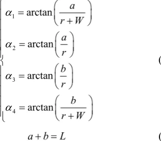
The geometric equations of the four-wheel steering angle are as follows:
1
2
3
4
arctan
arctan
arctan
arctan
a r W
a r b r
b r W
α
α
α
α
⎧ = ⎛ ⎞
⎜ ⎟
⎪ ⎝ + ⎠
⎪
⎪ ⎛ ⎞
=
⎪ ⎜ ⎟
⎪ ⎝ ⎠
⎨
⎛ ⎞
⎪ = ⎜ ⎟
⎪ ⎝ ⎠
⎪
⎛ ⎞
⎪ =
⎜ ⎟
⎪ ⎝ + ⎠
⎩
(1)
a b L+ = (2) Taking into account the real-world steering situation, the value ranges of each parameter are:
0 ≤a≤L
0 ≤b≤L
When r = 0, the chassis is in the pivot turn, and when r = +∞, the chassis moves in a parallel manner. Equation (1) shows that each wheel’s steering angle range is:
–90°≤αi≤90°
where, i = 1,2,3,4.
2.3 Principle of automatic steering
The automatic tracking steering system based on a bridge circuit is shown in Figure 5. It mainly consists of a micro control unit (MCU), step motor, bridge circuit, IWM, and motor drive controller. When the FC wheels turn, the MCU controls the step motor to rotate to the desired angle, then bridge arm resistance R2 is changed by the step motor creating imbalance in the bridge; the output of the bridge voltage and the signal controlled by the MCU are superimposed to cause the IWM to accelerate or decelerate. The EL is released so that the off-centered steering axis rotates around the frame structure, then the other arm bridge resistance R1 changes
with the rotation and the bridge is restored to balance. The output voltage of the steering bridge reflects the difference between the steering axis and the target position, and the difference is constantly fed back to the drive controller. The controller continuously adjusts the speed of wheel to follow the real-time balance position signal automatically. When the target angle is reached, the EL switches back on again.
Note: Ri are bridge resistance and i =1/2/3/4. R0 is the zero compensation
resistors.
Figure 5 Automatic tracking steering schematics based on Wheatstone bridge
When bridge is balanced, the relationship between the resistances of four arms is:
1 2 3 4 2
R
R =R =R =R = (3)
(
2 4)
1 30
1 2 ( 3 4)
e
R R R R
U U
R R R R
− =
+ + (4)
where, Ri(i=1,2,3,4) is bridge resistance, Ω;R is the total
resistance of the potentiometer, Ω; Ue is supply voltage,
V; U0 is output voltage, V.
According to the analysis above, the steering angle range is –90° to 90°. The rotation angle of the stepping motor is θ and the transmission ratio of the gear
is 10, so θ ranges from –900° to 900°. Change in
relative resistance at the potentiometer is calculated as follows:
360
R R
N
θ
Δ = × (5)
where, N is the rated total number of turns and 0≤N≤10.
Because the bridge is a half-bridge, U0 can be
integrated into Equation (2) to yield the following:
0
4 i 2 e 2 2 e
R R
U U U
R R R R
Δ Δ
= =
+ Δ + Δ (6)
From Equations (1), (3) and (4), the relationship of stepper motor rotation angle θ and bridge output voltage
U0 can be written as follows:
0 7200 2 e
U θ U
θ
=
+ (7) Because –900°≤θ≤900° and Ue = 5 V, –0.833 V≤U0≤
1.731 V.
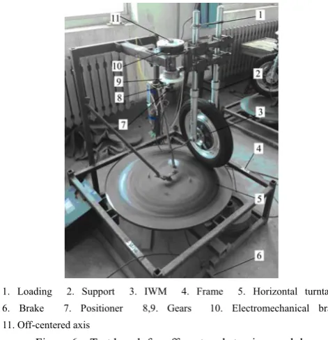
3 Test bench for steering experiment
1. Loading 2. Support 3. IWM 4. Frame 5. Horizontal turntable 6. Brake 7. Positioner 8,9. Gears 10. Electromechanical brake 11. Off-centered axis
Figure 6 Test bench for off-centered steering module
4 Control system design
The core control module (CCM) of the off-centered steering module and its test bench was developed using STM32F103VET6 (STMicroelectronics). A diagram of
the control system is shown in Figure 7. The rotation speed of the IWM based on the off-centered axis was controlled by superposition of the bridge and the core control signal; the superposition and amplification scheme is shown in Figure 8. According to the analysis in Section 1.3, the range of U0 is –0.833 V to 1.731 V.
In order to increase the sensitivity of the bridge circuit, the output voltage of the bridge was enlarged 5-fold then superimposed with the chip signal to control the IWM.
Figure 7 Steering control system
Figure 8 Bridge voltage amplification and superimposed scheme
The speed of the horizontal turntable was controlled by adjusting the Pulse Width Modulation (PWM)
wave[29,30] produced by the MCU via PID control
algorithm. Using the same control method, an EL (FBD-050, Taiwan Cade KAIDE) was used to adjust the supply voltage of the chip. The data acquisition system consists of an industrial control computer (610H, Advantech Technologies) which stored data and a data acquisition card (PCI8326B, Beijing Zhongtai Research Ltd). An angle sensor (WDS35D-4, An Zhou Electronics Ltd) was used to measure the signal of the
off-centered axis angle.
5 Results and analysis
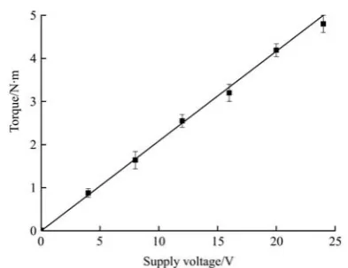
5.1 The EL test
maximum torque that caused the EL to rotate. Each value was measured in five replicates; the averaged results obtained are shown in Figure 9.
Figure 9 Relationship between supply voltage and EL static torque
By fitting the data in Figure 9, the relations can be obtained (R2=0.997):
0.051 0.201
L e
T = U + (8)
where, TL is the static tightening torque, N·m; Ue is
supply voltage, V.
According to the literature [33], the relationship of steering force and loading is:
0.0844 36.095
Z T
F = N + (9)
where, Fz is the steering force, N; NT is the loading
weight, N.
When the IWM rotates at uniform speed, then:
L Z
T =F d (10) where, d is the off-centered distance, m.
By combining the equations above, the relationship between the loading weight and supply voltage can be obtained:
0.363 150.98
e T
U = N + (11)
Then the supply voltage can be determined by the loading.
5.2 Influence of electromagnetic EL on steering
stabilization
In order to examine the effects of the EL on the steering stability, comparison tests were conducted with or without locking the EL. The experimental conditions were as follows: no loading, target steering angle of ±30°, and speed of 60 r/min.
The EL was unlocked after setting the target steering angle and while the stepper motor rotated. Unlocking
voltage was calculated via Equation (11). At the locking moment, the output voltage of the bridge was 0 and the voltage of EL was set to 24 V.
Figure 10 shows the curves of the steering angle with and without locking of EL. Locking did not affect the steering process. Without locking, the steering shaft began to shake at 0° and ±30°; when the EL was working, there was almost no vibration in the steering shaft. In short, steering with locking was necessary.
a. Impact of EL on forward steering
b. Impact of EL on backward steering Figure 10 Impact of EL on steering
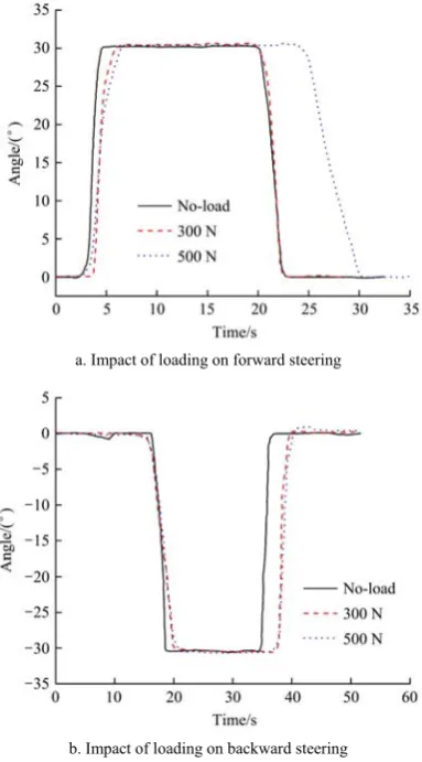
5.3 Effect of loading on steering angle
We tested various loading conditions to account for the fact that in real-world application, the FC sometimes must work under a load. The test conditions were as follows: no loading, 300 N and 500 N, respectively, at target angle of ±30°, basic speed of 60 r/min, and EL switched on with locking force which changed as the load changed.
speed, and the speed changing process did not change under different loads. At different target angles, the time taken for steering varied while the steering process was fairly consistent.
a. Impact of loading on forward steering
b. Impact of loading on backward steering Figure 11 Impact of loading on steering Table 3 Results of steering angles based on loading
Target
angle/(°) Loading/N
Average angle/(°)
Absolute
Error/(°) Time/s
30
0 30.39 0.39 3.148
300 30.41 0.41 3.286
500 30.31 0.31 3.043
Average value 30.37 0.37 3.159
Standard deviation 0.053 0.121
–30
0 –30.29 –0.29 3.195
300 –30.36 –0.36 3.574
500 –30.42 –0.42 3.645
Average value –30.36 –0.36 3.472
Standard deviation 0.065 0.242
Figure 12 shows the tire trend and its footprint when different test loading was applied. The contact area of tire footprint increased with test loading increasing. And due to the steering of wheel, But the footprint is asymmetric but is biased in favor of one side of the steering axis.
Figure 12 Tire trend and its footprint with different test loadings
5.4 Effect of speed on the steering angle
The chassis turns at a certain speed named the “basic speed” of the IWM. In order to analyze the influence of basic speed on steering angle, further tests with varying basic speed was conducted. The test conditions were: no loading, target angle of ±30°, basic speeds of 30 r/min, 60 r/min, 90 r/min and 120 r/min, and FC speed range of 30-120 r/min.
The test results are shown in Figure 13. It took about 3-4 s to reach target angle of +30°, where the accuracy of the angle was stable and independent of basic speed. The reason for this is that the speed changing process was stable with the fixed bridge output voltage. Basic speed had greater impact on negative target angles then positive ones: It took about 2 s to reach a target angle of –30°, for example. With fixed bridge output voltage and lower basic speed, the chip voltage and output voltage of the bridge were superimposed to less than zero, so the IWM speed dropped to 0 r/min, the horizontal turntable dragged the IWM, so the steering efficiency was low, i.e., steering took more time. With quicker basic speed (120 r/min, for instance) the chip voltage and output voltage of the bridge were superimposed to above zero, so the IWM also rotated and steering efficiency was higher.
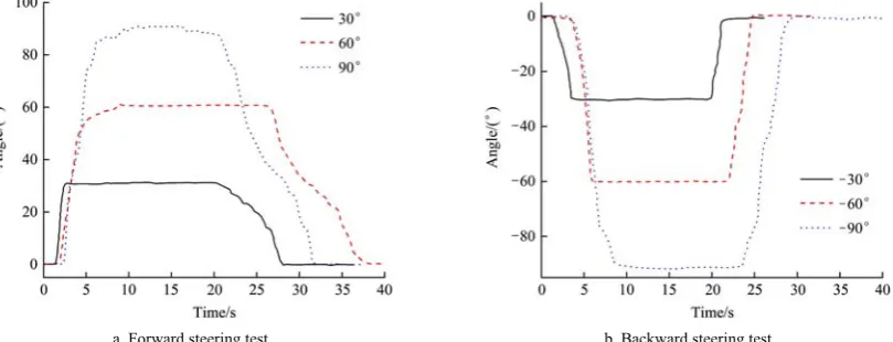
5.5 Test of different target steering angles
The steering angle range of each wheel in the FC is –90° to +90°. Another experiment with different target angles was conducted under the following test conditions: target angles of ±30°, ±60° and ±90°, no loading, and basic speeds of 30 r/min, 60 r/min, 90 r/min and 120 r/min.
target angle.
The results of the tests on different basic speeds with different target angles are shown in Table 4. When steering forward the target angle was positive and when
steering backward the target angle was negative. Although the basic speeds were different, the angle error was quite small. With fixed target angle, the time taken for steering was relatively fixed.
a. Impact of basic speed on forward steering b. Impact of basic speed on backward steering Figure 13 Impact of speed on steering without EL
a. Forward steering test b. Backward steering test
Figure 14 Testing different steering angles Table 4 Results of steering angle tests
Target angle/(°)
Loading /N
Average angle /(°)
Absolute
Error/(°) Time/s
Target angle/(°)
Loading /N
Average angle /(°)
Absolute
Error/(°) Time/s
+30
30 30.14 0.14 3.087
–30
30 –30.14 0.14 3.870
60 30.39 0.39 3.148 60 –30.29 0.29 3.196
90 30.23 0.23 3.104 90 –30.20 0.20 2.064
120 30.32 0.32 3.906 120 –30.12 0.12 2.034
Average value 30.27 3.311 Average value –30.19 2.791 Standard deviation 0.1086 0.397 Standard deviation 0.0763 0.900
+60
30 60.23 0.23 8.043
–60
30 –60.23 0.23 4.867
60 60.43 0.43 7.945 60 –60.37 0.37 3.794
90 60.12 0.12 7.988 90 –60.34 0.34 2.625
120 60.34 0.34 8.123 120 –60.12 0.12 2.662
Average value 60.36 8.025 Average value –60.39 3.487 Standard deviation 0.266 0.0768 Standard deviation 0.332 1.068
+90
30 88.43 –1.57 11.403
–90
30 –88.23 –1.77 5.987
60 88.65 –1.35 11.507 60 –88.98 –1.02 4.724
90 88.23 –1.77 11.608 90 –88.54 –1.46 3.967
120 88.38 –1.62 11.612 120 –88.75 –1.25 3.924
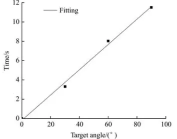
The relationship between the target angle and time taken for steering was linear during forward steering, as shown in Figure 15. Linear fitting analysis was applied accordingly (R2= 0.993):
0.1308 0.1745
A A
t = θ − (11)
where, tA is the time taken to steer to the target angle, s; θA is the forward steering angle, rad.
Figure 15 Time taken to steer forward versus target angle
The relationship between target angle, time taken for steering, and basic speed was linear, so a two-factor linear analysis was applied (R2 = 0.963):
0.0308 0.0337 4.0727
M M
t = − θ − n+ (12)
where, tM is the time taken to steer to the target angle, s; θM is the backward steering angle, (°); n is rotation speed,
r/min.
To verify Equations (11) and (12), a comparison between the calculated values and test values at 100 r/min with a target angle of ±10° and at 70 r/min with a target angle of ±45° was established, as shown in Table 5. The results indicated that the relative error was small, i.e., those Equations (11) and (12) fit the data very well.
Table 5 Steering angle test results
Target angle/(°)
Rotation
Speed/r·min-1 Calculated time/s Test time/s Relative Error/%
–45 70 3.010 3.105 3.16
–10 100 1.011 1.042 3.07
+10 100 1.134 1.094 3.53
+45 70 5.712 5.701 0.19
6 Conclusions
From literature review, any existing steering control methods for 4WIS EV require steering motors either directly or indirectly, thus requiring a complex control circuit or preventing the EV from making any turn while moving. Automatic tracking steering system for FC
does not need any steering motors and could make turns while running.
The most notable conclusions of this study can be summarized as follows:
1) A new steering method was developed based on an off-centered structure and bridge circuit, and a unique test bench was designed to test the steering process.
2) The angle range of the off-centered steering axis is –90° to 90°.
3) Utilizing an EL can significantly improve the stability of the FC’s steering process and reduce the vibration.
4) Loading has no significant effect on the accuracy of the steering angle and the time it took to complete steering tasks.
5) During forward steering, the time taken to steer is speed-independent and is linear only with the target angle; while during backward steering, time has a relationship with both basic speed and target angle.
Acknowledgements
This work was supported by the National Natural Science Foundation of China (Grant No. 51375401). We would also like to thank all the postgraduate students who provided valuable laboratory work and other support to this study.
[References]
[1] Lu D, Guo K Q. Divert cal motion model of flexible chassis. Journal of Agricultural Mechanization Research, 2011; 33(4): 219–222. (in Chinese)
[2] Lu D. Research and development for flexible chassis and its control system of conservatory work machines. Master’s dissertation. Yangling: Northwest A&F University, 2011. (in Chinese)
[3] Qiu Y J. Status quo and development of farm produce processing industry in China. Agricultural Science & Technology and Equipment, 2009; 1: 71–72, 75. (in Chinese) [4] Corp E. Smart-wheel Technology. 2002.
[5] Oshima H, Tani M, Kobayashi N, Ishii A, Imai K. Control for four-wheel individual steering and four-wheel driven electronic vehicle. Electrical Engineering in Japan, 2005; 153(3): 71–78.
distribution of rear wheels. 11th IEEE International Workshop on Advanced Motion Control, 2010.
[7] Wang Y, Nam K, Fujimoto H, Hori Y. Robust roll and yaw integrated control using 4 wheel steering based on yaw moment and lateral force observers. IEEJ Research Information, 2011; 134: 25–30. (in Japanese)
[8] Choi M W, Park J S, Lee B S, Lee M H. The performance of independent wheels steering vehicle (4WS) applied Ackerman geometry. 2008 ICCAS International Conference on Control, Automation and Systems, 2008. [9] Zhang J, He X M. 360° four-wheel steering electric car
design. Highways & Automotive Applications, 2007; 1: 1–4. (in Chinese)
[10] Lam T, Qian H, Xu Y. Direct yaw moment control for four wheel independent steering and drive vehicles based on centripetal force detection. IEEE International Conference on Robotics and Automation (ICRA), 2012.
[11] Lam T L, Qian H H, Xu Y S, Xu G. Omni-directional steer-by-wire interface for four wheel independent steering vehicle. IEEE Int Conf Robot, 2009; pp.1655–1660. [12] Lam T L, Xu Y S, Xu G Q. Traction Force Distribution on
Omni-directional Four Wheel Independent Drive Electric Vehicle. IEEE Int Conf Robot, 2009; pp.1661–1666. [13] Lam T L, Qian H, Xu Y. Omnidirectional Steering
Interface and Control for a Four-Wheel Independent Steering Vehicle. IEEE/ASME Transactions on Mechatronics, 2010; 15(3): 329–338.
[14] Ren S, Dong Z, Qiu H, Li Z, Qi Z T. Parameterization analysis for a four in–wheel–motors drive and four wheels independent steering electric vehicle based on multi–body inverse kinematics. International Journal of Biomechatronics and Biomedical Robotics, 2013; 2(2-4): 124–134.
[15] Deng Z J, Dong Z R. Research on stability simulation for four-wheel independent steering Electric Vehicle. Advanced Materials Research, 2012; 512-515: 2657–2661. [16] Deng Z, Qi Z T, Dong Z R, He P, Han C W, Ren S Y. A
road surface identification method for a four in–wheel–motor drive electric vehicle. International Journal of Biomechatronics and Biomedical Robotics, 2013; 2(2-4): 87–92.
[17] Zhu X, Qiu H, Dong Z, Qi Z T, Zhang Y. Steering coordination control of front wheels for a four in–wheel–motor drive electric vehicle. International Journal of Biomechatronics and Biomedical Robotics, 2013; 2(2-4): 75–80.
[18] Zong C F, Liu J W, Zheng H Y, Song P, Zhang Q. Modeling and special conditions simulation of electric vehicle with 4WID/4WIS. Automotive Engineering, 2011; 33(10): 829–833. (in Chinese)
[19] Liu J W. Study on stability integrated control algorithm of driving/steering/braking systems for four-wheel-independent electric vehicle. PhD dissertation. Changchun: Jilin University, 2012. (in Chinese)
[20] Chen G Y. Research on experiment platform of by-wire electric vehicle with four wheels independent control and its integrated chassis control strategy. PhD Dissertation. Changchun: Jilin University, 2012. (in Chinese)
[21] Yang F G, Ruan J H, Li Y B, Rong X W, Qiu X Y, Yin Z F. 4WID- 4WIS vehicle yaw control based on fuzzy logic control of AFS+ARS+DYC. Transactions of the CSAM, 2011; 42(10): 6–12. (in Chinese)
[22] Yang F G. Research on anti-skid and yaw stability control of 4WID/4WIS electrical vehicle. PhD dissertation. Jinan: Shandong University, 2010. (in Chinese)
[23] Ruan J H, Li Y B, Yang F G, Rong X W. Path tracking control of high-speed 4WID-4WIS autonomous vehicle. Robot, 2011; 33(4): 411–418, 433. (in Chinese)
[24] Ruan J H, Li Y B, Yang F G, Rong X W. Single-point preview control for unmanned high-speed 4WID-4WIS vehicle path tracking. Journal of Chongqing University: Natural Science Edition, 2011; 10: 21–26. (in Chinese) [25] Qiu H, Lei Z B, Qi T Z M, Dong Z R. A novel design of a
suspension system for Omni-directional electric vehicles. Advanced Materials Research, 2011; 308-310: 1826–1831. [26] Qiu H, Qi T Z, Lei Z, Dong Z R. A novel design of an
electric vehicle with lateral moving and in situ steering. 2011 Second International Conference on Mechanic Automation and Control Engineering (MACE), 2011.
[27] Li X P, Zhang Z T. Design, modeling and simulation of a novel Omni-directional steering system. 2013 2nd International Conference on Mechatronics and Control Engineering, ICMCE 2013.
[28] Yang L, Guo K Q, Ding X M. The steering control system design of flexible chassis for conservatory work based on bridge circuit. Journal of Agricultural Mechanization Research, 2013; 35(9): 151–155. (in Chinese)
[29] Chen W K, Chen Z, Wang Z, Gao Y W, Tian T, Gao Y X. Control system design of omni directional electric chassis. Transactions of the CSAM, 2013; 44(6): 19–23, 34. (in Chinese)
[30] Meng Q H, Xu J, Wang D F. Power system of electric vehicle driven by in-wheel motors. Transactions of the CSAM, 2013; 44(8): 33–37, 20. (in Chinese)
[31] Lu W, Guo K H, Zhang J W. Feed-forward integrated with fuzzy PID feedback current control algorithm in electric power steering. Transactions of the CSAM, 2010; 41(8): 10–15. (in Chinese)
[32] Zhang W C, Zeng X J. Research on vehicle chassis dynamometer of MCG-200 based on fuzzy-PID. Transactions of the CSAM, 2006; 37(12): 17–19, 45. (in Chinese)