Offshore Operations in Marine GeoSciences
Seabed Sediment Sampling Techniques
Andy Wheeler, University College Cork, School of Biological
Earth & Environmental Sciences
[email protected]
1. Introduction
Seabed sampling can be undertaken for a range of objectives; to directly sample the seabed sediments or to sample the epifauna and infauna contained, to sample the surface layers only or to penetrate into deeper layers. Note that reference to “the seabed” in this on-line lecture can be replaced by reference to estuary, river and lake beds where all are equally applicable.
There are a range of sampling techniques available that are of differing benefits depending on the specific requirements of the study. Coring and drilling are obviously of benefit if penetration is needed to access older and deeper sediments (and rocks). Box-cores, multicores, grabs and dredges have different benefits and limitations in sampling seabed surface sediment. Sample types and the purpose of the survey is therefore a crucial consideration. See also
http://www.ga.gov.au/marine/survey-techniques/sedimentary-coring-drilling.html.
Another key practical consideration when designing a seabed sampling campaign is the limitation of the vessel in operating the gear-type (sampling devices). As a general rule of thumb, the bigger the vessel, the more stable the platform and therefore the better for doing any type of sampling. In practical terms, however, bigger vessels are more costly. Nevertheless, some types of sampling can be performed from small vessels, even over the side of RIBs (Rigid Inflatables) by hand-hauling in relatively shallow waters. For deeper water, a winch will be required. Remember that the rope (or in most cases a metal cable) has to be able to carry not just the weight of the coring device but the weight of the cable itself. If sampling in deep marine environments, the weight of a 1000m or even 4000m cable is not trivial and may become a limitation of the power of winch.
Clearly, specialist vessels are required to drill into rock and heavy lifting winches or A-frames are required to deploy heavy gear such as vibro-cores. For all sampling types vessel stability is important. Bringing sampling equipment back on deck in rough weather can be hazardous and all operations have a maximum sea-state (depending of the motion of the vessel and its configuration) after which deployment and especially recovery is no longer safe. Catamarans make good sampling vessels as they are stable. Sampling is always preferably done from side-winches located mid-ship, if available. For lifting heavier gear or recovering from deeper water (remember you have to factor in the weight of the cable also), it may be necessary to deploy and recover off a stronger A-frame over the stern. This means there will be more vessel pitch and potential vessel roll implications.
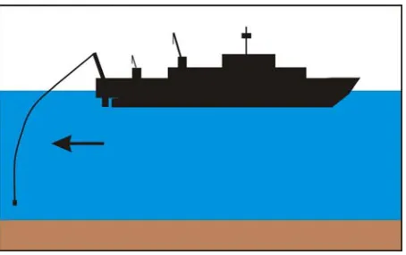
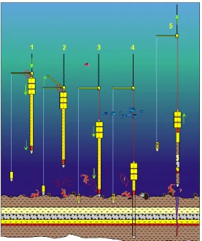
A third key consideration is the required positional accuracy of the sample. If your sampling target is large (e.g. you are groundtruthing a big patch of seabed of uniform sediment properties as revealed in your seabed mapping programme), then the vessel’s position may be fit for purpose. In deep waters, it can be assumed that the weight of the cable will pull the sampling device straight down (providing the vessel is not drifting), so vessel position is a good approximation of the sample position. If you are in shallow water with strong currents then the cable may be pulled away from the vessel downstream. This will be obvious as you will see the angle on the cable from the surface. It is very difficult to use that angle to make an offset calculation as the wire will catenate (see Figure 1). These problems can be minimised by letting the vessel drift with the current over the sampling site and deploy “on the drift”.
2). The vessel will range to the transponder to accurately determine the exact location of the sample. In real-time, this can be done to accurately target the sampling operation on the seabed. To a similar end, downward facing real-time video cameras can be used to inspect the seabed and decide where to specifically lower the device. With ROVs (remotely-operated vehicles), a real-time presence on the seabed lends itself to an extremely effective “search and sample” operations.
Figure 1. The effect of currents on wire catenation (bending the wire). Note the weight of
the cable eventually pulls the cable down straight and wire angle at the top cannot be simply used to predict the location of the sampler. Source: A. Wheeler
Figure 2. An example of a USBL underwater navigation configuration. Note the ships
transceiver ranging to the two transponders (in this case on an ROV and ROV garage). Such systems can be used to accurate position sampling gear on the seabed so you know exactly where you took your sample.
2. Drilling technologies
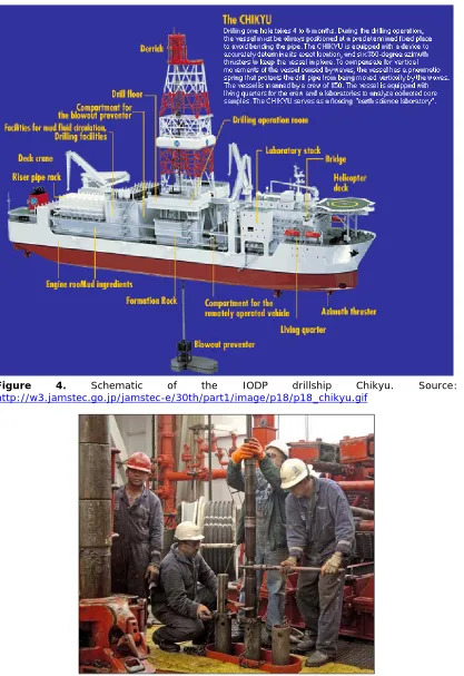
In order to penetrate more than several metres into the seabed, or to sample lithified sediments (rock), it is necessary to drill. Drilling is very costly and requires specialised skills and large stable vessels that are able to hold their position at sea (dynamic vessel positioning) so as not to bend the drill rods. Figure 3, 4 & 5 show the RV Chikyu that is the premier scientific drillship operated by IODP (Integrated Ocean Drilling Programme).
Figure 3. The IODP drillship Chikyu, capable of drilling into the seabed (sediment and
rock) to a depth 7 kilometres with near-full core recovery. Source:
http://subseaworldnews.com/wp-content/uploads/2012/03/Japan-JAMSTECs-Chikyu-Vessel-Set-Sail-for-IODP-Expedition.jpg
This drillship is capable of drilling seven kilometres into seabed and was designed to attempt to drill into the active subduction zone below the Nankai Trench, offshore Japan. Unlike oil rigs that simple drill holes, scientific drill ships need to recover intact cores which is much more difficult and achieve this by drilling with hollow corers. The Chikyu is equipped with a riser unit which means that the drill does not go up and down as the vessel rides the waves, this allow continuous even drilling.
Figure 4. Schematic of the IODP drillship Chikyu. Source: http://w3.jamstec.go.jp/jamstec-e/30th/part1/image/p18/p18_chikyu.gif
Figure 5. The drilling team on the deck of the RV JOIDES Resolution. Source:
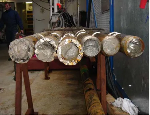
Figure 6. Core ends showing sediment fill. Note: the three of the left where acquired by
rotary drilling – note the teeth on the outside of the barrel, the three on the right were from piston coring (see below). Source: A.Wheeler
To get around the need to mobilise large drill ships at a day rate of several 10s of 1000s of Euro per day, MARUM (University of Bremen) have build a seabed deployable drill rig called MeBo (Figure 7 & 8). The British Geological Survey operate a similar device called Rockdrill. It can be lowered to the seabed, the legs extend to make it a stable and vertical platform from which it can start drilling by being remotely controlled from the vessel. Individual filled core barrels are stored on a magazine on the rig at the seabed so it can drill down several barrel lengths to a maximum depth of 50m. MeBo2 is now under development.
Figure 7. MeBo deployable drill rig with extendable legs for deep seafloor coring.
Figure 8. MARUM’s drilling rig (MeBo) at the stern of the RV Celtic Explorer. MeBo can be
deployed onto the seabed and then drill down 10s of metres. Source: MARUM, Uni. Bremen
3. Coring technologies
If sediments are unconsolidated and penetration is required, then coring is the optimal technique of which there are two main methods: piston coring and gravity coring. Coring is considerably cheaper than drilling. Piston coring has an advantage over gravity coring it that it does not cause (if set correctly) compression of the sediments.
Figure 9. Three possible coring scenarios: gravity-type, perfect piston (no piston
Piston Coring
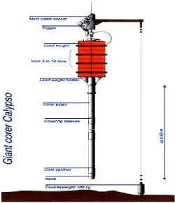
Piston corers can usually penetrate several metres to over 10 m. An exceptional piston corer, IFREMER’s Calypso corer, can penetrate over 20 m (Figure 10). The piston corer is lowered to the seabed. When the counterweight hits the seabed it triggers the main corer which freefalls to the seabed. It then rams into the seabed. The weights at the top of barrel ensure that it rams in with force to ensure penetration. The clever part of the piston corer is that inside the core barrel is a piston which is at the nose of the barrel (seabed end) when it hits the seabed. The piston is attached to the main cable and the height the corer drops is fine-tuned by the length of the counter-weight cable. This is such that when the corer first hits the seabed the piston is drawn up the inside of the barrel as the outer core barrel penetrates the seabed thereby maintaining a vacuum within the barrel. The core barrel penetrates the seabed and the sediment is pushed and sucked into the barrel ensure maximum penetration and minimum compression (Figure 11).
Figure 10. The Calypso piston corer is capable of making sediment samples up to 22
Figure 11. Piston corer operations. (1) Before coring, the piston is lowered in the core
catcher. The piston cable is tightened up to the lever arm and its upper part is wrapped as an external loop. The length of the loop is equivalent to the free fall (from 1 to 3m) of the piston corer. (2) The landing of the counterweight releases the lead weight. The loop of the piston cable unwinds and the piston corer (pipes and lead weight) falls at G-speed. (3 & 4) On landing, with the nose of the piston corer at the surface of the sediment, the piston cable is fully tightened and the piston is stopped at the water/sediment interface. The coring pipes are pulled down by simple gravity and slide down the piston, avoiding a suction of the sediment. (5) The extraction of the piston corer is obtained by pulling up the main cable, the piston resting against the lead weight. The sedimentary column (piston core) is blocked inside the plastic liner by the security device of the core catcher. Source: http://www.mnhn.fr/mnhn/geo/Collection_Marine/moyens_mer/Engins_de_prele vements_eng.htm.
Figure 12. Close up of a core catcher at the end of the barrel stopping recovered
sediment from flowing out the end. Source: B.Dorschel
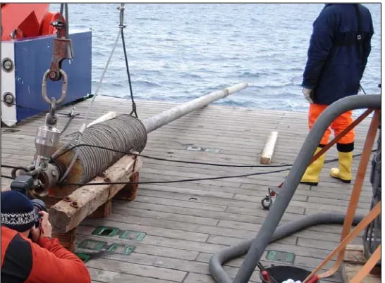
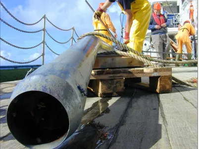
Gravity Coring
The second method of coring is gravity coring which differs from piston coring in that there is no internal piston to drive the core. In gravity coring, the barrel is simply rammed in by brute force and some compression to the sediment occurs (Figure 13).
Gravity corers have problems with sand which become firmer went hit by force resulting in minimal penetration. Gravels can also be a problem especially is coarse material gets suck in the barrel. Muds are ideal.
If stones are hit then there is a danger that barrels can become bent: the so-called “banana-core” (Figure 14). These are an expensive and time consuming hazard. It is good to make sure that good penetrable substrates are chosen before piston or gravity coring commences.
Figure 13. A gravity corer on deck. The maximum length of core is limited by the length
Figure 14. A bent piston core barrel cause by deployment on inappropriate substrates.
The so-called “banana-core”. Source: B.Dorschel
Vibrocorers
Figure 15. Vibrocorer being deployed on the RV Celtic Voyager. Note the motor at the top
of the core barrel used to shake the barrel into the sediment. Source; A.Wheeler
Box-corers
Box-corers can only penetrate the seabed to a maximum depth of 50cm (Figure 16). However, if you are interested in surface or recent processes then this may be acceptable. The box-corer has distinct advantages over deeper coring devices in that it can take a larger volume of sample (which can later be sub-cored) and that it can reveal a “nearly undisturbed” view of the seabed surface (minus very fine unconsolidated material that is blown away on impact – see multi-corers). Figure 17 shows recovered box-core samples with tubes inserted to take sub-samples and also the vertical profiles revealed (see also http://www.infomar.ie/surveying/GroundTruthing.php). The topography of the seabed is also evident, information that is not available from simple coring. The bottom image show a circular box-corer called a Reineck box-corer which has better penetration although vertical profiles cannot be inspect. This one is fully of cold-water coral.
Figure 16. Box corer on the deck. Sediment is collected in the 50cm x 50cm x 50cm “box”
in the centre. Note the lid with handle that can be lifted to aid inspection of the retained sediment. The side panels can be removed to allow the sediment vertical profile to be examined and sampled. Source: A.Wheeler
Figure 17. Opened box-core samples and a special circular box-corer called a Reineck
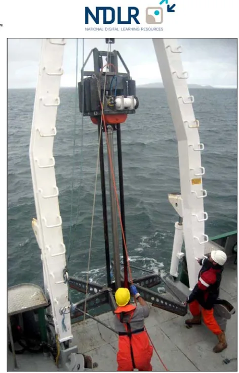
When deployed, the box-corer is cocked (see Figure 18) and lowered to the seabed where it free-falls the last few meters. On hitting the seabed, the opened box penetrates the seafloor. When the box is recovered, the swing arm cuts down into the sediment and close the base of the box, trapping the undisturbed sediment, before the box is hauled off the seabed.
Figure 18. Box corer being launched. Source: A.Wheeler
Multi corers
Multicorers are really miniature short piston corers. They are used by geologists, geochemists and biologists who wish to sample short undisturbed samples of the seabed. In particular, multicorers allow careful sampling of the sediment-water interface which most other corers blow away on impact.
creating a strong vacuum that retains the collected sediment and overlying near-seabed water. A swing arm then closes the base of the cores also to keep the sample intact on its transit to the sea surface (Figure 20).
Figure 19. A multicorer on deck. Source: A.Wheeler
Figure 20. Multicorer showing the sampling tubes filled with sediment and overlying
4. Grabs
There are many, many different types of grab. The principle is largely the same. The grab takes a bite out of the surface layer of seabed from which a bulk sample can been retained. A video ofa grab in operation can been seen on http://www.infomar.ie/surveying/GroundTruthing.php.
Essentially the grab freefalls to the seabed with its mouth open. When is hits the seabed it releases a trigger that allows the jaws to close as it is hauled back up (Figure 21).
Figure 21. Deployment and recovery of the Van veen grab. Source: http://www.geosi.no/pics/vanveen.gif
Figure 22. Van veen and hydraulic grab: two examples of the variety of similar grab
samplers.
The shipek grab is slightly different type of grab although it also takes a bulk sample by “biting a scoop” out of the seabed. The Shipek works on the principle of having a sprung-loaded rotating drum that, when released, springs around enclose a circular cavity. The cock the Shipek, the rotating drum is levered back and when it hits the seabed the cocked drum is released and a circular scoop is taken from the seabed (Figure 23..
Figure 23. Shipek grab being recove4red on deck. The closed drum underneath contains
the sediment sample.
The shipek has two distinct advantages, firstly it is much better in getting a sample from difficult substrates e.g. gravel or compacted sands. Secondly, if a stone gets trapped in the jaw, the samples does not wash out which often happens with grabs that don't close properly.
5. Dredges
For geological sampling, a dredge is used as a last resort when other sampling devices do not work. Dredges have distinct disadvantages in that they do not take a point sample but rather an accumulated sample from along the length of the towed line. They also do not give a representative sample as fines are washed out and coarse material grossly over-represented. However, for very coarse substrates (especially cobble-grade gravels) this may be the only way to get a sample. Also on rock seabed it many also be possible to pick up freshing eroded rock fragments. Dredges are therefore good for getting an idea of the types of coarse grained material on the seabed, an indication of possible maximum particle size and sampling associated epibenthic and encrusting biota.
There are a variety of geological dredges available, many of which are custom made and all work to varying and similar degrees. They often include wide-mesh metal nets and chains that ensnare particles often in conjunction with a trailing a metal cone (see Figure 24.)
Figure 24. Rock dredge being deployed.
6. Remote operated vehicles (ROVs)
In contrast to dredges, very precise sampling can be done with ROVs. ROVs are robotic instruments equipped with propulsion, manipulator arms, cameras and other sensors tethered to and controlled from a mother ship. Although ROVs are not suitable for deep coring, they can take surface sediments, shallow cores or pick-up individual clasts. Equipped with cutters they can in practice also be used to take targetted rock cores. A huge advantage with ROVs is that it allows an inspection of the seabed from which sampling sites can then be chosen. They are therefore very good at picking up specific specially chosen samples. They can also sample on vertical faces or from precipitous slopes where other coring devices would fail or be difficult to navigate.
A disadvantage of ROVs is that they are not cheap and may have to be operated from a large vessel with a specialist technical crew. They also have a limited payload, often not so much in terms of weight but in terms of storage containers or a core holding rack.
Samples can be picked up by using a manipulator arm controlled from the surface (see Figure 25). Although this is an excellent tool for taking really precise, and importantly carefully chosen samples, these arms are very difficult to control and sampling often takes a frustrating amount of time.
ROVs can also be equipped with conventional sampling devices such as pushcores (think multicorer) (see Figure 26) or mini box-corers. Empty push cores can be loaded into a “quiver” (or rack) on the ROV enabling several cores to be collected per dive. Again, these have to be picked up by the manipulators and pushed in vertically. A feat of somewhat time consuming dexterity for the ROV pilots.
Despite the distinct advantage of ROVs being able to work on steep or vertical terrain, to do sampling the ROV must be able to sit on the bottom to gain leverage.
Figure 23. VICTOR 6000 ROV sampling sediment at the base of a cold-water coral mound
with a pushcore.
7. Sediment traps
Sediment traps can be used to sample/trap the sediment that is falling onto seabed over a defined (duration of deployment) time interval (see Figure 27). Sediment falls into the funnel that has an area of 1m2 and is collected in a sample
bottle at the base. The sample bottle is usually poisoned with Mercury Chloride to stop biological growth. The sample bottles can be placed on a rotating carousel that is programmed to rotate at a pre-programmed interval e.g. every day, every month or every tidal cycle, for example.
The sediment trap is deployed on the seabed and, in shallow water, connected to a buoy on the surface. Recovery simply involves hauling the trap in from the buoy. Usually, however, the sediment trap is lowered to the seabed and released. To recover, an acoustic release system is used. The vessel communicates with the acoustic release which is triggered to either drop a weight, in which case the sediment trap comes back to the surface under its own buoyancy, or to release a float which comes to the surface as a buoy from which the device can be hauled in.
Figure 27. A sediment trap. Note the large funnel at the top and the carousel of sampling
bottles at the base. This device will sample sediment falling out of suspension onto the seabed over the deploy interval. The sample bottle carousel can move on at programmable intervals to enable the collection of samples at specified intervals e.g. per tidal cycle.