UTILIZING DIRECTIONAL ANTENNAS FOR AD HOC NETWORKING (UDAAN)
J. Redi and R. Ramanathan BBN Technologies
Cambridge, MA {redi|ramanath}@bbn.com
ABSTRACT
This paper describes the UDAAN system being developed at BBN Technologies as part of the DARPA/ATO Future Combat Systems (FCS) Communications program. The objective of UDAAN is to develop novel ad hoc networking protocols to support and exploit directional antenna technology. In particular, UDAAN delivers significantly improved performance - including higher effective capacity, lower latency, better connectivity and lower probability of interception/detection. UDAAN supports switched as well as steered beams, however, this paper focuses on switched beams. The UDAAN system consists of an integrated suite of separable, interacting modules which are implemented in a framework that allows sharing of code between simulation and real-life platforms. In this paper we describe the UDAAN protocols and their performance in both simulation and a real-world experiment.
INTRODUCTION1
Ad hoc networks have obvious significant tactical importance due to their flexibility and independence from existing infrastructure. Indeed, the defense community has been actively advancing ad hoc networking techniques since the early 80’s of the DARPA SURAN program [1]. To operate effectively in such a difficult environment, utilization of advanced technologies at all layers of the protocol stack becomes important. Along these lines, the
use of directional antennas has recently been proposed in
a number of forums for use in mobile ad hoc networks. Commercial cellular and fixed wireless systems have used directional antennas for many years due to their ability to increase spatial reuse, therefore increasing throughput, reducing delay, and reducing power output requirements. For a tactical ad hoc network, directional antennas can also provide advantages in terms of reduction in probability of interception and detection (LPI/LPD) due to their ability to focus transmissions in particular target directions, and in terms of increased anti-jamming (A/J) capability due to the ability of a receiver to increase gains in some directions, while creating nulls in others.
The DARPA/ATO Future Combat Systems Communications (FCS-C) program is in the process of developing and demonstrating a seamless, highly mobile, scalable, ad hoc network utilizing switch beams, steered beams, and frequencies that range from traditional military frequencies up to 38Ghz. Given the rapid timetable of the entire FCS program [2], this program has been tasked with making significant breakthroughs in all areas of communications within a very short time frame.
As part of this program, BBN has developed a completely new ad hoc networking suite, called UDAAN (Utilizing Directional Antennas for Ad Hoc Networking), which is explicitly designed to take advantage of frequency agile steered and switched beam directional antenna technology. We have developed our protocols using a code sharing method that allows us to experiment and design in a
simulation environment with the same code that can be
compiled and run in actual hardware. This allowed us as part of a team lead by TRW to instantiate, test, and demonstrate these protocols in a field experiment with 20 custom-built, highly mobile nodes at the Lakehurst Naval Air Warfare Center, in Lakehurst, NJ.
The research reported in this document was performed in connection with Contract/Cooperative Agreement number DAAD19-01-C-0027 with the U.S. Army Research Laboratory. The views and conclusions contained in this document are those of the authors and should not be interpreted as presenting the official policies or position, either expressed or implied, of the U.S. Army Research Laboratory or the U.S. Government unless so designated by other authorized documents. The U.S. Government is authorized to reproduce and distribute reprints for Government purposes notwithstanding any copyright notation hereon.
Link Characterization (linkchar) Module – The function of the link characterization module at each node is to evaluate the characteristics of each link in terms of
metrics (e.g. delay, interference caused, etc.). It does so by
gathering and analyzing tracerecords of transmitted and
received packets. Such tracerecords are available from the link layer, which creates these based on interactions with the physical layer. Link characterization will occasionally generate “probe” packets to assist in the determination of metrics in the absence of data packets, but typically just relies on the packets generated by other modules for metric evaluation. The analysis uses predictive filtering techniques to estimate the metrics, whose values are changed periodically to reflect the changes in the link characteristics. The metrics are classified according to the link profile (e.g., delay is 30 ms for T-BF link for the 2.4Ghz link), and conveyed to the routing module upon significant change.
RELATED WORK
Related work on ad hoc networking with directional or beamforming antennas has mostly been in the area of medium access control. Zander [3] has proposed the use of directional antennas in a slotted ALOHA multihop packet radio network. More recently [4] presents several medium access control protocols for fixed directional antennas. These protocols utilize physical location information to implement collision avoidance. Subsequently, [5] suggests a protocol that uses signal strength information instead of position information. In terms of routing, the use of directional floods to limit the scope of route requests in an “on-demand” ad hoc routing protocol is suggested in [6], and explored in [7]. Finally, an evaluation of the performance of an ad hoc network equipped with beamforming antennas from a systemic viewpoint was done in [8].
Our work is unique in that it is the first ad hoc networking
system using directional antennas (as opposed to addressing individual parts of a system). It is also includes the first high-fidelity simulation of a specific (non-stochastic) scenario. In addition, a number of innovations over prior work is present at each layer of the networking stack, as will be apparent in the forthcoming sections.
Directional Routing (droute) Module – The function of the routing module at each node is to generate routes to a given destination and, using this, initialize and update next-hop forwarding tables for use by the forwarding module. The route generation utilizes the metrics assigned by the link characterization module to support QoS-based routing. The routing scheme used is “proactive” and based on a scalable variant of link-state routing called Hazy Sighted Link-State Routing (HSLS), which was developed as part of the BBN DAWN project from the DARPA GloMo program. Very briefly, HSLS limits the propagation of link-state updates so that the timeliness of
SYSTEM COMPONENTS
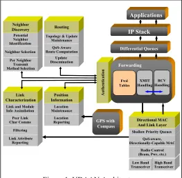
The UDAAN system is composed of a set of interacting mechanisms at the networking and MAC layers, as illustrated in Figure 1. We now present a brief overview of each module.
Authent ica ti on Forwarding Fwd Tables RCV Handling XMIT Handling IP Stack Applications Differential Queues Link Attribute Reporting Filtering Peer Link Char Comms Link and Module Info Assimilation Link Characterization Update Dissemination QoS-Aware Route Computation Topology & Update Maintenance Routing GPS with Compass Location Reporting Location Maintenance Position Information Per Neighbor Transmit Method Selection Neighbor Selection Potential Neighbor Identification Neighbor Discovery Low Band
Transceiver TransceiverHigh Band Radio Control (Beam, Pwr, etc.)
QoS-aware, Directionally-Capable MAC
Shallow Priority Queues
Directional MAC And Link Layer
Authent ica ti on Forwarding Fwd Tables RCV Handling XMIT Handling IP Stack Applications Differential Queues Link Attribute Reporting Filtering Peer Link Char Comms Link and Module Info Assimilation Link Characterization Link Attribute Reporting Filtering Peer Link Char Comms Link and Module Info Assimilation Link Characterization Update Dissemination QoS-Aware Route Computation Topology & Update Maintenance Routing Update Dissemination QoS-Aware Route Computation Topology & Update Maintenance Routing GPS with Compass Location Reporting Location Maintenance Position Information Location Reporting Location Maintenance Position Information Per Neighbor Transmit Method Selection Neighbor Selection Potential Neighbor Identification Neighbor Discovery Per Neighbor Transmit Method Selection Neighbor Selection Potential Neighbor Identification Neighbor Discovery Low Band
Transceiver TransceiverHigh Band Radio Control (Beam, Pwr, etc.)
QoS-aware, Directionally-Capable MAC
Shallow Priority Queues
Directional MAC And Link Layer
Low Band
Transceiver TransceiverHigh Band Radio Control (Beam, Pwr, etc.)
QoS-aware, Directionally-Capable MAC
Shallow Priority Queues
Directional MAC And Link Layer
Figure 1. UDAAN Architecture
Directional Neighbor Discovery (dneighbor) module – The function of the neighbor discovery module at each node is to determine the set of directly reachable nodes, and the means by which they can be directly reached.
Specifically, neighbor discovery establishes a set of links,
one to each neighbor, and qualifies each link by one or
more link profiles. Each link profile indicates a different
combination of transmit/receive properties that have been found to be sufficient for closing the link. A link profile
has two fields – band, and mode. There are up to 32
different bands, and three modes – No Beamforming (N-BF), only Beamforming (T-BF) and Transmit-and-Receive Beamforming (TR-BF). The neighbor discovery module establishes and maintains the “status” of each link profile and each link. It does so by periodically
sending heartbeats and “scoring” received heartbeats. A
the information is a linear function of the number of hops. HSLS is a simple, non-hierarchical, scalable routing protocol that has been well-studied and understood [9]. The routing module generates one next-hop forwarding table for each type-of-service (TOS). For each entry in each table, it also determines the values (the “radio profile”) the radio and antenna controllers must use to send to that neighbor to meet the ToS requirements.
Forwarding Module – The function of the forwarding module at each node is to, upon receiving an originated or in-transit packet, look up the next-hop entry in the relevant table (based on the destination and ToS), and send the packet to the link layer along with the radio and antenna parameters that must be used, including the band and the beamforming mode (e.g. T-BF).
Position Information (Posinfo) module – The function of the position information module at each node is to obtain the geographical position of a node and a set of tables describing the relative directions of each of the node’s neighbors. It interfaces with a GPS or similar position determination device to determine a node’s current location, and provides this information to dneighbor which includes the location in its outgoing heartbeats. When a node receives heartbeats from other neighbors, dneighbor provides the location contained in the heartbeat to the posinfo module. Posinfo then uses the current orientation of the node to generate a set of tables that the D-MAC layer can use for determining what direction to send the packet in.
Directional MAC (D-MAC) -- The Directional MAC receives the packet from the forwarding module and sends it out for transmission to the physical layer after performing the media access control functions. The MAC protocol is based on “unscheduled access”, that is, unlike TDMA schemes, no slot synchronization is required at the physical layer. Also, unlike TDMA schemes that may require a re-alignment of slot allocations as the nodes move, our approach is impervious to mobility. The MAC is in the same family of CSMA/CA as the IEEE 802.11 DCF algorithm in that it involves an RTS/CTS/Data/ACK handshake for sending a point to point packet. However, there are numerous important differences; chiefly that promiscuous RTS and CTS packet do not always cause neighboring nodes to back-off from transmitting and the use of a “forced idle-time” between successful transmissions to keep a single transmitter from unfairly dominating the channel. RTS packets are transmitted via a directional antenna and received by an idle node on its omni antenna. The receiver then switches its antenna towards the node than sent the RTS and transmits the CTS.
Directionally transmitted and received Data and ACK transmissions follow.
SIMULATION RESULTS
We have evaluated the performance of the UDAAN system using OPNET. For the network layer protocols including droute, dneighbor, linkchar, posinfo and forwarding, our model incorporates the exact same code as the one that runs in the target hardware – that is, there is no abstractions were done in the modeling of these modules. For the directional MAC layer, we have developed a very high-fidelity model that closely resembles the real-life system, including such parameters as antenna switching and transceiver turn-around time. The advantage of such detailed modeling is that we have found our simulation results to be an excellent predictor of real-life performance. One disadvantage, of course, is that simulation time can be very high, particularly with high traffic loads.
We report results on two scenarios that we shall call “Lakehurst” and “Stochastic”. The Lakehurst scenario consists of a 20 node simulation that closely models an actual test scenario which took place at the Lakehurst Naval Air Warfare Center in Lakehurst, New Jersey. The 20 nodes are organized in terms of two counter-rotating rings. The outer ring consists of 14 nodes, the inner ring consists of 5 nodes, and one node is stationary, representing a command center. The pathloss between communicating nodes was determined on-the-fly using the OPAR routines developed by MITRE [11]. OPAR takes a simple polygon description of the foliage and buildings as input, and uses well-accepted pathloss attenuation equations for both line of sight and obstructions to result in a moderately realistic attenuation model.
The traffic load for the Lakehurst scenario has 5
components: (1) two “A-B” pairs of adjacent nodes, full duplex at 250 kbps, (2) one “C-D” pair of nodes within the inner circle, full duplex at 150 kbps, (3) four high data rate position location information “HighPLI” streams of 40 kbps each, (4) fifteen low data rate position location information “LowPLI” streams at 0.8 kbps each, and (5) one “E-F” stream between randomly changing pairs of nodes, at full duplex 40 kbps. The total offered load is about 1550 kbps.
The Stochastic scenario is a 20 node randomly mobile
network, with an R4 stochastic propagation model. This
because, unlike the Lakehurst scenario, the highest data streams (e.g. A-B) required multihop forwarding.
Our radio model was based on a 1 Mbps radio. Each node had five antennas – one omni-directional and four directional. The directional antenna patterns had gains of about 16 dBi (except for the “front” of the vehicle where the gain was modeled as about 13 dBi due to interactions with the hood of the vehicle), and the omni gain was 6 dBi. We studied three performance metrics: throughput, average end-to-end latency (“delay”), and packet delivery ratio (PDR). The results are illustrated in Figures A, B and C, and discussed below.
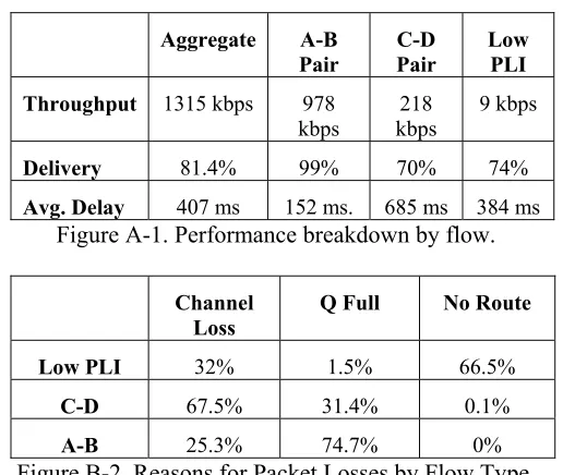
Figure A-1 shows the aggregate and component performance of UDAAN using the Lakehurst scenario. Not surprisingly, the A-B stream, which is single hop, had excellent completion rates and latencies, whereas the C-D and LowPLI flows, which were multihop, and experienced disconnection, had poorer performance.
Figure B-1 shows a bar chart of packet loss versus simulation time. We observe that the scenario has periods of very good performance interspersed with very bad ones – that is, performance depends upon which part of the scenario is under question. Figure B-2 shows the reasons for packet losses for each of the three flows – LowPLI, A-B, and C-D. Confirming our intuition, route failures dominate LowPLI losses, queue overflow dominates A-B losses, and channel drops dominate C-D losses.
Figure C-1 compares the performance of UDAAN when only a single omni-directional antenna (6 dBi) is used. Using directional antennas as described above gives a moderate improvement in throughput (10%) and delivery ratio (13%) and a more marked improvement in latency
(41%) for the given traffic scenario.
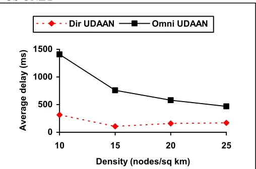
Making the traffic more challenging increases the relative performance of directional UDAAN in comparison to omni-directional UDAAN as can be seen from Figure D-1 and D-2. These simulations are based on the Stochastic scenario described earlier. We observe that using directional antennas provides up to 144% improvement in throughput in the range of considered densities, and a factor of 4.5 reduction in delay.
UDAAN w/Omni Directional is
Throughput 1194 kbps 10% better
Delivery 72.3 % 13% better
Latency 695 ms avg. 41% lower
Figure C-1. Performance of UDAAN using only a single omni antenna
Aggregate A-B
Pair C-D Pair Low PLI
Throughput 1315 kbps 978
kbps kbps 218 9 kbps
Delivery 81.4% 99% 70% 74%
Avg. Delay 407 ms 152 ms. 685 ms 384 ms
Figure A-1. Performance breakdown by flow.
Channel
Loss Q Full No Route
Low PLI 32% 1.5% 66.5%
C-D 67.5% 31.4% 0.1%
A-B 25.3% 74.7% 0%
0 500 1000 1500 2000 2500 3000
2 6 10 14 18 22 26 30 34 38 42 46 50 54 58
LowPLI loss C-D loss A-B loss
Figure B-1. Packet Loss vs. Time of Lakehurst Scenario.
The LowPLI losses are the bottom segment, the CD losses are the
Figure B-2. Reasons for Packet Losses by Flow Type.
IMPLEMENTATION EXPERIENCE
0 500 1000 1500
10 15 20 25
Density (nodes/sq km)
Aver
age
del
ay (
m
s)
Dir UDAAN Omni UDAAN
Figure D-2. End to End Delay vs. Node density when using either directional antennas or an omni antenna
0 20 40 60 80 100
10 15 20 25
Density (nodes/sq km)
Pa
ckets Delivered (%)
Dir UDAAN Omni UDAAN
Figure D-2. Packet delivery ratio vs. Node density when using either directional antennas or an omni antenna
output to control an antenna switch and the output of the radio was connected to an external power amplifier to assist the closing of long links.
[3] J. Zander, “Slotted Aloha multihop packet radio networks with directional antennas,” Electronic Letters, vol. 26, no. 25, 1990
Each networking router was connected to a government controlled laptop that used the MGEN/DREC applications from NRL [11] to generate the data traffic described in the simulation section. Extensive performance data on packet loss rate, throughput, and delay was taken on every run and compared against the baseline as well as simulation runs. Ultimately all the networking protocols performed exactly as expected and we were able to verify the advantages of directional antennas over omni antennas in a real operational scenario.
[4] Y.B. Ko, N. Vaidya, “Medium Access Control Protocols using Directional Antennas in Ad Hoc Networks,” Proceedings of IEEE Infocom, March 2000.
[5] A. Nasipuri, S. Ye, R.E. Hiromoto, “A MAC Protocol for Mobile Ad Hoc Networks Using Directional Antennas,” Proceedings of IEEE Wireless Communications and Networking Conference (WCNC), 2000
[6] Y-B. Ko, N.H. Vaidya, “Location Aided Routing (LAR) in
Mobile Ad Hoc Networks,” in ACM/Baltzer Wireless
Networks (WINET), Vol. 6, No. 4, pp. 307-322
[7] A. Nasipuri, J. Mandava, H. Manchala, R.E.Hiromoto, “On Demand Routing Using Directional Antennas in Mobile Ad
Hoc Networks,” in Proceedings of ICCN 2000, Oct 2000
Las Vegas
CONCLUSION
In this paper we have described the architecture of a new suite of protocols called UDAAN. These protocols have been developed as part of the DARPA/ATO FCS Communication program and are the first to fully exploit directional antenna technology for an ad hoc network. We have explored the performance of these protocols through simulation and actual experimentation to show the distinct advantages that directional antennas can provide ad hoc networks.
[8] R. Ramanathan, “On the Performance of Ad Hoc Networks
with Beamforming Antennas,” Proceedings of ACM
MobiHoc, Oct. 2000, Long Beach, CA.
[9] Santivanez, C., Ramanathan, R., Stavrakakis, I., “Making Link-State Routing Scale for Ad Hoc Networks”, Proc. ACM Mobihoc, 2001, Long Beach, CA.
[10] G. Comparetto, S. Kao, J. Marshall, and N. Schult, “OPNET Path Attenuation Routine (OPAR) Description Document”, MITRE Technical Report, Version 1.0, August 2001.
REFERENCES
[1] Freebersyser, J.; Leiner, B. “A DoD Perspective on Mobile Ad Hoc Networks”, in Ad Hoc Networking, ed. C.E.
Perkins, Addison-Wesley, 2001, pp. 29-51. [11] “The MGEN Toolset”, Brian Adamson et al., http://manimac.itd.nrl.navy.mil/MGEN/ [2] “FCS Equipped Combat Battalion O&O, The Objective