Engineering and Technology Journal ISSN: 2456-3358
Published Vol. 1 Issue 4 2016
DOI: 10.18535/etj/v1i4.01
ETJ 2016, 1, 87-94
87Dynamic Resource allocation Algorithm for OFDM systems
(LTE standard)
Abdelhamid laraki1, Driss El Ouadghiri2 , Abdellah Jamali3
1,2
Dept. of computer Science and Mathematics My Ismail University-Meknes FSM, Morocco 3
Dept. of Computer Science and Mathematics Hassan 1st University-Settat ESTB, Morocco
ARTICLE INFO ABSTRACT
corresponding Author:
Abdelhamid laraki1 Dept. of computer Science and
Mathematics My Ismail
University - Meknes FSM, Morocco
This paper proposes a resource allocation algorithm for MIMO-OFDM systems (LTE standard). The algorithm is developed for orthogonal frequency division multiple access (OFDMA) system with frequency hopping and adaptive subcarrier-based assignment. The best subcarriers are assigned to each user by applying multiuser diversity. The proposed two-phase algorithm trades off between system throughput and fairness among users. Data transfer for three users has been simulated in the model. The proposed method shows significant improvement over signal propagation and proportional fairness (PF) methods.
KEYWORDS: Analog Baseband, Orthogonal Frequency, Division Multiplexing (OFDM), OFDMA, QoS, resource allocation, subcarrier scheduling
1. INTRODUCTION
Access to various data and services on the Internet has become possible from any location via wireless networks. User requirements for higher data speed and better quality of data transmission are constantly growing, making room for many advanced technologies to develop. Some of them are orthogonal frequency division multiple access (OFDMA), multiple-input and multiple-output (MIMO), frequency hopping (FH),
adaptive modulation and coding (AMC), and dynamic resource allocation [1]. All these techniques use
different solutions to provide high data rate and required quality of service (QoS) with the most rational use of the available transmission bandwidth.
Data traffic is generally divided into real time (RT) and non- real time (NRT) traffic [2]. According to the
IEEE 802.16 standard, Worldwide Interoperability for Microwave Access (WiMAX) [3], a QoS transport unit is service flow between the mobile station (MS) and the base station (BS) [4], [5]. With Long Term Evolution (LTE) a QoS transport unit is a bearer between use equipment (UE) and Packet Data Network Gateway (PDN GW).
In the 802.16 standard QoS scheduling types are: unsolicited grant service (UGS), extended real-time polling service (ertPS), real-time polling service (rtPS), non-real time polling service (nrtPS), and best effort (BE). With the LTE guaranteed bit rate (GBR) mechanism functions as rtPS, while non-GBR mechanism functions as BE. There are certain differences between referred classes of RT traffic, but due to simplicity of implementation, it is assumed that the same QoS requirements are present for all RT traffic classes. The same principle is assumed for NRT traffic.
Published Vol. 1 Issue 4 2016
DOI: 10.18535/etj/v1i4.01
ETJ 2016, 1, 87-94
88classes to respect priorities of data blocks’ sending.
There are two possible approaches of resource allocation among users – throughput maximization and fair resource allocation. The practical solutions try to accomplish the tradeoff between the two.
A general idea is to achieve highest possible data throughput while keeping resource allocation among the
users proportional [6].
A model of transmission communication system that strives to exploit the available bandwidth as fully as possible has been designed and described in this paper. A resource allocation algorithm (RAA) has also been developed for this model. It shares resources efficiently among the users with respect to QoS requirements [7]
for specific service classes. RAA does the fair resource allocation among users in the system, but it also has capacity maximization component.
Based on the channel quality information (CQI) it dynamically selects the best available subcarriers to each user. FH is done between the subcarriers of the same quality. As conditions in users’ micro locations vary, each user receives subcarriers with different signal-to-noise ratio (SNR). SNR calculation and dynamic subcarrier assignment is done for each subcarrier and each user in every frame.
Certain modulation coded (MC) group is determined for each subcarrier.
This paper describes the proposed model of the system and elaborates the applied RAA in more detail. After calculating system throughput, the results of the simulation are presented.
They are compared with 3GPP result and proportional fairness (PF) methods [8].
2. MODEL DESCRIPTION
The proposed RAA and QoS have been developed as parts of the transmission system LTE 4G with adaptive
FH based on the 802.16 standard with necessary adaptations for practical application [4].
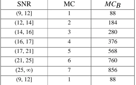
The OFDMA transmission has been applied by using 192 data subcarriers, 8 pilots, 256-point fast Fourier transform block, and a variable cyclic prefix length and bandwidth. Binary phase-shift keying (BPSK), quadrature phase-shift keying (QPSK) and quadrature amplitude modulation (QAM) are used within the OFDM. Coding has been run as Forward Error Correction (FEC), consisting of a Reed- Solomon (RS) outer code concatenated with a rate- compatible inner convolutional code (CC). The applied modulation and coding has been split into seven MC groups (BPSK ½, QPSK ½, QPSK ¾, 16QAM ½, 16QAM ¾, 64QAM ⅔ and 64QAM ¾). After modulation each fraction denotes overall coding rate (uncoded to coded block size ratio). SNR levels, shown in Table 1, have been used to determine whether the subcarriers belong to a particular MC group. SNR thresholds are set for each MC group based on the required bit error rate (BER).
The row MCB in Table 1, shows how many bits can be sent per one subcarrier in one frame by using a specified MC group.
Table 1. MC groups parameters
SNR MC MCB
(9, 12] 1 88
(12, 14] 2 184
(14, 16] 3 280
(16, 17] 4 376
(17, 21] 5 568
(21, 25] 6 760
(25, ∞) 7 856
Published Vol. 1 Issue 4 2016
DOI: 10.18535/etj/v1i4.01
ETJ 2016, 1, 87-94
89The SNR values are calculated directly from the preambles. Each frame starts with the preambles that are a basis for channel transmission function and SNR-values calculation for subcarriers in the next frame. The downlink for three users with three independent transmission channels has been designed. A nonfading, flat-fading, or dispersive multipath fading channel can be chosen in each channel. Additive white Gaussian noise (AWGN) variance (in SNR mode) has been added to the signal. An appropriate K factor, maximum Doppler shift, path number, and path gains can be changed accordingly. The data rate varies dynamically in relation to the channel conditions.
Stanford University Interim (SUI), SUI 3 channel model has been used in the simulation, together with the following parameters: dispersive multipath fading channel with different combinations of AWGN parameter, K factor 0.5, maximum Doppler shift 0.5 Hz, delay vector [0 0.4 0.9] in µs
and gain vector [0 -5 -10] in dB.
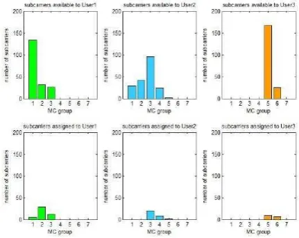
3. PROPOSED SCHEDULING
The proposed RAA is a two-phase algorithm. Figure 1 shows subcarrier selection procedure for each user. The upper row shows available subcarriers for assignment, while the lower row illustrates the assigned subcarriers to each user. The picture depicts that the user 3 achieves best conditions in the transmission channel and their subcarriers belong to the highest MC group. At the same time user 1 has the worst conditions in the channel and the lowest MC group. The assignment process starts from the best and ends with the worst subcarriers. The incoming data contain RT and NRT data traffic. In the first phase the algorithm allocates RT and, if defined, mandatory NRT (mNRT) data traffic. The resources for mNRT data have been allocated to ensure that all users get minimum guaranteed bandwidth for NRT data traffic [9]. In the second phase NRT data traffic is joined to their subcarriers up to the full system capacity. Due to stricter QoS requirements for RT traffic, the subcarriers with the best SNR values are selected first for each user separately. The assignment of better quality subcarriers to RT traffic guarantees the satisfaction of QoS requirements. In this way the entire system capacity has been enhanced and the required QoS parameters like small delay, delay variation, and maximum sustained data rate have been achieved [10].
Figure 1. A sample of available and assigned subcarriers to the users in a frame
The weight factors (W) are direct measures of transmission capacity allotted to the users. They are expressed in allocated bits’ number for useful data transmission in the observed time period within the frame [11]. Fair resource allocation has been achieved by equalizing Ws, while data rate maximization is accomplished by selecting the best subcarriers for each user.
Published Vol. 1 Issue 4 2016
DOI: 10.18535/etj/v1i4.01
ETJ 2016, 1, 87-94
90Ws and MC groups are the same, allocation of the same subcarriers from the previous allocation cycle to
the same users is avoided as much as possible. Thereby the effect of FH is created [12].
The applied algorithm assigns a subcarrier Xk, (k = 1, 2, ..., M), where M is the number of data
subcarriers) to the user Uj, (j = 1, 2, ..., N, where N is number of users). The logic of the algorithm is
described as follows:
1. it is determined how many users h from N fulfills the following two conditions:
a user has data for transmission
a user has free and usable subcarriers
2. if h = 0, the algorithm stops
3. if h = 1, subcarriers are allocated to the targeted user for data transmission until there are either free
subcarriers or data
4. if h ≥ 2, subcarriers are assigned according to the following rules:
To assign a subcarrier Xk, to the user Uj, the user
Uj has to have the smallest W:
Wj minW1 ,...,WN
W1, ..., WN, are weight factors for users U1, ..., UN. Subcarriers are allocated to this user until the upper condition is valid. After that the algorithm starts from the beginning.
If there are more users with the same factor W, subcarrier Xk would be allotted to the user Uj provided
that Xk has the highest MC group for user Uj:
G( X k ) max
G( X 1 ),....,G( X M )
Function G(X) determines which MC group is assigned to subcarriers Xk. MC groups are allotted according to Table 1. Additional conditions of subcarriers’ allocation that enable LTE systems are:
o if users have the same MC group and different subcarriers, a subcarrier is allotted to the first
registered user in the system provided that the same subcarrier has not been allotted to this user in the previous allocation cycle. If the decision has not been made, it is checked whether there are additional subcarriers with the same MC group. If the latter are available, the subsequent subcarrier has been taken and previous allocation cycle is checked to avoid repetitive allocation of the same subcarrier to the same user. If the decision on subcarrier allocation has still not been made, a
subcarrier is added according to the registrationorder in the system;
o if users have the same MC group and the same subcarriers, the previous allocation cycle has been
examined. The subcarrier is allotted to the user whom it has not been assigned to in the previous allocation cycle.
4. SIMULATION RESULTS
To test efficiency of the proposed RAA the system needs to be overloaded. With little system load the applied RAA cannot show its full functionality because the algorithm is not crucial for subcarrier allocation.
Minimum bit quantity that needs to be transmitted in each data downlink frame is defined for RT traffic to fulfill QoS requirements for this data class. If this condition has not been satisfied, the simulation stops. It is possible to define minimum quantity of NRT traffic (mNRT) that needs to be transmitted in each frame. The quantity of remaining NRT
Published Vol. 1 Issue 4 2016
DOI: 10.18535/etj/v1i4.01
ETJ 2016, 1, 87-94
91a buffer to be transferred in the next frames.
The data transfer for three users is simulated in the model. . Three users are chosen due to
presentation simplicity reasons. If the conditions in the transmission channel between various users are the same, fair allocation of total system capacity is assumed.
Hence, fair resource allocation and system capacity with different channel quality are observed in the proposed, WF and PF methods [13].
4.1 System throughput calculation
The system throughput has been calculated according to the following expressions. Assume Zi is the number
of subcarriers of certain MC group. The variable MC denotes MC group, i = 1, 2, ..., 7.
M
Z
i
1
MC i
1
MC I 1, MC i
0, MC i
Transmission system capacity C assigned to the user Uj is calculated as the number of bits that a user Uj,
can transfer in one frame
7
CU j =
Z
ij *MC
BiM=1
U
j .MC
BiZji is the number of subcarriers of certain MC group for user Uj.MCBi , i = 1, 2, ..., 7 is the number of bits
transferred by certain MC group according to the Table 1.
The system transmission capacity of the frame is calculated as: N
C
FRAME
CU jm1
If M =192, N=3, in the simulation sample transmission capacity of one frame equals:
3 3 7
C
FRAME
CU j =
Z jiMC
Bij 1 j=1 i-1
3 7 192
(
1 MC=,I,j
)
MCBi j 1 i-1 m=1
If FT denotes the duration of one frame, throughput TR is obtained according to the formula:
Published Vol. 1 Issue 4 2016
DOI: 10.18535/etj/v1i4.01
ETJ 2016, 1, 87-94
92TR = CFRAME
FT
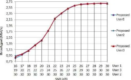
4.2 Resource allocation among users in the proposed, WF and PF methods
Resource allocation for the proposed method with different SNR values in users’ transmission channels in presented in Figure 2.
The comparison has been done on the basis of 10 frames and full system load. For the algorithm presentation purpose, the incoming data contain NRT traffic only. In This way the resource allocation to users is easily comparable. Due to simulating great differences in quality of the transmission channel between the users, average SNR values are set to 16, 19 and 30.
After the proposed algorithm has been applied, the subcarrier allocation is even in the wide bandwidth except at the lower SNR values. There are slight differences in assigned capacities to the users that the system cannot compensate for due to data rate maximization rule. The SNR value of 16 is taken because the quality of transmission channel worsens significantly below this threshold while BER falls below the defined 10-5 value. Reduction of differences in the transmission system channel quality contributes to equalization of the assigned capacity among the users.
Figure 2. Resource allocation for the proposed method
Proportional subcarrier allocation has been done with the PF method. Every third subcarrier has been allotted to each user. MC group has been selected based on the SNR value calculation for each subcarrier. As illustrated in Figure 3, fair resource allocation between users in PF method depends exclusively on the quality of assigned subcarriers
Figure 3. Resource allocation for the proportional fairness method .
Published Vol. 1 Issue 4 2016
DOI: 10.18535/etj/v1i4.01
ETJ 2016, 1, 87-94
9327 30 30). SNR and apportioned MC group are selected just like in the previously described methods.
Figure 4. Resource allocation for water filling method
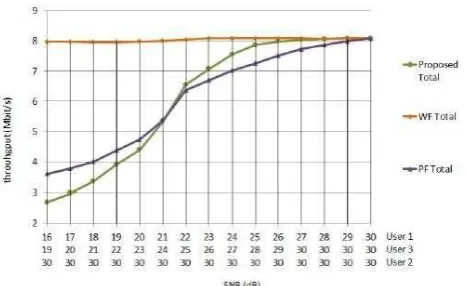
4.2 System throughput for the proposed, PF and WF methods LTE systems
Total system throughput for three users is compared by applying the proposed, WF and PF method as it is shown in Fig. 5. WF ensures maximum system capacity all the time but with disproportional resource allocation between the users. PF provides higher system throughput compared to the proposed method at lower SNR values but with worse and disproportionate resource allocation between the users. The proposed method shows smaller system capacity at lower SNR values because the resources are taken from the users with better SNR values and allotted to users with worse SNR. From mid (21 24 30) to higher SNR values the proposed method is better than the PF and WF method either in resource allocation or in overall system capacity.
Figure 5. System throughput for the proposed, water filling and proportional fairness algorithm
CONCLUSION
The developed resource allocation algorithm primarily provides fair resource LTE OFDM allocation among users, taking care of transmission system throughput. It dynamically selects the best available subcarriers to each user based on the channel quality information.
Resource allocation and system throughput are compared for the proposed method, WF and PF algorithm at different SNR levels in users’ transmission channels. The proposed method ensures fair resource allocation between users in wider SNR area with varying conditions in the transmission channel. However, greater fairness in resource allocation causes smaller total system capacity at lower SNR values. these results are in agreement with 3GPP proposal .
Published Vol. 1 Issue 4 2016
DOI: 10.18535/etj/v1i4.01
ETJ 2016, 1, 87-94
94Future research work on this method should concentrate on reducing the need for additional control information transmission.
Due to interrelation between the achieved throughput and MC groups’ thresholds, one of the tasks is introducing dynamic instead of static thresholds based on the transmission channel behavior.
REFERENCES
1. Xenakis, D., Tsolkas, N., Passas, N., Alonistioti, N., and Merakos, L. 2012. Dynamic resource
allocation in adaptive wireless OFDMA systems. Wireless Communications and Mobile
Computing. 12, 11 (Aug 2012), 985-998. DOI=10.1002/wcm.1030.
2. Ali-Yahia, T., Beylot, A.-L., and Pujolle, G. 2007. Radio resource allocation in mobile WIMAX
networks using service flows. In Proceedings of the 18th IEEE Symposium on Personal, Indoor
and Mobile Radio Communications (Athens, Greece, 3-7 Sept 2007). 1-5.
DOI=10.1109/PIMRC.2007.4394437.
3. IEEE Standard for Local and Metropolitan Area Networks,Part 16: Air interface for broadband
wireless access systems. Std. 802.16 - revision of IEEE Std. 802.16-2004. 2009. IEEE, New York, USA
4. Ali-Yahiya, T., Beylot, A.-L., and Pujolle, G. 2008. Crosslayer multiservice scheduling for
mobile WiMAX systems.In Proceedings of the IEEE Wireless Communications and Networking
Conference (Las Vegas, USA, 31 March – 3 April 2008). 1531-1535. DOI=
10.1109/WCNC.2008.274.
5. Borin, J. F. and Da Fonseca, N. L. S. 2008. Scheduler for IEEE 802.16 Networks. IEEE
Communications Letters. 12, 4 (April 2008), 274-276. DOI= 10.1109/LCOMM.2008.072110.
6. Nguyen, T.-D. and Han, Y. 2006. A proportional fairness algorithm with QoS provision in
downlink OFDMA systems. IEEE Communications Letters. 10, 11 (Nov 2006), 760-762. DOI=
10.1109/LCOMM.2006.060750.
7. Frimis, I. G. and Kotsopoulos, S. A. 2011. QoS-Based proportional fair allocation algorithm for
OFDMA wireless cellular systems. IEEE
8. Communications Letters. 15, 10 (Oct 2011), 1091-1093. DOI=
10.1109/LCOMM.2011.081211.111417.
9. Cho, Y. S., Kim, J., Yang, W. Y., and Kang, C. G. 2010. MIMO- OFDM Wireless
Communications with MATLAB. IEEE Press & John Wiley and Sons (Asia) PTE Ltd, Singapore.
10.Alavi, S. M., Zhou, C., and Cheng, Y. 2009. Low complexity resource allocation algorithm for
IEEE 802.16 OFDMA system. In Proceedings of the IEEE ICC (Dresden, Germany, 14-18 Jun
2009). 1-5. DOI= 10.1109/ICC.2009.5199154.
11.Wu, T.-M. and Wang S.-L. 2007. Dynamic and fair resource allocation algorithm for OFDM
systems. IEEECommunications Letters. 11, 12 (Dec 2007), 931-933. DOI=
10.1109/LCOMM.2007.071245.
12.Farrokh, F. R., Olfat, M., Alasti, M., and Liu, K. J. R. 2004. Scheduling algorithms for Quality
of Service aware OFDMA wireless systems. In Proceedings of the IEEE GLOBECOM
(Dresden, Germany, 29 Nov – 3 Dec 2004). 4, 2689-2693. DOI=
10.1109/GLOCOM.2004.1378493.
13.Putzke M. and Wietfeld, C. 2011. Self-organizing OFDMA systems by random frequency
hopping. In Proceedings of the 4th IFIP Wireless Days Conference (Niagara Falls, Ontario,
Canada, 10-12 Oct 2011). 1-6. DOI=10.1109/WD.2011.6098175.
14.Marabissi, D., Tarchi, D., Fantacci, R., and Biagioni, A. 2008. Adaptive subcarrier allocation
algorithms in wireless OFDMA systems. In Proceedings of the IEEE ICC (Beijing, China, 19-23