http: // www.ijrtsm.com© International Journal of Recent Technology Science & Management 10
ISSN : 2455-9679
[Sunil et al. , 3(5), May 2018 Impact Factor : 2.865
IJRTSM
INTERNATIONAL JOURNAL OF RECENT TECHNOLOGY SCIENCE & MANAGEMENT
“Design and Optimization of Perfect Gating System for Uniform Solidification
Rate of Given Component
”
Sunil Yadav
1,
Vaibhav Jain
2,Vikas Sharma
3Krishna Waghe
41,PG, Scholar, Dept. of Mechanical Engineering, MIT, Indore, MP, India
2,3Assistant Professor, Dept. of Mechanical Engineering, MIT, Indore, MP, India
ABSTRACT
The main purpose of today’s manufacturing industries is to produce low cost, high quality products in short time. Casting is manufacturing process in which component of machine made by solidification of molten metal in a specific cavity to form a predesigned shape. There are so many parameter are involve in casting process like allowances, surface finish and defects in component. This all effects are controlled by achieving uniform solidification rate throughout the process. For this uniform solidification a proper method of casting and gating should be designed. So in this research work a large sized component is designed, analyzed and manufactured through lost foaming casting process for zero drafting allowances and minimum machining allowances with best surface finish.
Keyword: Sand, Pattern, Casting, Cavity, Mold, LFCP
I.
I
NTRODUCTIONAs I reviwed the effect of defferent methods of casting in my previous paper [4] and find a appropriate method of casting which is Lost Foam casting will be best suitated for large sized component ccasting. In this Lost foam casting technique (LFC) is known by different generic and propriety names like lost foam, evaporative pattern casting, evaporative foam casting, full mold, etc. Similar to the full
mold process, in this process the pattern evaporates when the metal is poured into the mold. Lost foam casting is a type of metal casting process that uses expendable foam patterns to produce castings. Expanded polystyrene foam is used which melts when molten metal is poured into the mold.
Application: Lost foam casting is used mostly for automotive
applications. Cast iron, aluminumalloys, steels, nickel and in some cases stainless steel and copper alloys are cast in this process. The flexibility of LFC is useful in making complicated casting assemblies for automotive parts like cylinder heads, weldments etc. This simple and inexpensive method is used in hobby foundry work.
http: // www.ijrtsm.com© International Journal of Recent Technology Science & Management 11
ISSN : 2455-9679
[Sunil et al. , 3(5), May 2018 Impact Factor : 2.865
II.
OBJJECTIVE OF WORKThe objective of research work is to produce low cost, high quality products in short time using latest technologies like ProCAST analysis software. In casting process suitable method and design are responsible for perfect casting of component. But for testing alternative design by manufacturing it’s taking time and lots of money, so instead of manufacture for each time we can use casting analysis software and test over it and find the optimum solustion which reduces wastage of Material, time and money for such large sized component. Once the design is functionined properly on software then only we manufactured physicaly.
So objective of this project is to design and optimize casting through computer and then manufacture component physically. The specification of component is mentioned in figure 2.1 below.
III.
METHEDOLOGYMethodology for project as follows
Figure2.1 Large Sized Casting Bed
http: // www.ijrtsm.com© International Journal of Recent Technology Science & Management 12
ISSN : 2455-9679
[Sunil et al. , 3(5), May 2018 Impact Factor : 2.865
IV.
DESIGN CALCULATIONS4.1 Bed Plate size (6000 X 2000 X 250 mm)
Pouring Time (t)
Casting weight less than 450 kg (1000 Ibs)
Sec
Where
K= Fluidity factor dependent on equivalent carbon T= Average casting thickness (inches)
w= Weight of casting (Ibs), (maximum 450 kg or 1000 Ibs) for 4.0 eq. carbon, K=0.85 to be taken
T= 3.2 inches
w=11270 kg (24846.09 lb)
4.2 Rate of rise of metal:
Height of Casting h=271 mm
Note: Rate of rise of metal should be
● 6-10 mm/sec for wall thickness of 40mm or more
● 10-20 mm/sec for 10-40 mm wall thickness
● In Jash Engineering Limited(for gate) taken 6mm/sec
4.3 Pouring Rate
It is denoted by “R”
4.4 Mean Effective Head
● For top gating : Hst =H
● For bottom gating : Hst =H-(C/2)
● For parting line gating: Hst =H-(P
2 /2C)
Where,
H = Head of Metal in Sprue C = Height of Casting
P = Distance between gate and top of the Casting H =height of casting + height of moulding box H=271+200 = 471 mm
Hst =H-(C/2)
Hst =471-(271/2)
Hst =335.5 mm (33.55 cm)
4.5 Choke Area
Where,
http: // www.ijrtsm.com© International Journal of Recent Technology Science & Management 13
ISSN : 2455-9679
[Sunil et al. , 3(5), May 2018 Impact Factor : 2.865
T = Pouring time (Sec)
D = Density of molten metal (kg/mm3)
g = Acceleration due to gravity (mm/sec) H = Effective metal height (sprue height in mm)
C = Effective factor which is a function of gating system used (friction factor = 0.83)
4.6 Total Gate Area It is denoted by Ag
Where,
R = Pouring rate (kg/sec)
Hst = Mean effective head (cm)
μ = Velocity loss Coefficient Note:
µ = 0.4 for high loss CO2 mould , complicated gating system
µ = 0.5 for green sand casting
µ = 0.6 for short gating system, dry sand moulds
4.7 Cross-sectional area of each gate
Width : Thickness = 4 : 1
For grey iron castings, the thickness of gate will depend on the pouring temperature of metal
Gate should be connected at the thinnest section of the casting. Gate length(runner to casting) : 1-2 times the gate width Branch off gate from the runner at right angle
Width : Thickness = 4 : 1 =25 :10 (40mm x 12mm) modified
4.8 Cross-sectional area of runner
Runner Area = 2.25 times Total Gate Area Note:
● Shorter runner requires large area of cross-section, longer area may have smaller cross-section
area.
● Design the runner cross-section so that the height is 2-3 times of width.
● Bottom of both- the runner and the gate(s)-may be located in the cope. If the gate should be in drag part of
runner (equal to depth of the gate) should also be in the drag.
Sr. no
Pouring Temperature
Gate Thickness
1 14800C 3 mm
2 13800C 6 mm
3 13150C 12 mm
http: // www.ijrtsm.com© International Journal of Recent Technology Science & Management 14
ISSN : 2455-9679
[Sunil et al. , 3(5), May 2018 Impact Factor : 2.865
Runner Area = 2.25 x 71.95
= 161.88 cm2
= 16188 mm2
= 16188/3 = 5396 mm2
Wxh = 60x90 = 5400 mm2
4.9 The sprue bottom area and diameter Area-diameter of sprue
bottom = 1.33Ag =1.33 x 71.95
= 95.69 cm2
(Circular sprue is preferred), Area of circle
A = πr2
A = 3.14 x r2
95.69 = 3.14 x r2
r2 = 95.69/3.14 = 30.46
r = 5.52 cm = 55 mm
4.10 The sprue top area and diameter
Area of sprue at pouring basin = (sprue area at the bottom)x µc x (Hs/Hp)
Where ,
µc = 0.7
Hs = Height of sprue
Hp = Height of pouring basin
For short sprue : Area of sprue at top = 2 x Area at bottom of sprue Diameter at pouring basin is 1.5 to 2 times of sprue at bottom side
= 1.5 x 55 = 82.5 mm Top Diameter = 82 mm
4.11 The dimension of sprue base
Diameter of sprue base = 2x(diameter of sprue bottom) Height of base = Height of runner
4.12 Dimensions of pouring basin
Capacity of pouring basin (kg) = K x R
Where,
K = constant (7.5 for casting upto 1500 kg and 6.0 for casting above 1500 kg) R = Pouring rate (kg/sec)
Capacity of pouring basin (kg) = K x R
= 6 x 208.317 = 1249.9 kg
For no. of sprue 1 L=1.5=600 mm =0.6 m W =1=400 mm =0.4 m H=0.7=230 mm= 0.23 m
Volume = L x W x H = 0.6 x 0.4 x 0.23 = 0.0552m3
Total Mass = 0.0552 x 7300 = 402.96 kg
V
.
ANALYSIS OF GATING SYSTEM USING PROCAST
5.4 Gate Design
3D model has been prepared for Pattern casting machine using CAD modeling software, Creo. A Two gate-bed plate model has been modeled first.
No. of Sprue L W H
1 1.5 1 0.7
2 1.6 1 0.7
http: // www.ijrtsm.com© International Journal of Recent Technology Science & Management 15
ISSN : 2455-9679
[Sunil et al. , 3(5), May 2018 Impact Factor : 2.865
Figure 5.1: Two Gated-bed Plate model
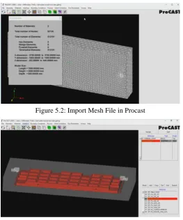
Figure 5.2: Import Mesh File in Procast Figure 5.3: Mesh Mould
Figure 5.4: Casting material Selection FEGG25 Figure 5.5: Mould material Selection As green Sand
http: // www.ijrtsm.com© International Journal of Recent Technology Science & Management 16
ISSN : 2455-9679
[Sunil et al. , 3(5), May 2018 Impact Factor : 2.865
While we observe solidification rate in two gate system we find that a metal is not solidify uniformaly and a large are is left that cause scaling defect in casting. And due to this a machining allowance needed. So now we need to optimize gating system for uniform solidification.
VI
.
OPTIMIZATION OF GATING SYSTEM
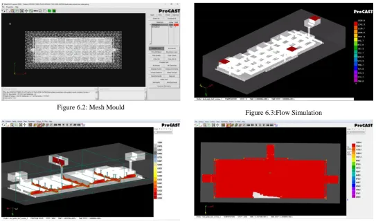
As we discussed about solidification rate is how much important for low cost high quality & less Time consuming casting, so in order to obtain uniform solidification rate we need to optimize gatting system now we design a three gate mould and analys on proCAST.
Figure 5.1: Three Gated-bed Plate model
Figure 6.2: Mesh Mould
Figure 6.3:Flow Simulation
http: // www.ijrtsm.com© International Journal of Recent Technology Science & Management 17
ISSN : 2455-9679
[Sunil et al. , 3(5), May 2018 Impact Factor : 2.865
VII
.
RESULT & DISCUSSION
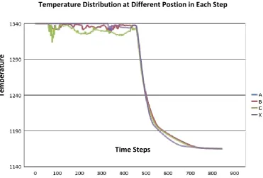
As we analysized both type of gatting system we get the good results in Three gate system. ProCast also give Temperature distribution at each steps. For using this temperature changes mentioned in Figure 7.1 and Figure 7.2 we can understand the rate of solidification.
Figure 7.1: Temperature Distribution & Soldification for Two Gate System
Time Steps
Te
mpe
ra
tu
re
Temperature Distribution at Different Postion in Each Step
Time Steps
Te
mpe
ra
tu
re
Temperature Distribution at Different Postion in Each Step
http: // www.ijrtsm.com© International Journal of Recent Technology Science & Management 18
ISSN : 2455-9679
[Sunil et al. , 3(5), May 2018 Impact Factor : 2.865
VIII
.
CONCLUSION & FUTURE SCOPE
8.1 Conclusion:
In Results It has been clear that in three gate system temperature curves are close to each other which shows that solidification are uniform and also the casting simulation technology has become an essential tool for casting defect troubleshooting and optimization method. It improves quality product without shop-floor trials.With the use of optimization techniques gating system of the casting are improve and increase the yield percentage of the casting. This would result reduction in cost and material saving. Many design rules, are developed over the years through experience and study. But For wide spread application, simulation programs must be easy to use, fast, and reliable. This can been achieved by integrating method design, solid modeling, simulation techniques. The Simulation software has proven its reliability and accuracy in predicting internal defects which help to reduced shop floor trials, and optimization using a single software program.
8.2 Future Scope:
Advanced lost foam casting processes (Pressure Assisted Solidification and Vacuum Assisted Mold Filling) have demonstrated the capability to improve mechanical properties, especially fatigue performance, for aluminum alloys and improve casting cleanliness, which reduces scrap, for ferrous alloys.Advantages of LFCP that have not been fully utilized are
1) freedom from gray iron “skin” formation in ductile and compacted graphite iron and 2) elimination of hot tearing for high strength, cast aluminum alloys.
So in Future Pressure Assisted Solidification and Vacuum Assisted Mold Filling can be used to Improve results
REFERENCES
1. Rupinder Singh, Sunpreet Singh, Gurpartap Singh,“Comparison of Investment Castings Prepared With Wax and
ABS Patterns.” 3rd International Conference on Materials Processing and Characterisation (ICMPC 2014), Procedia Materials Science 6, 2014, 851 – 858.
2. Rupinder Singh, Sunpreet Singh, Vishal Mahajan, “Investigations for Dimensional Accuracy of Investment
Casting Process after Cycle Time Reduction by Advancements in Shell Moulding.” 3rd International Conference on Materials Processing and Characterisation (ICMPC 2014), Procedia Materials Science 6 (2014) 859 – 865
3. Sunil Yadav, Vaibhav Jain “Alternative Casting Methods for Large Sized Component over Sand Casting
Methods: A Review” International Journal of Recent Technology Science & Management (IJRTSM) Vol.3, Issue-3, March 2018, pp 19-24
4. D.Caulk "Analysis of Mold Filling in Lost Foam Casting of Aluminum",International Journal of Metalcasting,
January 2009, Volume 3, Issue 1, pp 7–25.
5. M. khodai, S.M.H. Mirbagheri, "Behavior of Generated Gas in Lost Foam Casting.", International Journal of
Materials and Metallurgical Engineering Vol:5, No:2, 2011 Pp 151-155.
6. S. Shivkumar, “Modeling of temperature losses in liquid metal during casting formation in expendable pattern
casting process”, Vol. 10, Materials Science and Technology, 1994, PP. 986-992.
7.
Helder Pinto, F. J. G. Silva,“Optimisation of die casting process in Zamak alloys.” 27th International
Conference on Flexible Automation and Intelligent Manufacturing, FAIM2017, 27-30 June 2017,
Modena, Italy, Procedia Manufacturing 11, 2017, 517 – 525.
8. Bhupendra j. Chudasama "Solidification Analysis and Optimization Using Pro-Cast" International Journal of
Research in Modern Engineering and Emerging Technology (IJRMEET) ISSN: 2320-6586 Vol.1, Issue 4,
May13, pp 9-19.
9. Ravi, B. (2000). Computer Aided Design And Analysis For Zero Defects, International Conference on
Aluminium,p. 1-6.
10. Rabindra Behera, Kayal, S. Sutradhar. G. (2001). "Solidfication behaviour and detection of Hotspots in
Aluminium Alloy castings: Computer Aided Analysis and experimental validation",International Journal of