Copyright © 2015 IJECCE, All right reserved
Unbalanced Magnetic Force Calculation in Brushless
DC Motors
Z. Valipoor
Malek-Ashtar University of Technology Department of Electrical and Avionics
Engineering, Isfahan, Iran email: Z.valipoor990@gmail.com
M. Jafarboland
Malek-Ashtar University of Technology Department of Electrical and Avionics
Engineering, Isfahan, Iran email: J_mehrdad405@hotmail.com
Farid Salehi Nia
Shahid Chamran Research Center Ashtar University of Technology,Esfahan, Iran
email: Fsalehinia1989@gmail.com
J. Shishegar
Malek-Ashtar University of Technology Department of Electrical and Avionics Engineering,
Isfahan, Iran
email: Jafar.shishegar@iaukhsh.ac.ir
M. M. Sargazi
Malek-Ashtar University of Technology Department of Electrical and Avionics Engineering,
Isfahan, Iran email: mms.mut@gmail.com
Abstract: In this paper, an analytical method to calculate the unbalance magnetic pull forces (UMP) due to the eccentricity of the rotor with considering the slots impact, is presented. Unbalanced magnetic pull is important because it affects the wear on the bearings as well as noise and vibration. The results of the analytical method, using finite element analysis for a prototype motor, were valid. Some force harmonics have the potential to produce noise and vibration. In order to detect harmonics of unbalance magnet forces, Depending on the fault frequency, the stator currents and spectrum of the vibrations have been analyzed.
Keywords: Noise and Vibration, Unbalance Magnetic Forces, Eccentricity, Spectrum Analysis.
I.
I
NTRODUCTIONBrushless dc motors due to their many advantages, are widely used in many applications and industrial fields, while they are alternative source of vibration and acoustic noise. Vibration and noise in electrical machines are directly related to the characteristics of the radial forces on one hand, and the mechanical behavior on the other. The characteristics of these forces depend on the air gap flux density, which is also influenced by other factors, such as stator slots and poles, saturation level, winding type, and certain faults. When a rotor exits from the center of the stator, a net radial force will be generated. This force pulls the rotor off centre leading to an asymmetric load on the bearings. Such a force is referred to as unbalanced magnetic pull (UMP) [2].
Rotor eccentricity in electrical machines can be induced for many reasons. Manufacturing tolerance, which differs in cost, leads to a decrease in the uniformity of the air gap. The effect of eccentricity is introduced through the expression of the relative permeability.
In this paper, an analytical model has been developed
to calculate the unbalanced magnetic pull due to rotor eccentricity. The model has been verified with 2D electromagnetic finite element analysis. Also, the harmonics of the UMP have been detected in the typical motor using current and vibration spectrum and it has been discussed about analysis.
II.
R
OTORE
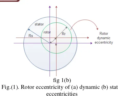
CCENTRICITYGenerally, in an ideal machine, the rotor is located in the center of the stator while they are aligned with each other and originally rotor and stator are concentric. In this case, the attractive force between the rotor and stator are equal and in an act, so the resultant force is zero. When air gap between the stator and rotor be asymmetric, the rotor eccentricity occurs. The rotor eccentricity in a motor can be divided into three categories: static eccentricity, dynamic eccentricity and their combination. In static eccentricity, the rotor is displaced from the center of stator, but also rotates on its axis.
In this case, minimum of radial air gap length is fixed in the space. In dynamic eccentricity, rotor is not in the center of itself and rotates at the center of the stator. In this case, the minimum of air gap rotates with rotor. So, dynamic eccentricity is a function of the position and time. The static eccentricity causes unacceptable level of UMP in one direction, which its result is bent shaft and finally dynamic eccentricity. Both of them cause to wear of the bearings and damaging vibrations.
Figure 1 displays rotor eccentricity,
Copyright © 2015 IJECCE, All right reserved fig 1(b)
Fig.(1). Rotor eccentricity of (a) dynamic (b) static eccentricities
III
.
C
ALCULATION OFU
NBALANCEDM
AGNETICP
ULLSThe unbalance magnetic pulls can be divided into two types;may be an external source, such as incorrect assembly, asymmetric magnetic rings magnetizing, and incorrect dimensions of the stator core. The second type of the UMP is an inherent source of the electromagnetic structure of the motor that can be calculated considering the poles of the magnet or even the number of slots.
For cylindrical objects, such as the rotor of a generator, radial direction Maxwell Stress Tensor can be expressed as:
0 2 2
2
n tr
b
b
(1)That n is the normal magnetic flux density, t is the tangential magnetic flux density in the air-gap and, μ0 is vacuum permeability. The tangential component is conventionally negligible.
The total radial magnetic force applied on the rotor of a generator is given by,
d
t
b
L
F
nr
2 0 0 2
2
)
,
(
(2)When the rotor is perfectly concentric, this force can be neglected. With rotor eccentricity, a considerable UMP force will be induced [2].
4.
A
NALYSISM
ETHODAssuming the rotor is cylindrical and sufficiently rigid, so the variations in the air gap length under running condition will be negligible. Then in both cases, static and dynamic eccentricity, the expression of
variable air gap can be obtained from the following equation: g e g e g t g / )) cos( 1 ( ) cos( ) , ( (3)
Where, �, �, �� are the relative eccentricity, the rotor position and the length of the air gap in the state are being concentric, respectively.
The permeability coefficient, that is the inverse of the air gap, using Fourier series shown in equation (4).
n is the common factor of Fourier series of the perme- ability of air gap function:2 2 ,.. 2 , 1
1
)
1
1
(
2
)
cos(
)
,
(
1
)
,
(
n n n n nn
t
g
t
(4)By assuming value one for the magnetic permeability coefficient, Fourier series of the radial flux density for interior and outer magnet rotor of BLDC motors can be expressed as:
,
t
=
B
.
cos(
)
B
1,3,... n
n
r
np
(5)
That �� for the interior rotor magnet expressed as[6]:
] ) ( ) ( ) [( ]. ) ) ( 1 ( * 2 ) )( 1 ( ) ( 2 ) 1 ( [ 1 ) ( . 2 / ) 2 / sin( 2.B B 1 1 1 2 2 1 2 r n np r m np s m np s r np r np m r np m r p p R R R R R R Rs R R R np R R np np np np np
(6)And for outer rotor magnet is[6]:
Copyright © 2015 IJECCE, All right reserved That :
g
R
R
Outer
g
R
R
s m
s m
:
:
Interior
(8)
The general equation to calculate the radial magnetic pull expressed as[4]:
0 2 2
0 2
2
)
,
(
).
,
(
2
t
B
t
B
F
rr
(9)The radial magnetic pull was obtained for fundamental component of flux density for substituting in equation (9), and integration from equation (10) along the axis of the motor, the UMP forces obtained as follows:
]
)
1
(
cos
)
1
cos(
.
)
1
cos(
2
)
1
(
[cos
)
1
(
)
1
1
(
.
8
2 2
2 2 2 2
1 0 1
p
p
p
p
B
F
r(10)
)
1
(
)
1
1
(
.
.
8
.
.
.
2
22 2 2
1 0
2
0
B
L
d
F
L
Ump
r(11)
5.
M
OTORE
XAMPLE ANDF
INITEE
LEMENTA
NALYSISFor a typical interior magnet rotor with the following characteristics in Table 1, the results of analytical calculations is obtained and compared with FEA.
Table (1). Characteristics of motor interior rotor magnet
Parameters value Parameters value
Number
of pole 4
Residual flux density
of PM(Tesla)
1.23
Number of slot 24
Outer diameter of stator(mm)
51
Speed(rpm) 1497
Outer diameter of
rotor(mm) 60
Rotation
frequency(hz) 49.9
Air gap
Length(mm) 0.5 Stake
length(mm) 77
relative
eccentricity 0.1
Figure 1, show the design of the motor in the Maxwell. Can see the flux density distribution in different parts of Interior rotor magnet.
Fig.(1). Flux density distribution in different parts of Interior rotor magnet
Considering the amount of 0.1 for the relative eccentricity (�), as can be seen in figures 2 and 3, the results of the analysis calculation and finite element analysis.
Fig (2). Radial magnetic pull waveform using analytical calculation
Fig.(3). Radial magnetic pull waveform using FEA
0.00 100.00 200.00 300.00 400.00 500.00 600.00 Moving1.Position [deg]
1.40 1.45 1.50 1.55 1.60 1.65 1.70
F
o
rce
1
.F
o
rce
_
ma
g
[
kN
e
w
to
n
]
Maxwell2DDesign11
XY Plot 4 ANSOFT
Copyright © 2015 IJECCE, All right reserved The results of the analysis calculation and finite
element analysis, have a similar shape and amplitude. In both cases, the average amount of unbalanced force is 1.5*10^3 Newton. The comparison of results implies the validity of the obtained formula.
The comparison of the output torque is presented in two modes (with eccentricity and without eccentricity) in figure 4. Output torque with rotor eccentricity decreased and its ripple increased.
Fig.(4). Comparison of output torque with and without rotor eccentricity
6.
T
HEORETICAL ANDE
XPERIMENTALR
ESULTSFrequency components caused by the unbalance forces in the current and vibration spectrum wasobtained by equation (12), this components are dependent on the number of motor poles and usually occur at rotation frequency[6].
e e
de
f
p
k
f
f
2
(12)Where,�, p and k are the main frequency, number of pair poles and any integer, respectively. In this section, the stator current and vibration spectrum of the prototype motor at speed 1497 rpm are obtained. So � is 50Hz. In figure 5, show arrangement for measurement vibration and line current in the BLDC motor.
Fig.(5). Experimental arrangement for measurement vibration and line current in the BLDC motor
As can be seen in the Figures 6 and 7, experimental results show that the defects of the rotor affect mainly the two sidebands of the fundamental frequency at 1/2rd and 3/2rd. The two smaller sidebands at 1/2rd and 3/2rd appear defect frequency of unbalanced.
Fig.(6).Vibration frequency spectrum of tested motor
fig 7(a)
fig 7(b)
Copyright © 2015 IJECCE, All right reserved
7.
C
ONCLUSIONUMP forces are an important factor in motor vibrations and acoustic noise. Therefore, it is important to identify the effects of these forces. In this paper an analytical method has been expressed to calculate UMP forces. In this method, it is assumed that magnet permeability coefficient is one.The obtained results for the interior rotor magnet of the motor, has been compared to finite element analysis results. Using the same results, the analysis has been validated. By comparison of output torque with and without rotor eccentricity shown that the output torque with rotor eccentricity decreased. Also, in this study, harmonic components of UMP forces analyzed for the typical motor using current and vibration spectrum and the two sidebands at 1/2rd and 3/2rd show defect frequency of unbalanced.
R
EFERENCES[1] Ali Rezig, Mohammed Rachid Mekideche and Abdesslem Djerdir, Impact of Eccentricity and Demagnetization Faults on Magnetic Noise Generation in Brushless Permanent Magnet DC Motors, Journal of Electrical Engineering & Technology Vol. 6, No. 3, pp. 356~363,
[2] X. Wang, Q. Li, S. Wang and Q. Li, Analytical calculation of air gap magnetic field distribution and instantaneous characteris-tics of brushless DC motors, IEEE transaction on energy conver-sion, Vol.18, pp425-432, 2003.
[3] G. F Gereis, C. Wang, J. C Lai and N.Ertugrul, Analytical prediction of noise of magnetic origin produced by permanent magnet brushless motors, in Proceedings of electrical machines and drives conference IEMDC 2007, Antalya, Turkish. [4] Z. Q. Zhu, Senior, David Howe, and C. C. Chan, Fellow,
Improved Analytical Model for Predicting the Magnetic Field Distribution in Brushless Permanent-Magnet Machines, IEEE transaction on magnetics, vol. 38, no. 1, JANUARY 2002. [5] Satish Rajagopalan, Wiehan le Roux, Thomas G. Habetler, and
Ronald G. Harley,Dynamic Eccentricity and Demagnetized Rotor Magnet Detection in Trapezoidal Flux (Brushless DC) Motors Operating Under Different Load Conditions, IEEE TRANSACTIONS ON POWER ELECTRONICS, VOL. 22, NO. 5, SEPTEMBER 2007.
[6] L. J. Wu, Z. Q. Zhu, Fellow, IEEE, J. T. Chen, and Z. P. Xia, An Analytical Model of Unbalanced Magnetic Force in Fractional-Slotn Surface-Mounted Permanent Magnet Machines, IEEE TRANSACTIONS ON MAGNETICS, VOL. 46, NO. 7, JULY 2010,2686-2700.
[7] Yao Da, Xiaodong Shi and Mahesh Krishnamurthy, Health Monitoring, Fault Diagnosis and Failure Prognosis Techniques for Brushless Permanent magnet motors, IEEE (2011) 978-1-61284-246-9/11.
[8] S.mahdiun-Rad, Mousav-aghdam, RezaFeyzi, B.Sharifian, Analysis of PM magnetic forces due to rotor eccentricity in BLDC motors, ETASR-Engineering ,technology & applied science research voi.3,NO.4,(2013) 461-466.
[9] C.I.Lee and G.H.Jang, Experimental measurement and simulated verification of the unbalanced magnetic force in brushless dc motors, IEEE transition magnetic, vol44,NO,11, Novem-ber(2008).
[10] S. Rajagopalan, W.leRoux, Thomas G. Habetler, Fellow, Ronald G. Harley, Fellow, Dynamic eccentricity and demagnetized rotor
magnet detection in trapezoidal flux (brushless dc motors) operating under different load conditions, IEEE transition on power electronic.vol 22,NO.5.september (2007) 359-362.


![Production of alginate beads : a project report [i e thesis] presented in partial fulfillment of the requirements for the degree of Master in Food Technology at Massey University, Auckland, New Zealand](data:image/gif;base64,R0lGODlhAQABAIAAAP///wAAACH5BAEAAAAALAAAAAABAAEAAAICRAEAOw==)