2017 2nd International Conference on Computer, Mechatronics and Electronic Engineering (CMEE 2017) ISBN: 978-1-60595-532-2
The Object’s Reconstruction of CT Detection Based on Filtered Back
Projection Algorithm
Jing-bo GONG
1, Xiao-hua HAN
1, Yun-tao MA
1and Shou-kui SI
2,*1
Students’ Brigade, Naval Aviation University, Yantai Shandong, 264001, China 2
School of Basic Sciences for Aviation, Naval Aviation University, Yantai Shandong, 264001, China *Corresponding author
Keywords: CT detection system, Filtered back projection algorithm, Object’s reconstruction.
Abstract. Now the most scholars will use parallel beam projection reconstruction algorithm to study CT inspection system to reduction the object. By using these algorithms, for CT system detect reduction target image is not clear, stellate lines occurs on the projective reconstruction object artifact, leads to the serious distortion. This article mainly focuses on the improvement of the precision in the detection of the CT system. The first image of the CT system we get is the projection of the object, then the projection is processed with a one-dimensional filter by using Matlab, we can get reconstructed projection. The resulting image is more restored and clearer than without processing in a filter. We use this theory to a specific CT system test and the use of the theory methods to rebuild the absorption rate, clear graphics of object, found that the image after filtering is more accurate and clear.
Introduction
The CT detection system [1], which has an important position in the field of medicine, is used to scan the human body with the X-ray beam for a certain thickness of the body, and then the probe receives the x-rays through that level. The probe turns the x-rays into visible light, and the photoelectric converter switches to electrical signals. Then the analog/digital converter is transferred to the computer for processing. The processing of image formation is to divide the selected layer into a number of identical rectangles, which we call body elements. Convert each digital number in the digital matrix to a small square of gray to white. We call that pixel. We arrange the pixels by the matrix, which is the CT image. The X-ray absorption coefficient of each individual element can be calculated by different mathematical methods. When we studied the projection reduction of the CT system, we found that using the normal anti-projection method may obtained large error, the image is Blurred, it is far away from the true object. This is what motivates us to study how to improve the resolution of the original in the CT system. In the study, we find that the one-dimensional filtering [2] method can get more clear image than using normal back projection method of the CT system.
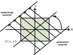
Object Reconstruction Based on Filter Back Projection Method
Model Preparation
'
x
( )'
Rθ x
x y
( , )
[image:2.612.378.517.65.169.2] [image:2.612.110.234.77.171.2]f x y
Figure 1. The transformed image. Figure 2. The detection of figure.
In the common back projection method, there is no object scanning point in the original image, which is the point of zero in the attached table. After the object is rebuilt, it may not be divided into zero, which will distort the image. We call that this star track is introduced to remove the star trails, which can be in a better change on the projection data before projection reconstruction. It is the filtering process.
Finally we utilize the reuse after correcting the value of the projection for projection to get more accurate reconstructions.
Build up of Model. The General anti-projection process [4] is: original drawing, reconstruction from projection and reconstructed image. The vertex in the lower left corner of the square tray is the origin of the axis and the information of projection of the object is in the schedule 3.In this paper, it is referred to as projection information. The attenuation energy value of a point in the detection of a laser cross section can be considered as the mean of the sum of the sum of the radiographic projections of the plane in all angles, which can be expressed as:
, . 1
1
(1)
n
k k i
n
x
p
n
==
∑
Thexkmeans thekpixel value. The
p
k,imeans the i(
180>i>0)
ray projection of the kobject.The attenuation coefficient of the object is f
(
x,y)
and it represents the attenuation coefficient of the object of(
x,y)
, which is the attenuation rate. So when the X-ray scan is the center of rotationR, the projection value in a certain Angle can be expressed as:
(
,
)
(
,
) (
cos
sin
)
.
(2)
P R
θθ
=
∫∫
f x y
µ
x
θ
+
y
θ
−
R dxdy
The re-projection can be expressed as:
(
,
)
(
,
) (
cos
sin
)
.
(3)
b
θx y
P R
θθ µ
x
θ
y
θ
R dR
+∞
−∞
=
∫
+
−
Theµfunction can screen point of view. When we add up all the antiprojections from -60.3 to 118.6 , we can obtain absorption coefficient of image reconstruction.
(
)
(
)
(
) (
)
120 120
60 60
,
,
,
cos
sin
.
(4)
b
f
x y
b
θx y d
θ
d
θ
p
θR
θ µ
x
θ
y
θ
R dR
+∞
− − −∞
=
∫
=
∫
∫
+
−
According to central slice theorem, we can use the Fourier reconstruction to get the back projection.
φ φ r
x
x
y
ry
rx
( r)
pφ x
spatial 1 ω φ 0 0 0 ρ 2 ω ( 1 2)
F ω,ω =Fi (ρ,Φ)
frequency domain
Figure 3. Use the slice theorem to reconstruct the inverse image.
But in the process of reconstruction, we take the radiographic projection from the finite object space evenly to the infinite space where the ray is, so it will include a point where the original pixel value is zero. But the filter back projection method is used to remove these points before the back projection.
The filtering process is carried out in space domain can be expressed as:
( )
{
}
( )
{ }
1 1
1 1 1
.
(5)
F
−
F g
θR
ρ
g
θR
F
−ρ
=
∗
The filter function is selected as:The R—L filter function:
( )
( )
.
(6)
2
R L
H
W
rect
B
ρ
ρ
=
ρ
ρ
=
ρ
—
The image function will be reconstructed can be expressed as:
(
)
(
)
(
)
(
)
( )( )
(
)
( )(
)
( )(
)
12 1 2
120
2 cos
60
cos
cos
ˆ
,
,
,
(7)
,
.
,
|
,
|
cos
,
r r j rr r x r
r x r
a r
a x y
F
A
d
P
e
d
h x
p x
g x
g r
πρ θ ϕ
θ ϕ
θ ϕ
θ
ω ω
ϕ
ρ
ρ ϕ
ρ
ϕ
ϕ
θ ϕ ϕ
− +∞ − −∞ − = − = −=
=
=
=
∗
=
=
−
∫
∫
The above equation is called filter back projection equation, which algorithm is divided into three steps:
1. The projected imagep
(
xr,φ
i)
is filtered through a fixed Angleφ
i and we can get the(
xr i)
g ,
φ
projection of the filter.2. For every Angle, we are going to inverting g
(
xr,φ
i)
to all the points on the ray whichconforms to xr =rcos
(
θ
−φ
i)
.3. Add all the inverse values, we can get the reconstructed image.
Application
The Reduction of the Measured Object. According to the radon transform, the uncalibrated cross-sectional shape of the unknown object can be obtained by matlab and the unprocessed absorption of unknown objects can also be obtained. The known tray length is 100mm.Since the distance between the two detection units is about 0.2737mm, 362 effective beams have been generated. The obtained section graph is the absorptive table graph of 256*256 under the coordinate axis established by the original square and the given ten coordinate points are also given in the coordinates of the square. But according to the algorithm, the shape of the original coordinate system is not obtained, and the graph is rotated, so it is necessary to calibrate the obtained graph. Therefore, we analyze the rotation angle
α
based on the template in the known system and find the rotation Angle of 29.9678.Figure 4. Coordinate transformation.
According to the coordinate transformation formula, we have our transformation as: '
'
cos
sin
.
(8)
sin
cos
x
m
x
y
n
y
α
α
α
α
=
+
−
. Among them,α =29.9678m =197.6281,n=217.4378
The final shape diagram after the final standard:
[image:4.612.109.259.437.570.2]
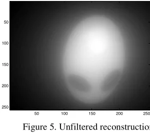
Figure 5. Unfiltered reconstruction. Figure 6. Reconstruction filter.
We can see that the image obtained is very fuzzy. To enhance its definition, the image is filtered by the filter back projection algorithm. We use filter back projection algorithm for the reconstruction of the results, you can clearly see that eliminates the surrounding interstellar artifacts, and the image is clear, the geometric shape of unknown medium is clearly visible, more intuitive, reconstruction effect is good.
According to the above algorithm, we obtained the specific shape of the object and the absorption rate
f
2(
x
,
y
)
of each of its untreated points. In order to obtain the correct treatmentf
2'( )
x
,
y
, the absorption rate of the sample in the CT system was studied. Now the information of the sample is filtered and back projection, and the unprocessed absorption rate of the sample f1'(
x,y)
is obtained. Comparison of the absorption rate in the sample table was found:(
)
'(
)
1 0
,
0 1 0,
0.
(9)
f x y
=
kf
x y
The known samples are homogeneous media so we can obtain
f
(
x
,
y
)
=
0
.
5
.Also we know 50 100 150 200 25050
100
150
200
(
,)
1' 1 x y =
[image:5.612.110.503.159.308.2]f , so according to
f
1(
x
0,
y
0)
=
kf
1'(
x
0,
y
0)
,we can obtaink
=
2
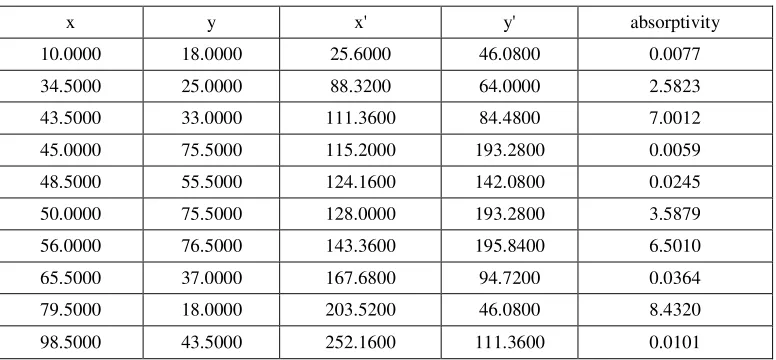
.For unknown samples we can get the treatment after absorption rate, at the same time use the conversion process will be 362 * 362 points, the coordinates of the figure into 362 * 362 calibration coordinate first, and then will be 362 * 362 figure after the calibration of adjacent two absorption value of the absorption rate of combined average write a table, as a point of absorption rate, 256 * 256 absorption coordinates is obtained.Table 1. 10 point conversion coordinates and absorption rate of the objects being tested.
x y x' y' absorptivity
10.0000 18.0000 25.6000 46.0800 0.0077 34.5000 25.0000 88.3200 64.0000 2.5823 43.5000 33.0000 111.3600 84.4800 7.0012 45.0000 75.5000 115.2000 193.2800 0.0059 48.5000 55.5000 124.1600 142.0800 0.0245 50.0000 75.5000 128.0000 193.2800 3.5879 56.0000 76.5000 143.3600 195.8400 6.5010 65.5000 37.0000 167.6800 94.7200 0.0364 79.5000 18.0000 203.5200 46.0800 8.4320 98.5000 43.5000 252.1600 111.3600 0.0101
Restore the Object under Test. Due to the same as the problem before, so according to the algorithm model is established to calculate before, first of all need to get the image calibration, simultaneously coordinates transform, get the scan images after calibration. The image is filtered again. Since the previous problem is consistent with the previous problem, the only solution given is not to be repeated.
[image:5.612.143.469.383.480.2]
Figure 7. Through the algorithm, the position shape diagram of the article is obtained, where a is uncalibrated, and b is calibrated to adjust the graph.
Treatment Absorptivity. According to the treatment of absorption rate, the absorption rate is processed the same, and 362*362 forms are processed for 256*256.At the same time, the conversion coordinates and absorption rate of ten points are obtained.
Table 2. The second is the conversion coordinate and absorption rate of ten points of the object.
x y x' y' absorptivity
10.0000 18.0000 25.6000 46.0800 0.0077
34.5000 25.0000 88.3200 64.0000 2.5823
43.5000 33.0000 111.3600 84.4800 7.0012
45.0000 75.5000 115.2000 193.2800 0.0059
48.5000 55.5000 124.1600 142.0800 0.0245
50.0000 75.5000 128.0000 193.2800 3.5879
56.0000 76.5000 143.3600 195.8400 6.5010
65.5000 37.0000 167.6800 94.7200 0.0364
79.5000 18.0000 203.5200 46.0800 8.4320
98.5000 43.5000 252.1600 111.3600 0.0101
50 100 150 200 250
50
100
150
200
250
50 100 150 200 250
50
100
150
200
[image:5.612.113.501.571.751.2]Conclusion
This article mainly focuses on the improvement of the distortion in the detection of the CT system. The first image of the CT system we get is the projection, then the projection is processed by a one-dimensional filter, and then the projection is reconstructed and the original shape of the object is obtained. The resulting image is more restored and clearer. When solving the absorption and geometry of geometric objects, it is more scientific and accurate for solving practical problems.it also Improve the working speed of the CT detection system. A number of extensions of our method may be possible, the choice of one-dimensional filter can be better. We hope that the method and ideas presented here will prove useful in the analysis of many CT detection systems, we hope more applications in the future.
Reference
[1] Shoukui Si. Mathematical modeling algorithm and application [M]. Beijing: national defense industry press, 2011:39-63.
[2] Huiyun Fan. Research on the algorithm of back projection reconstruction of CT images [J]. Biomedical engineering, 2007:1-29.
[3] Information on http://mcm.blyun.com/