2016 6th International Conference on Information Technology for Manufacturing Systems (ITMS 2016) ISBN: 978-1-60595-353-3
1 GENERAL INSTRUCTIONS
Urban traffic, because of its complicated traffic lines, large traffic density and incomplete traffic road network planning, has put forward many new requirements and difficulties for Urban Traffic
Control System (UTCS)[1]. The development trend
of the Internet has extended to various fields, especially when combines with industry. More and more devices need to achieve interoperability
through the Internet or LAN[2],and users could
achieve remote control and the information transmission, so it should be an intelligent network on this basis. The combination of industrial Internet and traffic can be very good for the traffic control system. The design of network control system based on IP could make the complex urban traffic control system an ordered intelligent network, so as to achieve rapid, efficient and accurate intelligent
control[3].
Currently, the controller is the core of UTCS, it outputs switching value through the corresponding peripheral device driver boards and control the traffic lights. In this mode, the number of the traffic lights, detectors, pipelines and the types of pipelines which will be installed at the intersection depend on the types and sizes of the intersections and the number of phases. It is a large and complex work when the project begins. So traditional traffic control system exist the following deficiencies:
(1) It has discrete structure of Printed Circuit function Boards (PCB). Its functional modules are connected stage by stage resulting in complex
structures of controller[4].
(2) The separation of network and equipment reduces the stability of the communication. The system has to access the Internet indirectly resulting in complex structures of network.
(3) Star topology architecture of wiring installation calls for independent power supply lines when peripheral equipment access to the traffic controller resulting in heavy and complex workload.
(4) There are several kinds of peripheral equipment working in parallel, which lead to different cables, working voltage, control protocol and communication protocol and result in high
failure rate and high maintenance complexity[5].
The intelligent traffic signal control system based on IP, using the "Internet of things" thinking, combined the network and traffic equipment, made traffic equipment the intelligent IP nodes in traffic control network. At the same time, each traffic facility was installed with an independent controller, so they can achieve self-control and self-monitoring. What is more, they can run according to the instructions received, can also upload their own data to the server, including sending alerts and reminders. Those IIPUs were connected with the server through the Power Line Communication (PLC) technology, which means all the traffic equipment were connected together through a group of power lines.
Network Control System of Traffic Signal Based on IP
Yongzhong Zhang, Yulin Tian, Yangyang Zhang
Beijing Key Lab of Urban Intelligent Traffic Control Technology, North China University of Technology, Beijing, China
That is easy to accomplish in engineering construction. The system adopted the structure of the Client and Server (C/S). After the establishment of the center server, all the IIPUs send connection requests to the central server, and waiting for connection. The server matched the code with the field equipment, then the system began to run traffic timing scheme. Traffic signal operation scheme of the junctions can also be monitored by the clients. The Figure 1 shows the comparison chart of the system and the traditional traffic signal control system in engineering.
a b
Figure 1. Traditional traffic signal control system (a) and network control system (b) in engineering.
2 HARDWARE DESIGN
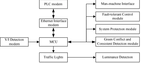
The intelligent control system consists of the intelligent IP node equipment, namely IIPU. Network communication was the foundation of the system, which means the traffic controllers of cabinet style are replaced by all kinds of intelligent IP node equipment (as shown in Figure 1, ‘LC’ has been replaced). The signal lamps are an indispensable infrastructure of the road traffic equipment, so the signal lamp node module is an important part. Each IIPU was equipped with a microcontroller as the center of data processing and control, an Ethernet communication interface module served as a connector, connecting IIPU and regional server, and a Power Line Communication modem (PLC modem) as the interface for data demodulation. The basic structure of the system was composed of those hardware units. A complete traffic control system requires more. Green signals do not appear at the same time in traffic hub part (green light of the east-west direction and north-south direction can’t occur at the same time in the intersection). Although the conflict could be avoided in the process of software design, there must be Green lights Conflict Detection (GCD) and Outputs Consistency Detection (OCD) in the hardware design when considering the traffic safety and reliability of hardware design. OCD could detect the consistency of software logic and hardware output voltage, thus could further ensure the reliability of the hardware design. Because the signal lights units
and other IPPUs work outdoors all day long, it must be able to withstand the changes of temperature, humidity, lightning and other harsh environment. So there is Fault-Tolerant Control module (FTC module) to ensure that the equipment can make normal operation according to a predetermined working mode even when the controller is damaged. Figure 2 shows the system block diagram of traffic lights module.
Figure 2. The system block diagram of IIPU.
2.1 CPU module
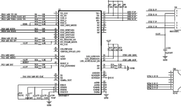
STM32F107 is a micro controller of interconnection that STMicroelectronics launched. It integrates a variety of industry standard interfaces, and has the compatibility with different types of products in pin and software. Peripherals include 10 Timers, 2 CANs, two 12-bit analog-to-digital converters, two 12-bit buffered DAC channels which can be used to convert two digital signals into two analog voltage signal outputs, two I²C bus interfaces which can operate in multi-master and slave modes, 5 USARTs, 3 SPIs (18 Mbit/s), USB 2.0 full-speed device/host/OTG controller with on-chip PHY that supports HNP/SRP/ID with 1.25 Kbytes of dedicated SRAM, 10/100 Ethernet MAC with dedicated DMA and SRAM (4 Kbytes). Furthermore, the 10/100MAC module can complete the application of Ethernet when where is a compatible Ethernet interface IC like DP83848VV.
2.2 Ethernet interface module
[image:2.612.322.548.149.250.2] [image:2.612.59.280.184.311.2]Figure 3. Ethernet interface module.
2.3 Power line communication module
Power Line Communication is a technique to realize data transmission and information exchange by using existing power lines as transmission medium. The technique modulates user’s data through Gaussian Filtered Minimum Shift Keying (GMSK) and Orthogonal Frequency Division Multiplexer (OFDM) and loads high frequency signals carrying information into the current which transfer through the power lines. Taking out the modulated signal at the receiving side after a filter, the original communication signals can be obtained after demodulation. When the demodulated signal is transferred to the computer or telephone, the information transfer is completed. Power Line Communication has a high economic efficiency and reliability, because the mechanical strength of the power line is high. It does not require new line infrastructure investment and routine maintenance costs. The technology also has the advantages of plug and play, no wiring and easy to move. PLC modem is the key equipment to realize PLC technology. The design used the electric power modem equipment TL-H29RA&H29EA, the device supports IEEE 802.3. Table 1,Figure 4-5 show the results of test on packet loss, TCP throughput, and delay jitter, the results show that the average rate of the wireless transmission of the power modem is 110.90Mbps, the packet loss rate is 0%, the average jitter is 0ms. Therefore, it can be used as a reliable network communication line of the system.
Table 1. The results of packet loss.
The i test
TCP Max Rate (Mbps)
TCP
Min Average TCP Rate (Mbps)
IPLR Shake
Rate
(Mbps) (%) (ms)
[image:3.612.289.552.49.635.2]1 39.75 30.08 35.49 0 0.44 2 40.22 22.73 29.21 0 0.61 3 37.89 30.91 33.82 0 0.39 4 38.47 31.25 34.1 0 0.47 5 38.71 30.87 33.91 0 0.41 Average 39.01 29.17 33.31 0 0.46
[image:3.612.347.524.521.632.2]Figure 4. TCP Throughput of PLC module.
Figure 5. Delay Jitter of PLC module.
2.4 Detection module
detection modules are important parts of testing the working status of IIPUs. As the Figure 6 shows, the current detection module is composed of a current transformer (TA1013) and a bridge rectifier (MB6S) in the design. By appropriately adjusting the value of the sampling resistance, it can be used to detect the change of current in different IIPUs. That means the current detection module is a standardized detection unit for traffic equipment, including the devices that are used in current traffic control system.
Figure 6. The schematic of current detection module.
2.5 Driving module
Traffic equipment is usually powered by alternate currents, so the system is designed with the standard driving circuit which could drive high voltage load through weak current controller. In the design, BTA16-800BST is used as the driving IC of high voltage load which is a high-power drive IC. The driving module was designed for high performance full-wave ac control applications where high noise
immunity and high commutating d ⁄ d are
[image:4.612.322.559.208.401.2]required. Blocking voltage to 800 V, on-state current rating of 16 A RMS at 80°C, the high voltage load driving module can drive almost all the traffic facilities load. To increase the isolation and improve the safety factor of the circuit, the module was designed with high voltage output indicator (DetR1, Figure 7) and two isolator (BTA16-800BST and MOC3063), Figure 7 shows the specific schematic diagram.
Figure.7. The schematic of driver module.
3 SOFTWAREDESIGN
The main body of the software design was the work style of each IIPU and cooperation between the
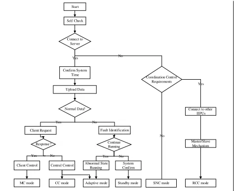
various units. Each IIPU has its own device code, MAC address, port number and configurable IP address. After each device was powered on, it got its own variety of data information, analysis of the state, and then sent connection requests to the central server. Before successfully connected, IIPUs ran in accordance with the established mechanism. After the center server responded to the connection request and allowed the device to be accessed, IIPUs confirm the system time with server to make sure the operations between different IIPUs can be consistent, and then sent their necessary data and wait to be confirmed. Figure 8 shows the design process of system software.
Start
Self Check
Connect to Server
Confirm System Time
Upload Data
Normal Data?
Client Request
Coordination Control Requirements No
Fault Identification
Continue Running
Connect to other IIPUs
SNC mode No
Master/Slave Mechanism
RCC mode Yes
Client Control Central Control
MC mode CC mode
Response?
No Yes
Abnormal State Running
Yes System Confirm No Yes
Adaptive mode Standby mode No
Yes
Figure 8. The design process of system software.
[image:4.612.66.286.517.658.2]of malfunctioning, this is the Single Node Control mode (SNC mode). SNC mode is not the regular mode, so it will not run for a long time.
To realize the intelligent management and control of the whole road network, 6 modes of IIPUs were designed. CC mode is the common solution of traffic coordination control system. It is a focus on the overall situation of the control scheme. MC mode is a way to deal with the special needs of the traffic, in which user could manually control the change of phase and time length. Adaptive mode improves the operational stability of IIPUs when taking a single intersection as the smallest unit of the system. Compared with SNC mode, RCC mode could control multiple intersections harmoniously in the region which is suitable for coordinated control. Additionally, RCC mode can reduce the load of central server.
[image:5.612.68.288.375.527.2]The design (Figure 9 shows the IIPU of traffic light) achieves the effect of streamlined structure, precise control, coordinated operation and intelligent control after testing and analyzing the system in a number of actual junctions. The system was tested in the 6 modes, artificial settings of electrical fault and long term stability testing. The results show that the system can realize the intelligent transportation and network control based on IIPUs.
Figure 9. The IIPU of traffic light.
4 CONCLUSIONS
(1) The design improves the cost, installation, compatibility and other problems of current signal control system with the thought and concept of "the Internet of things".
(2) The system can reduce the engineering cost and the difficulty of implementation when all the standardized IP node devices are connected in series to the network by using a set of cables, combined with a power line modem. It can realize the intelligent control of the whole intersection.
(3) The system changed the control thinking of traditional traffic signal control systems. It has the function of IP access, self-examination and
independent control when each IIPU is configured an independent controller.
(4) IIPUs could not only realize the control of the intersection, but also achieve the coordination control of other intersection in the corresponding mode. Local control signals could be crossed over the local device to the next intersection, and the traffic phases are running on the network.
(5) The promotion and implementation of the control system can achieve the network monitoring and management in the area covered by the system, and it is also the basis of the Wireless Car. Traffic control will break the limit that traditional traffic’s single node control and local control, and achieve traffic intelligent control focus on the overall situation.
5 ACKNOWLEDGEMENTS
This design is partially supported by Ability Construction of Innovation of Scientific
Service-Collaborative Innovation Center-Collaborative
Innovation Center of World Cities Smooth Traffic of Capital-Participants PXM2016_014212_000030 and Capacity Construction of Scientific Innovation
Service-Transformation of Scientific and
Technological Achievements-Upgrade
Project-Support System Development of Decision of Traffic Dredging and Congestion for Beijing Road Based on Big Data of Traffic PXM2016_014212_000036. The authors gratefully thank anonymous referees for their useful comments and editors for their work.
REFERENCES
[1] HeJinfang & Long Ling. 2015. The Hardware Design of Intelligent Management System for Traffic. Proceedings of 2015 2nd International Conference on Civil, Materials and Environmental Sciences (CMES 2015)
[2] Zhao Jun. 2015. Research on Prediction of Traffic Congestion State. Proceedings of the 2015 2nd International Conference on Engineering Technology and Application (Volume 1)
[3] Ge Hongxia & Meng Xiangpei & Ma Jian & Lo Siuming. 2012. An improved car-following model considering influence of other factors on traffic jam. Physics Letters A . 2012 (1-2)
[4] Cheng Rongjun & Han Xianglin & Lo Siuming & Ge Hongxia. 2014. A control method applied to mixed traffic flow for the coupled-map car-following model. Chinese Physics B .