2020 4th International Conference on Modelling, Simulation and Applied Mathematics (MSAM 2020) ISBN: 978-1-60595-674-9
Voltage and Loss Control for Long Range 10kV Power Transmission
Based on Virtual-gap Controlled Reactor
Wu-bin LIN
1, Yuan-huan LIAO
1, Xiao-hua LIAO
1and Xu-xuan CHEN
2,3,*1
Sinopec Marketing South China Branch, Guangzhou 510620, China
2
Wuhan University, Wuhan 430000, China
3
Wuhan University of Science and Technology, Wuhan 430000, China
*Corresponding author
Keywords: Controlled reactor, Reactive power control, Saturation, Simulation.
Abstract. The reactive power compensation problem prevalent in modern power systems makes the
power distribution performance not fully utilized and the load power consumption of the equipment increases. According to the operation of the Yulin substation line and the load, the theoretical calculation of the reactive power compensation scheme is developed. The installation capacity, installation position, control scheme of the intelligent magnetic control reactive power compensation system are researched. Through the coordinated control at the beginning and the end of the line, the real-time regulation of the reactive power in the substation and the transmission line can achieve the effect of stabilizing the whole area voltage, improving the power supply radius and power quality. The system finally implemented the stability of the substation voltage and reduced the line loss, made the voltage of the power system stable within the utility required range.
Introduction
At present, some substation of the oil transfer station is far away from the superior substation, and the line length is long. When the line load is large, the line voltage drop is too large, which will lead to the failure of the motor and other important loads and seriously affect the normal production. In order to maximize the performance of distribution equipment and reduce power consumption, the modern power system uses various methods to compensate for reactive power.
Voltage is the main quality index of electric energy, which has a direct impact on the stability of power grid, functions and residents' life. According to the state grid power system voltage quality and reactive power management regulations, the allowable voltage deviation of the 10 (6) kV bus of the substation directly under the normal operation mode is 0-7% of the rated voltage of the system. Voltage quality objectives:
1) annual grid voltage qualification rate reaches 99.0%;
2) the qualified rate of annual power supply voltage is above 98.0%.
Aiming at the high requirement of voltage qualification rate, it is of great significance to strengthen the adjusting ability of reactive power and adjust the bus voltage reasonably and scientifically to improve the voltage qualification rate, stable region voltage, and voltage quality.
This paper studies the virtual-gap controlled reactor (VCR) for intelligent and dynamically control of the reactive power compensation capacity, line length, transmission efficiency to reduce the loss of the power transmission. The paper proposed a load adaptive coordination control strategy. Through the optimal allocation of reactive power, the method provides optimal operation schemes economically which can improve the power quality, increase power supply radius and reduce the loss of line.
The Operation Principle of the VCR
coupled together to minimize the volume of the VCR. Since the control winding shares a common part of the main winding, the thyristors on the control winding will not withstand the rated operation voltage of the VCR in the primary winding. The coupled ratio is only about 5% so that the power electronic control circuit has a high stability against power turbulence or transient overvoltage.
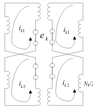
Figure 1. Structure of the single-phase VCR.
Eg
Nk
T1 T2
δ 1 k i 2 k
i ik2 Nk/2
1
k
i
[image:2.595.338.492.147.329.2]k
e
Figure 2. Working principle of the VCR.
As shown in Fig.1, there are 4 taps in the control windings, each thyristor connects two of them on the same side. Take T1 as an example, the voltage upon the thyristor T1 is positive when the voltage of the source Eg is positive. T1 can be conducted and forms a circuit in the upper side in which ik1 flows. Since thyrister T2 is not conducted, the voltage upon the taps forms two sources on the left control widing. When the voltage of the source Eg is negative, the analysis is the same and forms a symmetry circuit compared to that when T1 is conducted. The equivalent circuits are shown in Fig.2 The operation principle is that the thyristors are conducted periodically. The digital control system can regulate the magnitude of the currents ik1, ik2 when the firing angle of the thyristors are controlled. In a power-frequency cycle, T1 and T2 are triggered into conduction in turns, generating control current ik1 and ik2, which puts the working iron cores in a saturation state and increases the output
current.
The voltage ek in the control widing is calculated as,
0
1
2
2 ( ), sin( )
1
1 ( )
0
k g g m
e e K t e E t
T conducted K t T conducted (1)
From equation (1), rewritten ek as
2 sin 2
1 1 cos
1 (1 )
m m E E e d k
(2) And the current flows in the winding can be expressed as,(1 cos )
4 (1 )
(2 ) 1 k m k E E i R R
1 1 1
2 2 2
1 1
2 2
( ) ( )
g k k
g k k
i N i N lH
i N i N lH
H f B
H f B
(4)
From equations (2) to (4), the firing angle α has a great impact on the control current and further regulates the output current. The output current can be regulated with no step value by continuously changing the control angle α.
In equation 4, the functions also describe the magnetic behavior in the iron cores. To further explain the functions, Fig.3 is drawn.
B
H ωt
Bs
-Bs
B
H
ω
t
0
tg
B1
B2
2Bs
0
0
0
β
H1 H2
H2
ω
t
0
i
[image:3.595.205.391.230.441.2]i
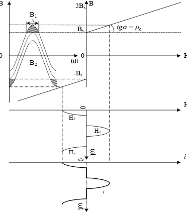
Figure 3. Working principle of the saturable core.
The figure shows the iron cores are saturated when the control current is positive. The saturation degree β is introduced to define the saturation of the iron cores,
2arccos s d s
B B
B
(5)
where Bs is the magnetic density when the iron core begins to saturate; Bd is dc biased magnetic density produced by ik.
Since Bd can not be greater than Bs, the maximum value of β is 2π.
Implementation and Simulation
Due to the heavy impact load, the voltage fluctuation of the Yulin substation is high. However, there is only one main 10kV power transmission line for the Yulin substation. The length is 7.95km and the type is LGJ-185. However, there will be a maximum 2.4 MW impact load when large motors are operating. As can be seen in Fig. 4, the voltage is only 9.386 when the load becomes 2MW.
[image:3.595.130.482.692.754.2]If the load continues to increase, the voltage will continue to decrease. The voltage does not meet the requirements of the operation of the pump motor and the line loss increases. In order to increase the voltage at the end of the transmission line, a dynamic reactive power regulator must be installed.
The electrical parameters of the installed equipment in this station are shown in Table. 1.
Table 1. Load parameters in the substation.
Load parameters Total Load P(kW) Cosφ Number P(kW) Q(kVar)
Type I Fuel pumps 1650 0.89 2 3300 1690.64
Type II Fuel pumps 830 0.89 1 830 425.22
Others 180 0.9 1 180 87.18
From Table.1, in order to meet the power factor not less than 0.95, the reactive power compensation capacity of the VCR required is 800kvar.
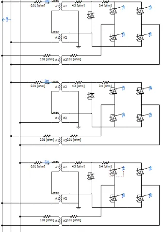
[image:4.595.221.390.280.520.2]The 3-phase model of the VCR for reactive power compensation is shown in Fig. 5.
Figure 5. Delta-connected VCR for reactive power compensation.
[image:4.595.194.415.596.702.2]The rated outputs current of the 800kvar VCR is shown in Fig.6. The VCR can continuously regulate the output current until rated value. The harmonics in the currents are very low, and the parameters all meet the national standards.
Figure 6. 800kvar VCR rated current output waveform.
Figure 7. The simulation when all fuel bumps are in operation.
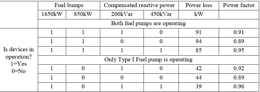
Power loss in the transmission line is also decreased. There are several operation states of all the fuel pumps. However, the reactive power compensation is continuous. The Power loss comparison are listed in Table 2 when compensated reactive power is different. There are 3 points to compare power loss. From the results, it can be seen that, if the power factor can be kept above 0.95, the power loss can be significantly decreased.
Table 2. Power loss comparison when compensated reactive power is different.
Fuel bumps Compensated reactive power Power loss Power factor
1650kW 850kW 200kVar 450kVar kW
Both fuel pumps are operating
Is devices in operation?
1=Yes 0=No
1 1 1 0 91 0.91
1 1 0 0 94 0.89
1 1 1 1 85 0.95
Only Type I Fuel pump is operating
1 0 1 0 42 0.92
1 0 0 0 44 0.89
1 0 1 1 39 0.96
Summary
In this paper, a new method based on VCR is proposed to reduce the loss of long-distance 10kV transmission lines with heavy loads. Through comprehensive control, the terminal voltage is controlled within the utility required range, the power factor is not less than 0.95, and the line loss ratio is reduced by about 5% to 10%, which not only solves the problems of voltage regulation and load balance, but also meets the requirements of line loss, and has a good application value.
Acknowledgment
This research was financially supported by Sinopec Marketing South China Branch (contract NO. 30251731-18-ZC0607-0009).
References
[1] R. R. Karymov, M.Ebadian, “Comparison of magnetically controlled reactor (MCR) and thyristor controlled reactor (TCR) from harmonics point of view,” Electrical Power and Energy Systems. Vol. 29, pp. 191-198, Jun. 2006.
[image:5.595.88.510.320.470.2][3] Bryantsev, A., Bryantsev, M., Bazylev, B., et al. Power compensators based on magnetically controlled shunt reactors in electric networks with a voltage between 110 kV and 500 kV[C]. Transmission and distribution conference and exposition, Sao Paulo, Brazil, 2010, pp: 239-244. [4] X. X. Chen, B. C. Chen, C. H. Tian, J. X. Yuan and Y. Z. Liu, “Modeling and Harmonic Optimization of a Two-Stage Saturable Magnetically Controlled Reactor for an Arc Suppression Coil”, IEEE. Trans. Industrial Electronics. vol. 59, pp. 2824-2831, Jul. 2011.