2016 International Conference on Electronic Information Technology and Intellectualization (ICEITI 2016) ISBN: 978-1-60595-364-9
The Design of a Low Dielectric Constant Plate
Microstrip Antenna
Shangsheng Li, Weijie Li, Xiang Ling and Jing Yu
ABSTRACT
This paper introduces a design of a low dielectric constant plate rectangular micros trip antenna. In order to meet the requirements of the radar simulator on antennas, a rectangular micros trip antenna whose dielectric plate is made of PTFE is designed, the relative permittivity of PTFE is 2.2. Emulating the antenna with software named ADS2011, simulation results show that, compared to the traditional microwave material named epoxy resin(FR4),whose relative dielectric constant is 4.4, the rectangular micros trip antenna has a higher gain, better suited for radar simulator.
INTRODUCTION
Active radar is a core component on a certain type of weapon system, in order to reduce the cost of training, replacing mounting radar with radar simulator on weapon system technology ready for training is needed. According to the functional requirements and size constraints of simulator, the main technical indicators of a single antenna on simulator antenna system are determined as follows:
①Working frequency: 15.9GHz;
②Antenna gain: not less than 5dBi;
③Antenna aperture size: not more than 25mm.
Considering the requirements of lightweight and portable as well as the form of polarization, simulator uses microstrip antenna. Microstrip antenna has the
_________________________
advantages of small size, light weight, conformal with the carrier, the electrical properties of diversification, ease of integration, but its gain is low. Therefore, in the antenna design, increasing the gain to meet the requirements of the simulator indicators is the key considerations.
There are a number of ways to improve the gain of microstrip antenna. D.R. Jackson and N. Galexopouls proposed using the upper substrate[1][2], the literature [3][4]proposed using multi-layer patch structure to achieve high-gain of the antenna, and some proposed using active load to achieve. Based on the idea of "magnetic current loop does not excite a certain radius of a surface wave, the radius of the same annular microstrip antenna can’t provoke wave radiation, so as to obtain a smooth narrow radiation pattern thereby improving antenna gain." the literature[5]proposed two high-gain circular short ring antennas. The literature[6]increased the antenna gain through a ring-shaped thin-walled metal shorted to ground plate at the center of a rectangular ring microstrip antenna and a circular ring microstrip antenna.
In this paper, based on the impact of the dielectric plate permittivity to antenna gain, having rectangular microstrip antenna for example, which is the most commonly used, with the help of simulation software ADS2011, two kinds of rectangular microstrip antenna which have the same thickness, the same frequency (15.9GHz) but a different materials are designed. In the simulation, the change of antenna dielectric plate material is simulated by changing the relative permittivity of the dielectric plate, the simulation results show that dielectric plate made of PTFE whose relative dielectric constant is lower does help increasing gain to meet simulator indicators.
ANTENNA STRUCTURE
The design of the antenna structure is shown in Fig. 1. It contains a dielectric plate, ground plate, patch antennas.
The value of patch antenna length L is half of the medium wavelength theoretically, and the general value of width W should be less than L. When W is larger than L, the higher order modes will produce and lead to a distortion field [7].
Thus, for antenna working in 15.9GHz, its operating wavelength is 1.89cm. If epoxy resin (FR4) is used in dielectric plate, whose dielectric constant is 4.4, its medium wavelength is as follow:
cm g 0.9
Thus, width W takes 0.44cm.
If poly tetra fluoro ethylene (PTFE) is used in dielectric plate, whose dielectric constant is 2.2, its medium wavelength is as follow:
cm r
g 1.27
2 . 2 89 . 1 (3)
Patch length is as follow:
cm
Lg /20.64
(4)
Thus, width W takes 0.62cm.
2 g
W
[image:3.612.170.420.309.477.2]Ohm Z050
Figure 1. The structure diagram of micros trip patch antenna.
DESIGN AND SIMULATION ANALYSIS
Figure 2. S (1,1) simulation results.
The Design and Simulation of FR4 Dielectric Plate Antenna
With FR4 dielectric substrate(Er 4.4,tan 0.02,h1.6mil), rectangular
micros trip patch antenna working in 15.9GHz is designed in ADS Layout, its feed method uses micros trip feed.
Simulation frequency range is configured to 15GHz ~ 17GHz, the way is swept. Emulator is Momentum Microwave.
The simulation results are shown in Fig.2.
As is shown in Fig.2, center frequency of S-parameters is 15.9GHz, input return loss value S (1,1) at the working frequency 15.9GHz reaches -28.388dB, meets the demand of VSWR. Thus, the micros trip antenna doesn’t need to match and optimize in the design.
The Design and Simulation of PTFE Dielectric Plate Antenna
With PTFE dielectric substrate(Er 2.2,tan 0.003,h1.6mil),rectangular
[image:5.612.191.405.225.359.2]micros trip patch antenna working in 15.9GHz is designed. The simulation results are shown in Fig.4. As is shown in Fig.4, center frequency of S-parameters is 15.9GHz, input return loss value S (1,1) at the working frequency 15.9GHz reaches -3.77dB, does not meet the requirements of VSWR. Thus, the micros trip antenna needs to be matched and optimized.
Figure 4. S (1,1) simulation results.
Matching Design
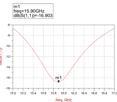
Use ADS Smith chart tool to match the patch. There are a variety of matching networks to transform patch impedance to 50Ωfeeder. Here we select microstrip line for matching, namely trans form patch impedance to 50Ωfeeder through a period of microstrip. As is shown in Fig. 4, the impedance of microstrip patch in 15.9GHz is 102.3-j*109.5Ω. Match antenna at 15.9GHz through ADS Smith chart tool. The results show that a microstrip line whose characteristic impedance is 130
Antenna pattern shows that the gain of micros trip antenna reaches 5.22dBi, meets the demand of simulator to the antenna.
Analysis of Simulation Results
Simulation results show that the low dielectric constant dielectric plate does have a higher gain than the high one, but inevitably increases the size of the antenna. It is easy to calculate, PTFE dielectric plate antenna overall size is 11.4mm×
6.2mm, in line with the simulator antenna size requirements.
Therefore, considering the simulator antenna index requirements, PTFE dielectric plate antennas are standard as a receiver antenna on radar simulator.
CONCLUSION
[image:7.612.194.402.429.562.2]This paper describes the design method for micros trip antenna on radar simulator which has a low dielectric constant plate. Emulating microstrip antenna models via software ADS2011, in order to achieve the indicator of the radar simulator, these models are analyzed and compared from the working frequency, gain requirements and size limitations. Ultimately PTFE dielectric plate antenna which has low dielectric constant material meets all requirements, making useful exploration for the promotion of microstrip antenna in the simulator field.
Figure 6. S (1,1) simulation map after matching.
REFERENCES
1. D.R. Jackson and N. Galexopouls, Sept. 1985, “Gain enhancement methods for printed circuit antennas”, IEEE Trans AP, vol. 33, no 9, pp. 976-987.
2. H.Y. Yang and N. Galexopouls, July 1987, “Gain enhancement methods for printed circuit antennas through multiple superstrates”, IEEE Trans AP, vol. 35, no. 7, pp. 860-863.
3. Wonkyu Choi, Cheolsig Pyo, and Jacick Choi, October 2003, “A high-gain microstrip patch array antenna using a superstrate layer”, ETRI Journal, vol. 25, no. 5, pp. 407-411.
4. Shigeru Egshira and Eisuke Nishiyama, November 1996, “Stacked microstrip antenna with wide bandwidth and high gain”, IEEE Trans AP, vol. 44, no. 11, pp.1533-1534.
5. Gao Jun, Yuan Zi-dong, Cao Xiang-yu, 2014, Novel high gain and low RCS microstrip antenna [J], Journal of Xi Dian University, 8(4): 158-162. (In Chinese)
6. Wang Hao, Shi Xiao-wei, Liu Shu-fang, 2012, Design of a Broadband and High Gain Microstrip Antenna at Ku Band [J], Journal of Microwaves, 10(5): 44-48. (In Chinese)