GAI8-2081-1
File No_ S360/S370/S3/4300/81 00-09
Systems
-- -- -- --
-
- - - -
--
-
---- ----
-
-Systems
GAI8-208I-1
File No. 8360/8370/83/4300/8100-09
IBM 3270
Information Display System
3276 Control Unit
Display Station
Description and
Programmer's Guide
Warning: This equipmen~ generates, uses, and can radiate radio frequency energy and, if not installed and used in accordance with the instructions manual, may cause interference to radio communications. It has been tested and found to comply with the limits for a Qass A computing device pursuant to Subpart J of Part 1 S of FCC Rules, which are designed to provide reasonable protection against such interference when operated in a commercial environment. Oper-ation of this equipment in a residential area is likely to cause interference, in which case, the user, at his own expense, will be required to take whatever measures may be required to correct the interference.
Second Edition (May 1983)
This major revision obsoletes GAI8-2081'(). Changes or additions to the text and illustrations are indicated by a vertical line to the left of the change.
Changes are made periodically to the information hereint before using this publication
in connection with the operation of IBM systems, consult the latestlBM System/370 BibliogrQphy, GC20'()OOI, for the editions that are applicable and current.
References in this publication to IBM products, programs, or services do not imply that IBM intends to make these available in all countries in which IBM operates. Any reference to an IBM program product in this publication is not intended to state or imply that only IBM's program product may be used. Any functionally equivalent program may be used instead.
Publications are not stocked at the address given below. Requests for mM publications should be made to your IBM representative or to the mM branch office serving your' locality.
A form for readers' comments is provided at the back of this ~ublication. If the form has been removed, comments may be addressed to mM Corporation. Department 812Jt 1133 Westchester Avenue, White Plains, New York. 10604. U.S.A. IBM may use
or distribute whatever information you supply in any way it believes appropriate without incurring any obligation to you.
Preface
This publication provides management, progranuners, and system analysts with detailed reference material relating to the IBM 3270 Information Display System 3276
Control Unit Display Station.
Organization of This Publication
This manual is organized into the following 9hapters:
Chapter 1, 3276 Control Unit and Data Streams.
Chapter 2, Terminals. This chapter, divided into two main sections, provides general information about displays and printers. The "Display" section presents detailed infonnation about display fields, keyboards, selector·light· pen operations, the security keylock, and the magnetic card reading device. The ''Printer'' section discusses printer capabilities and control, including formatting, orders, buffered operation, SNA character string, and copy func·
tions. (See also IBM 3230 Printer Product Description,
GA24·3759, IBM 3262 Printer Component Description, GA24-3741,IBM 3268 Printer Component Description,
I
GA27·3268, IBM 3178 Display Station Description,GAI8·2127, IBM3270 Information Display System: Color and Programmed Symbols, GA33-3056, IBM 3287 Printer Component Description, GA27-3135, and
IBM 3289 Line Printer Component Description,
GA27-3176.)
Chapter 3, Remote Operations-BSC, treats the 3276 Models 1,2,3, and 4.
Chapter 4, 3276 SNA/SDLC Communication, describes SNA and SDLC protocols for the 3276. It also presents SNA reference data applicable to the machine.
Chapter 5, Screen Design, introduces important 3270 concepts. Shows an example of what a 3270 di~play message might look like, what coding elements are re-quired to write this message in your program, and how tenninal operator input might be handled.
Chapter 6, Screen Management, suggests macro defmitions and programming routines that might be written to encode and decode messages to and from the display.
Reference material is arranged in the following appen-dixes:
Appendix A. Indicators and Controls
Appendix B. Buffer Address I/O Interface Codes
Appendix C. Status Indicator Codes
Appendix D. APL/Text Feature
Appendix E. Katakana Feature
Appendix F. Encrypt/Decrypt Feature
I
Appendix G. Record Formatted Maintenance Statistics (RECBMS) FormatsRelated Publications
Information concerning the Multiuse Communications Loop, used to attach 3270 devices to 8100 Information Systems, is contained in:
• IBM 8100 Information System: Communications, Loop, and Display/Printer Attachment Description, GA27-2883
• IBM Multiuse Communications Loop Planning Guide,
GA23·0033
• IBM Multiuse Communications Loop Installation Guide,
GA23·0039
The two Multiuse Communications Loop publications refer· red to above and the following IBM 4300 Processor
publications provide information concerning attachment of the 3276 to the 4331 Processor via the 4331 loop adapter:
• IBM 4300 Processors Summary and Input/Outpu"t & Data Communications Configurator, GA33-1523
• IBM 4331 Processor Functional Characteristics and Processor Complex Configurator, GA33-1526
Publications describing the printers and displays attaching to the 3276, the 3270 data stream, the use of color, and programming information, are listed in the publication IBM 3270 Information Display System, Library User's Guide,
Contents
Chapter 1. 3276 Control Unit and Data Streams .••.••• I-I
Introduction .•••....••••.•.••••...••••• I-I Interface Codes . . . • . • • • . • • . . . • . . • • . .. 1-3 Device Addressing .. . : • • • • • . . • . . • . . • • . • • ',' 1-3 Data Stream. . . • . . • • • • . . . • . . . • •. 1-7 Commands . . • • . • • • • • • • . . . • • . . • • • • .• 1-8 Write Commands • . . . • • • • . . . • . • . • • . . .• 1-9 Write Command . . • • . • • • . . • . . . . • . . • . . . • 1-9 Erase/Write Command . • • • • • . . • • • . . . . • • . . . 1-12 Erase/Write Alternate Command. . . . • • • . . . • • •. 1-12 Write, Erase/Write, and Erase/Write Alternate
Commands (LU Type 3) .•••.•...••..••.••• 1-15 Read Commands • • . • • . • • . • . . . • • • . . . 1-17 Read ButTer Command . • • • . . • . . . . • • . . • . • . 1-17 Read Modified Command • • . . • . . . . • . • • . . • • . 1-18 Read Modified All Command . . . • . • • . . . • • 1-22 Inbound Transmissions • . . • • • • . . . . • . • . • . . . • 1-22 Read States • • . • . . • • . • . • • . . . • • . • • . . • 1-22 Host Acknowledgments • • • • . . . • • • •• 1-24 Processing of Read Commands . . . • . . . .• 1-25 Control Commands. • • . . . • . . . •• 1-27 Copy Command . . . • • . . . • . . • • 1-27 Erase All Unprotected Command . . . • . . . • . • • 1-30 Orders . . . • . . . • . . . • • . . • .• 1-30 Start Field (SF) Order . • . . . • . . . • • . • . . 1-31 Set Buffer Address (SBA) Order . . . • . . • . . . • 1-32 Insert Cursor (lC) Order. . . • • .• 1-32 Program Tab (PT) Order . . . • . . • . . . • . . • . • 1-32 Repeat to Address (RA) Order . . . • . . . • • . .• 1-33 Erase Unprotected to Address (EUA) Order . . . • . • . 1-33
Chapter 2. Temlinals . . . • • . . . • . . . 2-1 Displays . . . . • . . . • . . • . • . . • . . . . • . . • 2-1 Display Images . . . • . . . . • . . • • . • . 2-1 Display Fields. . . . • . . . .' . . • • . . . .• 24 Attributes . . . • . . • . . . . • 2-5
Field Attributes . . . • • . . . • . . . . 2-5 Field Attribute Character . . . • . . . . •• 2-5 Base Color Mode . . • . . . • . . . . • . • . . . • . . • . • 2-6 Keyboard Operations . • • • • . • . . . • . . • . . . • . . . • 2-7 Cursor . . . • • • . . . • . . . • . . . 2-7 Keyboards. . . • . . . • . . . . • . • • . 2-7 Key Functions .. • . . . • • . . .• 2-8 Automatic Sldp . . . • • . . . • . . . . • • • • • . 2-8
Character~rlented Keys . • • . . . • . . • • • . 2-9
Field~rlented Keys . • . . • . . . • .• 2-9 Erase EOF (Erase to End of Field) Key • . . . • • . 2-10 ERASE INPUT Key . . . • • . . . • . . • . 2-10
I
INS (Insert) Mode Key (3178,3276,3278, or 3279) .. 2-10Delete Key (3178,3276,3278, or 3279) . . • . • . . . . 2-11 RESET Key . . . • . • . • • . . . • 2-11 DUP (Duplicate) Key . • . . . • • . . 2-12 FM (Field Mark) Key . . . 2-12 Program Attention Keys . . . 2-12 SYS (System) REQ Key . . . • . . • . • . . . • • • . 2-13 DEV CNCL (Device Cancel) Key. . . • . . . • . • 2-13 (SHIFT Key) - 3178, 3276, 3278, or 3279 • . . . • 2-14 (LOCK Key) - 3178,3276,3278, or 3279 . . . • . • . . 2-14 (NUM Key) - 3178, 3276, 3278, or 3279 • . . . ' 2-14
(NUM LOCK Key) - 3178,3276,3278, or 3279 •... , 2-14 (Alpba Key) - 3178,3276,3278, or 3279. • • . . . 2-14 CURSR SEL (Cursor Select) Key . . . . • • • . • . . . . 2-14
ATTN (Attention) Key • • • • • • . . • • • • • • • • • • • 2-15 CURSR (Cursor) BLINK Key. • • • . . • • • • • • • . • • 2-15 ALT CURSR (Alternate Cursor) Key • • • • . • • • • • • 2-15 TEST Key. . . • . . • • • • • • • • • . • • • . • • . • • 2-15 (Click Key) . • • . • . . . . • • • • • • • • • • • • • •• •• 2-16 (Print Key) •. . . . ~ . . • • • • . • • • • • • • • . • • •• 2-16 IDENT Key . . . • • • • • . • • . • • • • • . • • •• 2-16 Dead Keys, Canadian-French Keyboards ••••••.••• 2-17 Numeric Lock Feature Operation •.•••••..••••• 2-17
Keyboard Disabled (Do Not Enter Condition) ••••••• 2-18
Selector-Ljght-Pen Operations .••••••.••••••.•• 2-20 Selector-Light-Pen Field Format . • • • • • . • • • • • • •. 2-20 Designator Characters •.••••.•••••.•••••••• 2-21 Security Keylock • • . • • . • . . • • '. • • • • • • • • • • • .• 2-23 Magnetic Slot Reader .•.•...••••.•••••••••• 2-24 10-Cbaracter Set •.••..••.•••••••••••••.. 2-25 Magnetic-Stripe Format . . . • • . • . . . . • • • • • • . •• 2-26 Operational Differences because of Screen Format •••. 2-26 Error Conditions . • • . . . i. • • • • • • • • • • • • • • • • • 2-30 MSR Validity Test . • . . • • • • . • • • • • • • • • . • • •• 2-30 MSR Operator Indicators and Alarm • • • • • • • • • • • • • 2-31 Printers . . . • . . . • • • . • . . . • • • • • . . • '. • 2-32 Print Line Formatting •...••••••.••••••. ' •.• 2-32 Printer Orders. . . • • • • • • . . • • • . • • • . •• 2-34
New Line (NL) and End of Message (EM)
(All Printers) . . . • . . • . • . . • • . • . . . • . .• 2-34 Forms Feed (FFJ(All Printers) •••••.•.•.•..• 2-34 Carriage Return (CR)
(All Printers) •.•.. . . . • • • . • . • • . • • • . • • • • 2-34 Buffered Printer Operations ..•...••••.••.••• 2-35 Page Length Control Operations • . • . • . • . • . • • • •• 2-35 SNA Characters String
(All Printers) • . . . • • . . • . . • . . ~ . . . . 2-36 SCS Control Codes. . . • • . • • • • • • • • • . • • •• 2-36 Program Attention (p A) and
Cancel Print Switcbes .. . . . • • • • . . . • • . . . 241 Print Format Control . . . . • • . . . . • • • . . . • • . • . 241 Local Copy Function . . . • . . • . • . . . • . . • • • • 242 3276 Default Matrix . . . • • • . • • • . . • . • 242 3276 Local Copy Operation • . . . • . . • • . • • • . . . 243 Host-Initiated Local Copy Using SNA/SDLC . . • . • • . 245 Local Copy Performed without SNA Protocol • • • • • • 247 Mono/Dual Case Control . • . . . • • • • . . • . . • . • • 248 Format Control during Shared Printer Operations . • •• 248 Error Conditions • . . . • • . . • . . . • • • • . . . • 2-50
Chapter 3. Remote Operations - BSC . . • . . . ; •• 3-1 Introduction . . . • . . • . . . • 3-1 Code Structures . . • . . . • • • • . . • • . . • . • • . 3-1 Channel Program Concepts . . . . • • . • • . • • . • • • • • 3-1 Text Blocking . . . • . • . . . . • . . • • • . • . • • 3-1 Related Publications . . . • . . . • . • • . . • . . • • • 3-2 Multipoint (Nonswitched Line) Data Link Control ••••. 3-2 3276 Modes of Operation ...•.•••.••••.••••. 3-2 Control Mode. • . . . . • . • • . • • . • • • • • • • • • • • 3-3 Text Mode . . . • . • . . ~ • . • . • • • • . . .• 3-3 Transparent Monitor Mode . . • • . • . . . • • .'. . • •• 3-3 Redundancy Checking . . • • • . • . . • • . . . • . . • • 34 Data-Link Control Characters. . . • • . . . • • • . • • • . . 34
Pad .•••.•••••••••••.•••••••••••••• 3-5 SYN (Synchronous Idle) • . . . • • • • . • • . . . • • 3-5 DLE (Data Link Escape) . • . . . • • . • . . • • • • . . . 3-5
ACK 0 (Even Acknowledge) • . . . . • • . . . • . • • . • 3-6 ACK 1 (Odd Acknowledge) • • • . • • • . . . • • • . . 3-6 NAK (Negative Acknowledgment) . . . . • . . . . • . •• 3-6 ENQ (Enquiry) . . . • • . . . . • • • . . . 3-6 WACK (Wait before Transmit) . . • • • . . • • • • • . . . 3-7 RVI (Reverse Interrupt) •.••.•..•.••.•••••• 3-7 STX (Start of Text) . • . . • . . • • . . • . . . • • • • 3-7 SOH (Start of Heading) . . . • . . . . • . . . • • . •• 3-7 ETB (End of Transmission Block) . . . . • • • . . • • . • 3-7 ETX (End of Text). . • . • . . • • • . • . . . • • • . . •• 3-8 EOT (End of Transmission) • • • . • • • • . . • • • • . • . 3-8 ITB (End of Intermediate Transmission Block). • • • . • 3-8 ESC (Escape) . • . . . • • • • . . • • • . . . • • • . . . • • 3-8 TTD (Temporary Text Delay) . • • • . . . • • . . • • • • 3-8 Operational Sequences (Nonswitched Line).. • • . . • • • • . 3-8 Remote Chaining of 3276 Commands • . • • . • • • • • . • 3-9 General and Specific Poll Sequences . . . • . • • • • • • .• 3-9 Selection Addressing Sequence • • • . . . • • . • . • • • •. 3-15 Write-Type and Control-Type Command Sequences. . • . 3-15 Read-Type Command Sequences ••...••.••••..• 3-19 Status and Sense (S/S) Bytes . • • • • • • • . • • • • • • • • 3-22 Error-Recovery Procedures . • • . . . • • . • . • • • • 3-22 Supplementary Procedures • . . . . • • . . • . . . . • • •• 3-28 NAK to a Text Block . . . • . • • . • • . . . • . . . • • • . 3-28 EOT to a Text Block. • . . . . • . • • . . . • • . . . • • . . 3-28 Errors Detected during a Specific or
General Poll Sequence . . • • • . • . • . . • . • • . • • . •• 3-29 RVI to Selection Addressing Sequence ••••...•••• 3-29
Chapter 4. 3276 SNA/SDLC Communications. • • . • . . • • 4-1 Transmission Formats . . . • • . • . • • • . • . • • • 4·1 Session Components . . . • . • . • . • • . . . • • • • • 4·2 SNA Sessions . . • . . • . . . • • • . • • . . • • . • • • • . • • 4·2 SSCP-PU Session • . . . • • . . • . . • • . . • • . . 4·2 SSCP-Secondary LU Session • • . . • . . • • • . . . • • . . 4·3 LU·LU Session . . . • . . • • . . • • . . • • • . • . • • • • • 4·3 Initiating an LU·LU Session. . • • . . • • . • • . • • . • • 4·3
3276 Attachmentto a 3790 •.••••.•••••.•.. 4·5
Terminating an LU-LU Session . . • • . . • . . . • • • . • 4·5 TranS11lission Header . . . '.' . . • . . • • • • . • • . • • 4-6 EFI=1 • • . . . . • . . . • • . . • • • • • . . • • • • 4-7 EFlcO . . . • . . • • • . . . . • . • • . . • • • . • 4·7 SNA Commands . . . • . • • • • . • • . • • . • • 4·7 Commands Supported . . . • . • • • . • . . . • • . • • . 4-8 Command Description • . . • • • . • • . . . • • . • • • • • . 4-8 Activate Physical Unit (ACTPU) . • • • • . . . • • • . • • 4-8 Deactivate Physical Unit (DACTPU) • • • • • • • • . • • . 4-8 Activate Logical Unit (ACTLU) •• . . . • . . • • . • . • 4-9 Deactivate Logical Unit (DACTLU) • . • . . • . • . . . . 4-9 Bind •...•...••.••••.•.•..••••.•• 4-9 Unbind • . . . . • . . . • • . • . • • . • . • • . . • • • 4·13 Clear ••.•••••••••••••••••••••••••.• 4·13 Start Data Traffic (SDT) •.••••••.•.•••.•••• 4·13 Cancel . . . • . . . • • . . • • . • • .'. . • • • • • • • 4·13 Chase • . . . • . . . • . . • • • . . • • • . • • • . • 4·14 Bid . . . • . . . • • . . • . . • . • • • • • • • • . • 4·14
Signal ••••••••••••••••••••••••••••• 4·15 LU Status (LUSTAT) .. . • . . • . . . • . • • • • • . • . 4·15 Ready to Receive (RTR) •...•••.•...••••.• 4·15 REQMS . . . • • . . . • • • . • • • ' •••••••••• 4-15 RECFMS •••••.••••••••••••••••••••• 4·16 Shutdown . . • . . . . • . . • • . • • • • . • • • . • • • • • 4·16 Shutdown Complete . . • • . . • • • . . . • . • • • . • . • 4·16 FM Data. . . • . . • • . . . • • • . • • • . • • • • . • • 4·16
LU Types 2 and 3 ...••.••••••.••••••• 4·20 SNA Responses. • . . . . • • • . • • • . . • • • . • • • • • • 4-20 Summary of SNA Commands. . . • • . • . • • . • • • 4·21 Sample SNA COlDDland Sequences . • • • • • • . • • • • • • 4·23 Session Processing States •..•••...••...••••• 4-29 Data Traffic (Reset/Active) State •....••••••••• 4-29 Contention (CONT) State • • • • . . • • . • • • • • . • • • • 4·29 Send (SEND) State . . . • • . . • . • . • • • • . . • • • . •.• 4·29 Receive (RCV) State . . • • . . . • • . . . • • • . • • • • • • 4·30 ERPI State . . . • . . . • • • • • • • • . 4·31 Bracket States ..••...••.••••..•••.••••• 4-31 Between Bracket (BETB) State •••.••••.•••••• 4-32 Pending Begin Bracket (pEND. BB) State • • • . . • • • • 4·32 In Bracket (lNB) State. • • • • . • • • . • • • • . • • • • • 4·32 3276 Bracket State Errors ..••••••••.••••.•• 4·32 RU Lengths • • . • . • • • • • • • • • • • • • • • • • • • • • • • 4-33 Outbound to the 3276 . . . • • . . . • • . . . . • • . • • 4-33 Inbound from the 3276 ....••..•••.•••..••• 4-33 Segmenting Description • . . . • . . . • • • . . • • • . • • . . 4·34 Segmenting Outbound . . . • . . • • . • • • • • . 4·34 . Segmenting Inbound . • . . • • . . . • • . • • • • . • • • . • 4·35 The 3276 Errors ..•. . . . • • . • • • . . • • • . • • 4·35 Data Link . . . • • • . • • • . • • • • • • • • • • • • • • • • • 4·35 LU-LU Session Error Reporting .••.••..•••...• 4-35 3276 Session Interaction ....•.•..••••..••••• 4-36 Setting the Screen Size ...••••.••••••••••••• 4·38
Operati9n in SSCP-SLU Session ...••••..••••••• 4·38
SSCP-SLU Contention Operation ••••••••.••••• 4·38 Nonerror Operation . • • • • • . • • . . . • • • • • . • • .' 4·38 Error Operation . • . . . • • . . • • • . • • • . • 4·38 Outbound Message Handling • • • • • • • • • • • • • • • • • 4·39 Inbound Message Handling • . . • • • • . . • • • • • • • • • 4·39
System Logon (3178, 3276; 3278 or 3279 Attached
to 3276) • . • • . . . . • . . . . • . . . • • • . . . • • • . . 440 System Logoff (3178, 3276; 3278 or 3279 Attached
to 3276) . . . • • . . • . • • . . . • • . . • • • • . • • • • • 440 SNA Printer Control Sessions . . . • • . . • • • . • . • • • • . 441 Remote Operations· SDLC . . . • • • . . • • • • . • 442 SDLC Transmission Frames • . . • . . • . • • • • . . . • • . 442 Response Modes .•.•••...••..•••••.•••• 442 Control Field . . • . . . • . . . . • . • • • . . . • • • . • • 443 Supervisory Commands • • • . • . • . . . • • • • . . • • . 443
Nonsequenced Commands and Responses. . • . • • • • • 4-44
Terminal Identification and Addressing • • • . . . • . . . • 447 TerminallD . . . • • • . . • • . . • . . . . • • . • • • 447 SDLC Station Address • . . • . . . • • . . • • • • • • • . • 447 Information (I) Frame . • . • . . • • . • • • • . • • • • • • 447 Sequence Error Recovery Procedures .•• • • . • • . • • • 447 Abort Function. . . • • • . . . . • . . . . • • • • . • • • • 447 Timeout Controls •..••...•••.•••••••...• 448 SNA Reference Data (3276) •...••.•••..•••••• 449 Bind Default . • . . . • • . . . . • . . . • • • . • . • • • 449 Bind Check . • • • . . . . • • . . . . • • . . • • • • . . • • • 4·50 SNA Sense Codes. • . . . • . . . • • • . • . • • . . • 4-51 Logical Unit Status (LUSTAT) . . . • . • • . . . • • • . • . 4·55 Error·Recovery Procedures .•.•..••.••••••••. 4-58
Clapter S. Screen Design •••••.••••••••••••••• S·1
Introduction . . . . • . . . • . • . . • . . • • • • • . • . . • • 5·1 Field Concept. . . • . . . • . . . • • • . • • • • . • • • • 5·1 What Attn'butes May Be Assigned to a Field .• • • • • .• 5·2
Example of Field Deimition • . . • . . . • . . • . . . 5-5 . Planning the Panel . . . • • . . . • . . . • . 5-9
Using the Panel Layout Sheet. • . . . • . . • . . • • . • . 5-9 An Example of Laying Out a Panel . . . 5-10 Adding Orders to the Panel Layout Sheets . . . 5-12 Coding the Panel . • . . . • • . . . • . . . . • . . . • • 5-18 Using the Repeat to Address Order . • • . . • . • • • . • . . 5-26 Using the Write Control Character (WCC) . . • . . • . • . . • 5-28 An Example of a Sequence of Panels . . . • • . • . 5-30 Analyzing Input Data . . . • . . . • . • . . . • 5-35 The Operator's Response . . . 5-35 Attention Identifier (AID) • • . • . . . • • • • . • . • . 5-36 Input Data . . . . • • • . . . . • • . . • • . . • • • . • • • • 5-36 SBA Codes • . . • . . . • . . . • • • • • • • . 5-36 Program Attention (PA) Keys . • . • • . . . • • • • . • . . 5-37 Program Function (PF) Keys • • . • . . • • • • . . . • 5-37 Selector Pen and Cursor Select Input and Output .. . . . • 5-38 Selector Field Format . . . • . . • . . • • . . . 5-38 Designator Characters . . . • • • . . . . • . . . • . 5-39 The Relationship of One Data Stream to Another • . • . . . 540 Modifying Existing Panels . . . .• 541 Using Erase Unprotected to Address (EUA) . . . • . • 544 Using Erase All Unprotected (EAU) Command. . . • . . . . 545 Repetitive Output . . . • . . . ••. ! ' 547
Using the Program Tab (PT) • • • • • . • • • • • • • • • • • • 547
Chaptei 6. Screen Management . . . • . . . • . 6-1 Decoding and Generating Data Streams . . . • . . . . 6-2 Decoding Read Modified Input Data Stream . . . • • . •. 6-2 Nonselector Pen or Noncursor Select Data Streams •. . 64 Immediate Selector Pen or Cursor Select Data Stream. . 6-7 Mixed Read Modified Input Data Streams . . . • 6-9 BuDding Output Data Streams . . • . . . • . . . 6-10 Static Data Streams . . . • • • • 6-10 Semidynamic Output Streams . . . • . . . • . . 6-13 Dynamic Output Streams . . . • . . . . 6-14 Large Screen Size. . . • . . . • . . . 6-15
Appendix A. Indicators and Controls . . . • ... . . • • • A-I
Appendix B. Buffer Address I/O Interface Codes . . . B-1
Appendix C. Status Indicator Code • • • • • • • • • • • • • • • C-I
Appendix D. APL/Text Feature • • . . • . • • . . • • . • • • • D-I APL/Text and Text Printer Data Streams • • • • • • • • • .• D-2 3276 APL/Text. . . • • • • . . . • • • • • • • • • • . . • D-2 3278-1, -2, -3, and 4 or 3279-2B and -3B APL/Text •••• D-9
APL Keyboards. • • . . . • • • . . . . • . • • • . • • • . • • • D-9 87- and 88-Key Typewriter/APL Keyboards . . . • • • • • D-9 88-Key Katakana Typewriter/APL Keyboard ••.••••• D-10 APL Keyboard World Trade Considerations . . . . • • • . D-10 87-Key Typewriter/Text Keyboard • • . . • • • • • • • . • D-11 3230-2,3268-2, and 3287-1 and -2 with APL/Text ••• •• 0.12 3262-13,3289-1 and -2, and 5210 with Text Print ••••• D-12 BSC Copy Command . . . • . • . . • • • • • . . . . • D-12
Local Copy • • • • . . . . " . . . • . . . . • • . • . • . . • • • D-13
Appendix E. Katabna Feature . • • • • . • • • • . • . . • • • E-I Interface Codes . . . • . . . • • • • . . . • • • . . B-1 Katakana Keyboards Shift Operations
I
(3178,3276,3278, and 3279) • . . . • . • • . . . . • • • • • B-1 Katakana Shift Keys - 3278 and 3279 . • • • • • • . . . •• B-1Appendix F. Encrypt/Decrypt Feature. . • . • . • • • . • •• F-I Encrypt/Decrypt Products . . . • . . . • • • • . . . • • • • • F-1
mM Programmed Cryptographic Facility
Prognun Product . . • . • • • . . . • • • . • • • • • . •• F-1 ACF /VT AM Encrypt/Decrypt Feat~ . • • • • . . • • • • F-1 3276 Encrypt/Decrypt Feature . • . . • . • • • • . . • • • • F-1 EstabUsiung Cryptographic Sessions • • . • • • • • • • . . • • F-2
Appendix G. Request Formatted Maintenance
Statistics (RECFMS) Formats . . • • . • • • • • 0.1 REQMS Request Type 1 • Link Test Statistics . . . • • • • . 0.1 REQMS Request Type 2 • Summary Counters • • . . • • •. 0.1 REQMS Request Type 3 - Communication
Adapter Data Error Counts • . . . • • . . • • • • • . . • 0.1 REQMS Request Type 5 - 3276 Machine Level
Information . . . • . . . . • • . • • . • • • • . • • . . . • 0-2
Abbreviations . . . • . . . • • • . . • . • • H-1
Index . . . • • • . . . . • • • . . . . • • • • X-I
Figures
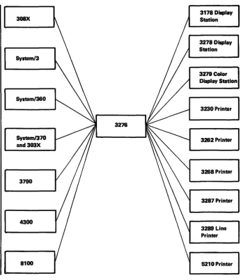
1-1. Host Control Unit and Device Combinations • . . . 1-2
1· 2. United States EBCDIC I/O Interface Codes for
3276 Unit and Attached Display Stations and
Terminal Printers . . . • . . . 14
1-3. United States ASCII I/O Interface Codes for 3276 Unit and Attached Display Stations and Terminal Printers . . . 1-5 14. Control Character I/O Codes .. ' . . . • • . . . . 1-6 1-5. Data Flow between Data Processing System and the 3276 . . . •• 1-7 1-6. Command Codes . . . • . . . •• 1-8 1-7. Write Control Character (WCC) . . . • 1-10 1-8. LU Type 2 Screen Size Bind Format . . . • 1-13 1-9. LU Type 3 Buffer Size Bind Format . . . • . . . 1-16 1-10. Attention ID (AID) ConfIgUrations . . . . • . • • . • . 1-19 1-11. Read State Transitions. . . • . . . • • . •. 1-24 1-12. Copy Control Character (CCC) . . . . • . . . • . . . . • 1-28 1-13. Buffer Transfers for 3276 Models 1 through 4 Copy Command Operation . . . • . . . • 1-29 1-14. Buffer Control Orders and Order Codes . . • . . . , 1-31 2-1. Buffer Location and Display Screen Character Position Relationships . . . • . . . 2-1 2-2. Buffer Addressing Layouts for 480-,960-,1920, 2560-, and 3440- Character Terminals . . • . . . 2-2 2-3. Example of Formatted Display . . . • • . . . 24
24. Field Attribute Character Bit Assignment . . . .• 2-6 2-5. Colors Derived from Field Attributes . . . • . . . • 2-7 2-6. Selector Light Pen . . . • . . . . 2-20 2-7. Sample Display Screen for Selector-light-Pen Operations . . . • . . . . • . 2-23 2-8. Magnetic Slot Reader (3276, 3278, and 3279 Attachments) . . . • . . . . • • 2-24 2-9. Attachment of Magnetic Reading Devices to 3276, 3278, and 3279 . . . , 2-24 2-10. 10-Character Set Used with Magnetic Slot Reader . . . 2-25 2-11. Magnetic-Stripe Format (MSR Using lo-Character Set) . . . • . • . 2-26 2-12. Operation of the Display with an Unformatted Screen (MSR Using 10-Character Set) . . • • . • . . . • 2-27 2-13. Operation of the Display with a Formatted Screen (Using 10-character Set), Example 1 . . . 2-28 2-14. Operation of the Display with a Formatted Screen (Using 10-character Set), Example 2 . . . .• 2-29 2-15. Relationship between Buffer Data and Printed Data .• 2-33 3-1. Remote Control Unit and Device Addressing • . • . . . 3-11 3-2. General Poll and Specific Poll, Sequence/Response Diagram • • • • • • • • • • • • • • • • • • • • • • • • • • • 3-12 3-3. '3276 CU Message Response to Polling or Read Modified Command . . . • . . . .• 3-14 34. Selection Addressing, Sequence/Response Diagram .. 3-16 3-5. Write-Type and Control-Type Commands, Sequence/Response Diagram . . • . . • • • • • • . • . • 3-18 3-6. Read-Type Commands, Sequence/Response Diagram. 3-20 3-7. Remote Status and Sense Byte Definitions - BSC •.. 3-23 3-8. Remote Error Status and Sense Responses - BSC. . . . 3-24 3-9. Remote 3276 BSC Status and Sense Conditions .••. 3-26 4-1. Establishing a Session with a 3276 . . • . . . • . . . 44
4-2. Device Addressing for SNA Terminals . . . • • 4-6 4-3. SNA Commands Supported by the 3276 . . • . . . . , 4-8 Page of GA18-2081-O As Updated 1 Feb 1982 By TNL GN18-2144 4-6. Summary of SNA Commands Sent. . . 4-22 4-7. Bracket/Chain - LU Type 2 Initiated (without Contention) .. . . . , . . . • . . , . 4-23 4-8. Bracket/Chain - Host Initiated (without Contention) . . . • . • . • . . 4-24 4-9. Bracket/Chain - Host/SLU Contention . . . 4-25 4-10. Signal from Host • . . . . • . . . 4-26 4-11. Shutdown/Shutdown Complete . . . . • . • . . . , 4-27 4-12. CANCEL, SLU Type 2 Sending . . • . . • , . . . . • , 4-28 4-13. RTR - LU Type lor LU Type 3 Send . . . 4-28 4-14. State Diagram for Session Ownership of Device . . . . 4-37 4-15. Logical Subsystem . . . 441
4-16. Automatic Disconnection Support by 3276 . . . . • . 448
4-17. Summary Table of LUSTATs . . . 4-56 5-1. Example of Four Fields and Attribute Bytes • . . . 5-2 5-2. Results of Keyboard and Field Combinations . . . 5-3 5-3. - Example of Attribute Specification . . • . . • . . . ,5-5 54. Bl9ck-Diagramming a Sequence of Panels . . . • . • 5-9 5-5. Sign-On Panel as Written Out on Layout Sheet. 5-10 5-6. Panel Layout, Including Attnoute and Cursor Positions . . . • 5-11 5-7. Laying Out Field Attnoutes . . . • . . . • 5-13 5-8. Text Items on Panel Layout Sheet . . . • • . . . . 5-14 5-9. Attributes . . . , . . . 5-15 5-10. Attribute Default Values . . . 5-16 5-11. Completed Order and Information, No SFAP Capability . . . 5-16 5-12. Buffer Control Orders and Order Codes . • . • . . . .. 5-17 5-13. Sign-On Procedure Panel with Buffer Addresses . . . . 5-20 5-14. Attribute Combinations in Hexadecimal . . . 5-21 5-15. Assembler Language Statements for Sign-On Panel .. 5-26 5-16. An Example of the RA Order. . . . • . . . . 5-27 5-17.
wee
Hexadecimal Codes . . . , . . . 5-29 5-18. Panel 1 of an Accounts Receivable Application •••. 5-31 5-19. Panel 2, Showing the Results of a Search on a Customer Name . . • . . . • . • . . . • 5-31 5-20. Panel 3, Showing the Customer's Open Invoices . . . • 5-32 5-21. Panel 4, Showing Use of the Calculator . • • . . . 5-33 5-22. Panel 5, Showing Selection of Invoices after Using the Calculater . . . • . . . , . . . • 5-34 5-23. Panel 6, Showing New Balance after Posting . . . 5-34' 5-24. Sign-On Panel with Operator's Input. . . 5-35 5-25. Input Data Sequence. . . • . . . 5-35 5-26. Defmition of Field for Selector Pen Operation . . . . .. 5-38 5-27. Sample Panel for Selector Pen or Cursor Select Detection . . . 5-39 5-28. Modifying an Existing Panel, Basic Panel . . . 5425-29. Existing Panel with Error Message . . . • . • . . . • 542
5-30. Panel Layout Changes for Error Message (Keyed to Text) . . . • . . . • • • . . 543
5-31. Error Message Panel with Serial Number Field Erased. . . • . . . . .. 544
5-32. Example of EUA Use . . . • . . . • 545
5-33. Sign-On Panel with Three Erased Fields . . . • 546
5-34. Erasing Multiple Fields with EUA . . . .. 546
5-35. Example of Data Entry Panel. . . . • . . . • 548
5-36. Data Entry Panel with Entered Data. . . • 548
5-37. Employee Data Panel . . . • . . . 549
5-38. Panel Defmed with Program Tab . . . • . • . . . . So-50
6-1. . Relationship of Screen Management to Telecommunications Management and
A-I. 3276 Operator Panel •.••.•••..••..••.•. A-I A-2. 3276 Operator Drawer Panel . . • • • • . . . . • • . • . A-I D-I. Diagram of APL/Text Devices ..••..••••.•.• D-I D-2. APL/Text Feature, I-Byte I/O Interface Codes
(3230/3268/3276/3278/3279/3287) • . . . • . . . . • 1>-3 D-3. APL/Text Feature, 2-Byte I/O Interface Codes
(3230/3268/3276/3278/3279/3287) •••••••••. D4 1>4. National Use Differences I/O Interface Code
(3178/3230/3268/3276/3278/3279/3287) • • • • • •• D-S D-5. Katakana/APL I-Byte I/O Interface Codes
(3230/3268/3276/3278/3279/3287) ••.•••••.• D-6
x
0-6. Katakana/ APL 2-Byte I/O Interface Codes
(3230/3268/3276/3278/3279/3287) •..•.••.•• D-7 D-7. Text Print I/O Interface Codes
(3262/3289) • • . . . • • • . • . . . • . • . • . • • • D-8
D-8. 87-Key Typewriter/ APL Keyboard . . . ' . . . .• 6 D-9
D-9. 88-Key Katakana Typewriter/APL Keyboard •...• D-IO D-IO. 87-Key Typewriter/Text Keyboard ••..••..••. D-11 E-1. Japanese Katakana EBCDIC I/O Interface Code
for 3276 Units with 3178, 3230, 3262, 3268,
3278,3279,3287 (with 3276 Attachment
Chapter 1. 3276 Control Unit and Data Streams
Introduction
The IBM 3276 Control Unit Display Station is one of the basic units of the 3270 Infor-mation Display System Family. Theo3276 offers the user a wide selection of components and configurations. Also available are a variety of features which improve perfonnance, provide additional operational capability, and pennit expansion of the display system. (The features are described in the publication IBM 3270 Information Display System: Configurator, GA27-2849.)
All models of the 3276 can be selected to form 3270 system configurations attachable to
I
System/360, System/370, 303X Processor, 308X Processor, System/3, 4300 Processor, 8100 Information System, and 3790 Communication System configurations as hostI
systems. (See An Introduction to the IBM 3270 Information Display System,GA27-2739, for possible system combinations.)
The 3276 is a table-top CRT display station and control unit used for displaying alphameric data up to a maximum of 3440 characters, and for entering data into, and retrieving data from, a host system. The 3276 can be ordered to control up to seven display stations and printers. The 3276 includes one self-contained display which allows a maximum 3276 cluster size of eight tenninals.
The base 3276 provides one additional port for attachment of either display stations or printers. Up to three additional teoninal adapters can be ordered. Each adapter has two ports which can attach display stations or printers in any combination. A keyboard is needed on every 3276.
The display station provides image display of data transmitted from the host system. A display station with an attached keyboard enables the user to enter, modify, or delete data on the display and to cause the revised data to be returned to the host system for storage or additional processing.
The 3276 can display up to 3440 characters per screen as follows:
• Models 1 and 11 display 960 characters.
• Models 2 and 12 display 1920 characters.
• Models 3 and 13 display 2560 characters.
• Models 4 and 14 display 3440 characters.
When operating in 3277-compatible format, the 3276 Modell will display 480 characters (40 characters per line), and Models 2, 3, and 4 will display 1920 characters (80
characters per line).
For EBCDIC and ASCII, the 3276 has a 94-character set (Plus space and null).
1·2
308X
Systam/3
System/360
3276
System/370 and303X
3790
4300
[image:11.612.174.520.53.455.2]8100
Figure 1·1. Host Control Unit and Device Combinationa
3178 Display Station
3278 Display Station
3279 Color Display Station
3230 Printer
3262 Printer
3268 Printer
3287 Printer
3289 Line Printer
5210 Printer
The 3276 Models 1,2,3, and 4 attach via modems and operate via BSC line protocol at 1200, 2000, 2400,4800, and 7200 bps. When the models are directly connected to a 3704/3705 Communications Controller, communication speed is limited to 1200 bps.
Models 11, 12, 13, and 14 attach via modems and operate via SOLC line protocol at 1200, 2000, 2400, 4800, 7200, and 9600 bps. When the models are directly connected to the 3704/3705 Communications Controller, communication speed is limited to 1200 bps.
Note: The 3276 Models 1, 2, 3, and 4 with the SDLC/BSC Switch/eature installed can also operate via SDLC protocol at the same communication line speeds as the Models 11, 12,13, and 14.
Models 11, 12, 13, and 14 communicate with the 8100 Infoonation System or the 4300 System via modems and an SOLC data link, a directly attached loop, or a data-link· attached loop. Models 1,2,3, and 4 (with the SDLC/BSC switch set to SDLC) can communicate with the 8100 system or the 4300 System via modems and an SOLe data link.
The printer provides a printed copy of data displayed at a display station or transmitted from the host system. (In this d'ocument, the 3230,3262,3268,3287,3289, and 5210 Printers are referred to as "teonina! printers.")
~
Interface Codes
Device Addressing
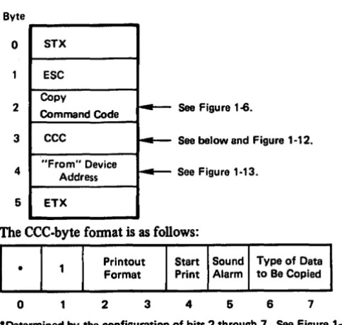
The 3276 Models 1,2,3, and 4 process the host-initiated BSC Copy command. The host-initiated Copy command is used to transfer buffer data from one device to another device via the 3276 to which both devices are attached. After accepting a Copy
command addressed to the "to" device, the 3276 initiates the data transfer from the "from" device. Upon transfer of the data to the 3276, the 3276 processes the data and transfers it to the "to" device.
In addition to processing the host-initiated Copy command, the 3276 (all models) also provides an operator-initiated local copy function, which pennits direct data transfer from a display station to a printer attached to the same 3276. The local copy function is initiated when the display station operator presses the print key on the display station keyboard. The printer selection is detennined by a print-control matrix (called a printer default matrix) in the 3276. The printer default matrix is determined by the physical attaclunent of the printers to the 3276 at power-on time. In this matrix, each display station is associated with the printer that has the next higher tenninal address. Printer assignment can be changed by use of the IDENT key on the 3178, 3276, 3278, or 3279 keyboard.
If the 3276 Models 11, 12, 13, and 14, or the 3276 Models 1,2,3, and 4 are equipped with the BSC/SDLC Switch feature and the switch is in the SDLC position, the host-initiated copy function is executed when the host issues a write-type command with the WCC print bit set to 1. Printer selection and servicing of the local copy request pro-ceed in much the same way as in the operator-initiated local copy function.
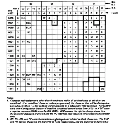
Data, commands, and orders transmitted between the control unit and the host system are in the fonn of interface codes. Two different codes are used in the United States: extended binary-coded decimal interchange code (EBCDIC) and American National Standard Code for Infonnation Interchange (ASCII). The EBCDIC codes are also used in the World Trade countries (ASCII is available only in the U.S.); refer to IBM 3270 Information System: ChIlracterSet Reference, GA27-2837, for details.
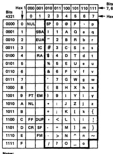
Figure 1-2 shows the United States EBCDIC interface codes for several control unit/ device combinations. Figure 1-3 shows the United States ASCII codes. Figure 14 shows the control character codes. Refer to Appendix E for the Katak,ana codes.
1-4
00 01 10 11 ~
Hex 1 00 01 10 11 00 01 10 11 00 01 10 11 00 01 10 11 ~
Bits
~
4567 0 1 2 3 4 5 6 7 8 9 A B C 0 E F ~
0000 0 NUL I SP &
-
{ } \ 00001 1 SBA I a j
-
A J 10010 2 EUA b k s B K S 2
0011 3 IC c I t C L T 3
0100 4 d m u 0 M U 4
0101 5 PT NL e n v E N V 6
0110 6 f 0 w F 0 W 6
0111 7 9 P x G P X 7
1000 8 GE SA h q Y H Q y 8
1001 9 EM SFE
I
, i r z I R Z 91010 A ¢ I I :
I
1011 B $ ,
#
1100 C FF DUP MF RA
<
• % @1101 0 CR SF ( )
-
,I
1110 E FM + ; > =
1111 F
sue
I.,
7 " EONotes:
1. Character code 8S8lgnments other than thOStllhown within all outlined artNl$ of thl, chart al'fJ undefined. If an undefined character code i, programmed, the character that will be di,played or printed i, a hyphen (-),. hex code 60 will be I'fJturned on a subsequent l'fJad operation. For control units with Configuration Support C Installed, undefined control codes from X'OO'to X3F' cause
a negative f81POfI8B (SNA) or an Op Chk (SSC). IBM l'fJ8eTVtJ8 the right to change at any time the character displayed or printed and the 110 Interlace codel'fJturned for an undefined character code.
2. CR, NL, EM, and FF control characters al'fJ displayed and printed as blank characters. The DUP and FM control characters are displayed al -; and -; I'fJ8pectively, and are displayed and printed 88
• and ,. when operating in mono-case mode.
3. Bits 0 and 1 are 8S8lgned for the following characters: AID, attribute, write control (WCC), copy control (CCC), CU and device addffl$$, buffer addffl$$, sense, and status. Bits 0 and 1 al'fJ B$$lgned 10 that each character can be represented by a graphic character within the ,olld outlined areas of the chart See Figure 1-4.
4. For BSC data-link control characters, ,ee Chapter 3. For the SCS control code, 8880ciated with the SNA Character String feature on terminal printers, see Chapter 2.
[image:13.608.133.537.53.472.2]5. When operating in mono-case mode, thelowerc889 alphabetic characters are displayed or printed B8 uppercase characters.
Figure 1-2. United States EBCDIC I/O Interface Codes for 3276 Unit and Attached Display Stations and Terminal Printers
Bits
0,1 2,3
Hex 1 000 001 010
Bits
~
4321 0 1 2
0000 0 NUL SP
0001 1 SBA I
0010 2 EUA "
0011 3 IC
#
0100 4 RA '$'
0101 6 %
0110 6 &
0111 7 ,
1000 8 (
1001 9 PT EM )
1010 A NL •
1011 B +
1100 C FF DUP
,
1101 0 CR SF
-1110 E FM
1111 F I
Notes:
011 100 101
3 4 6
0 @ P
1 A Q
2 B R
3 C' S
4 0 T
6 E U
6 F V
7 G W
8 H X
9 I Y
: J Z
; K [
<
L \= M ]
> N
,.
'1 0
-110 6
.
a b c d e f 9 h i j k I m n 0 111 7 P q r s t u v w x V z { I I } -- f4-Bits 7,6,6 Hex 01. Character code B88ignmentB other than those shown within all outlined areas of this chart are undefined. If an undefined character code Is programmed, the character that will be displayed or printed Is a hyphen (.),. code 20 will be returned on a subsequent read operet/on.
IBM reserves the right to change at any time the character displayed or printed and the lID interfaclTcodB returned for an undefined character code.
2. CR, NL, EM, and FF control characters are displayed and printed as blank characters.
The OUP and FM control characters are displayed as .. and;respectively, and are displayad and printed as • and ,. when operating in mono-case mode.
3. AID, attribute, write control (WCC), copy control (CCC), CU and devlcs addre88, buffer addf8$$, senre, and status characters are lJS8igned as specified in Figure 14 so that each character can be
represented by a graphic character within the solid outlined portion of this chart. 4. For BSC date-link control characters, leB Chapter 3.
6. When operating in mono-case mode,. the lowercase alphabetic characters are displayed or printed BI uppercBl8 characters.
Figure 1-3. United States ASCn I/O Interface Codes for 3276 Unit and Attached
[image:14.624.212.447.56.375.2]1-6
81ts2·7 Graphic EBCDIC ASCII 81ts2·7 Graphic EBCDIC ASCII
00 0000 SP 40 20 10 0000
.
60 2000 0001 A C1 41 10 0001 I 61 2F
00 0010 8 C2 42 10 0010 S E2 53
00 0011 C C3 43 ,10 0011 T E3 54
00 0100 0 C4 44 10 0100 U E4 55
00 0101 E C5 45 10 0101 V E5 56
00 0110 F C6 46 10 0110 W E6 57
00 0111 G C7 47 10 0111 X E7 58
00 1000 H C8 48 10 1000 y E8 59
00 1001 I C9 49 10 1001 Z E9 5A
1010 { 4 4A
-00 [
-
58 10 1010 10 1011 : (EBCDIC) , 6A 68 7C 2C00 1011 48 2E 10 1100 % 6C 25
00 1100
<
4C 3C 10 1101-
60 5F00 1101 ( 40 28 10 1110 > 6E 3E
00 1110 + 4E 28 10 1111 '1 6F 3F
1111
t
I 4F-00
J
-
2111 0000 0 FO 30
11 0001 1 F1 31
01 0000 & 50 28 11 0010 2 F2 32
01 0001 J 01 4A 11 0011 3 F3 33
01 0010 K 02 48 11 0100 4 F4 34
01 0011 L 03 4C 11 0101 5 F5 35
01 0100 M D4 40 11 0110 6 F6 36
01 0101 N 05 4E 11 0111 7 F7 37
01 0110 0 06 4F 11 1000 8 F8 38
01 0111 P 07 50 11 1001 9 F9 39
01 1000 Q 08 51 11 1010 : 7A 3A
01 1001 R 09 52 11 1011
#
7B 231010
t
J 5A-01 ]
50
-
11 1100@ 7C 40
11 1101 , 70 27
01 1011 S 58 24 11 1110 ::: 7E 3D
01 1100 * 5C 2A 11 1111 " 7F 22
01 1101 ) 50 29
01 1110 ; 5E 38
1111
t
-,
5F 01
"
-
5ENote: The characters above are used as attribute, AID, write control (WCC), copy control (CCC), CU and device addreS8, and buffer addreS8. They are a/so used B$ status and sense, except by the 3274 and 3276 when operating in BSe. When any of these characters is transmitted to the program, the CU assigns the appropriate EBCDIC code. If tranlmiaion is in ASCII, the CU translates the EBCDIC code to ASCII code prior to transmiaion.
To use this table to determine the hex code transmitted for an addreS8 or control character, first determine the values of bits 2-7. Select this bit configuration from the "Bits 2·7" column. The hex code that will be transmitted (either in EBCDIC or in ASCII) is to the right of the bit configuration.
Use this table also to determine equivalent EBCDIC and ASCII hex codes and their associated graphic characters.
[image:15.612.48.537.51.483.2]Graphic characters for the United States I/O interface codes are shown. Graphic characters might differ for particular World Trade I/O interface codes. Refer to IBM 3270 Information Disp/ay System: Character Set Reference, GA27·2837, for p086ible graphic differences when these codes are used.
Data Stream
Data Proceaing System
I
I Application
Program I I
I
I
I
I
I
b"y.tem Channel
The 3276 data stream consists of user-provided data, commands, and orders which are transmitted between the control unit and the host system (Figure 1-5). Control infor-mation, which governs the movement of the data stream, is also transmitted. The control units can differ as to the type of commands and/or transmission protocols employed.
Commands are issued to initiate such operations as the total or partial writing, reading, and erasing of data in a selected device buffer. Control commands initiate control unit and/ or teoninal operations not involved with data transfer (except for status informa-tion). Orders can be included in write data streams, either alone or intermixed with display or print data.
Two types of orders are available - buffer control orders and printer format orders. Buffer control orders are interpreted and executed as they are received by the control unit. They are used to pOSition, defme, modify, assign attributes on a field and character basis, and to format data being written to a display character buffer; to erase selected unprotected data in the buffer; and to reposition the cursor. Printer format orders are initially stored in the printer character buffer as data and are inter-preted and executed by the printer logic when encountered in the print operation.
The balance of this chapter describes the 3270 data stream. In-depth defmition and discussion of the 3270 data stream is provided in the publication IBM 3270 Information Display System, 3270 Data Stremn Programmer's Reference, GA23-00s9.
The 3276 can operate under SNA protocol using SDLC line disCipline. In the SNA/SDLC
environment, attached 3178s, 3278s, or 3279s function as LU type 2. The data stream RU
for a write-type command, for example, consists of the command code, buffer orders, and display data.
3178 Display, ~m
Remote
-Executes ~
3278 Display (except Model 6), 3279 Display, 3230 Printer, 3282 Printer. 3288 Printer. Channel
Commands ~
1,.4-TCU
~--~
3278 Control Unit Display Station
3287 Printer, 3289 Line Printer, or 6210 Printer
Executes 3270 ..
Commands (received t7.:22'222ZZ:~.;J
Modem In write data) I' ...
11,.1)
-IZZZZ:"~--
---1.1' ...
---1
~ r Buffor '
Stores
-~ Data
Buffer
Stores
Commands
1-8
The terminal printers attached to a 3276 can also function in BSC or SNA/SDLC protocol. When operating in SNA/SDLC protocol, the terminal printers function as LU type 3. When SCS is installed, the printer functions as an LU type 1. The terminal printers can also operate as local copy devices; that is, data may be sent to a printer(s) from a display station attached to the same 3276, which functions
in either BSC or SNA/SDLC discipline.
Three basic types of commands are used by the 3276:
1. Write commands, which are used to transfer data and orders from main s~orage to the 3276.
2. Read conunands, which transfer 3276 buffer data, keyboard key data, and, for remote configurations, status infonnation to main storage.
3. Control commands, which cause certain printer or display station operations.
Figure 1-6 lists the commands and associated codes that can be executed.by the 3276.
3276 Command EBCDIC ASCII
Hex Hex Graphic
Copy I F7 37 7
Erase All Unprotected 6F 3F ?
EraselWrlte F5 36 5
EraselWrite Alternate 7E 3D :=
Read Buffer F2 32 2
Read Modified F6 36 6
Read Modified AU2 6E 3E :
Write F1 31 1
I Applicable to 3276·1 through -4 only.
2 Applicable to 3276·11 through ·14 only.
Figure 1~. Command Codes
When a remotely attached 3276 is in operation, the rate at which data is transferred between the data processing system's main storage and the control unit depends on the type of transmission control unit and on the modems and communication facilities used. The 3276 accepts data from, and provides it to, the transmission control unit/communi. cation facility at the byte rate established by the transmission control unit/communication facility.
Write Commands
Write Command
Two write-type conunands, Write and Erase/Write, are used to load, fonnat, and selec-tively erase device buffer data. These conunands can also initiate certain device operations such as starting the printer, resetting the keyboard, and sounding the audible alann. Write and erase/write operations are identical except that Erase/Write causes complete erasure of the device buffer before the write operation is started. Thus, Erase/Write is used to load the buffer with completely new data, whereas Write can be used to modify existing buffer data. Because of this, the 3276 initiates a device-to-control unit buffer transfer before Write command operations, but not before Erase/Write command operations.
A third write-type command, Erase/Write Alternate, performs the erase/write function for the display stations and the terminal printers. It is also used to switch the display or printer into large screen or expanded print capacity mode.
The Erase/Write Alternate command is valid when sent to the 3276.
The bytes received by the 3276 for Write command operation consist of a command code, a write control character (WeC), and any orders and/or new buffer data needed to modify the existing buffer contents. Remotely attached 3276s also receive appropriate data link control framing. The sequence of bytes is as follows:
xxx
XXX
Any Write Command
WCC
--
Orders and/or"'" Buffer Data
~
XXX
}
Data Link Framing Characters (Remote Only).
- See Figure 1-6.
- See following text and Figure 1-7.
1-10
The minimum data stream following a Write command is a I-byte WCC. This is ensured because the byte count field of the write channel control word (CCW) must be set to a minhnum of 1 in' BSC operations, or else the command code is not sent. The minimum Write command data stream to a remote 3276 consists of framing characters (e.g., in BSC, STX, ESC, and ETX) and the command code. To be meaningful, a WCC byte should follow the command code; if the BSC data link control character ETX follows the command code, an all·zero default
wec
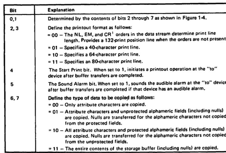
byte is generated by the control unit, and command execution is ended nonnally. An order or display/print data byte that immediately follows the command code is interpreted as a WCC by the control unit. The WCC byte fonnat isas
follows:Reset Printout Start Sound Key- Reset
-
Bit Format Print Alarm board Restore Bits MDTo
2 3 4 5 6 1-Determined by the configuration of bits 2 through 1. See Figure 1-4.
Figure 1·7 describes the function of each
wce
bit. When thewee
specifies an operation that does not apply to the selected device (for example, if the SoundAlarm
bit is set a,nd the selected device does not have the AudibleAlarm
feature), the specified opera· tion is ignored. When the WCC byte is followed by order or display/print data bytes, only the Reset MDT Bits function, if specified, is perfonned before the write operation; any other WCC function is deferred until all data is written and all orders are per-fonned.Bit Explanation
0 Determined by the contents of bits 1 through 1 as shown in Figure 1-4. 1 WCC reset bit.
2,3 Define the printout format, as follows:
1Z 00 - The NL, EM, and CR' orders in the data stream determine print line
length. Provides a 1320print position line when the orders are not present . .. 01 - Specifies 40-character print line.
D 10 - Specifies 64-character print line . .. 11 - Specifies 80-character print line.
4 Start Printer bit. When set to 1, initiates a printout operation at completion of the write operation.
5 The Sound Alarm bit. When set to 1, sounds the audible alarm at the selected device at the end of the operation if that device has an audible alarm. 6 The Keyboard Restore bit. When set to 1, restores operation of the keyboard
by resetting System Lock or Wait symbol on 3178, 3216, 3218, or 3279 displays. It also resets the AID byte at the termination of the I/O command. 7 Reset MDT bits. When set to 1, all MDT bits in the selected devices' existing
buffer data are reset before any data is written or orders are executed.
1 The CR order is applicable to the termina' printers only.
Orders and buffer data can follow the WCC character. (Orders are described later in
this chapter, following the "Commands" description.) Buffer data can be written into
any specified location of the buffer without erasing or modifying data in the other buffer locations. Data characters are stored in successive buffer locations until an order is encountered in the data stream which alters the buffer address, or until all
the data has been entered. During the write operation, the buffer address is advanced one location as each character is stored.
The buffer location where data entry starts depends upon the following considerations:
1. The starting location may be specified by a Set Buffer Address order that follows the WCC. (This order is described later in this chapter under "Orders.")
2. The starting location will be the buffer address containing the cursor if the Write command is not chained or if it is chained from a Copy or Erase All Unprotected command.
3. The starting location will be the current buffer address if the Write command is chained from a Read or another Write command.
The formatting and placement of write data and the modification of existing buffer data are described under "Orders."
Programming Notes:
1. If the commands are being chained, the Write or Erase/Write command with the Start Print WCC bit set must be the last command in the chain. If not, remote control units perform the print operation and abort the next command.
2. The Printout Format bits are honored only if the Start Print bit is set in the same
weco
3. In remote operations, if a Write command that includes data is chained from a pre-vious Write command, a Set Buffer Address (SBA) order should immediately follow the
wee
to defme the starting location at which data entry is to start; this permits recovery in case of an error condition that requires retransmission of that data.Erase/Write Command
Erase/Write Alternate Command
1-12
Execution of the Erase/Write command perfonns two operations: an erase operation and a write operation. The erase operation clears the entire device buffer to nulls, positions the cursor to character location 0, and resets the buffer address to O.
Erase/Write then perfonns the write and WCC operations in the same manner as a Write command. If no WCC is sent, the Erase/Write command wi)) not erase the buffer.
An Erase/Write command can also return a display or printer to the default screen size or character print capacity (as described under "Erase/Write Alternate Command").
The display stations and the terminal printers with a capacity of 960 characters can function as 480-character devices; 1920-,2560-, and 3440-character displays and printers can function as 1920-character devices.
For the 3276 BSC, a unique instruction is required from the application program to enable a display or printer to function at greater than 480- or 1920-default-character capacity. The Erase/Write Alternate command is used to switch a display station's screen size or a terminal printer's print capacity to the alternate size indicated by the display model number or specified for the printer as follows:
3230 and 3287 and Default
3178 3288 3282 3276 3278 3279 3289 5210 Character
Model Modal Model Model Model Model Model Model Capacity
-
2 13 1,11 1-
1,2 G01,G02 480C1,C2 2 13 2,12 2 2A,28 1,2 G01,G02 1920
-
2 13 3,13 3 3A,38 1,2 G01,G02 1920-
2 13 4,14 4-
1,2 G01,G02 1920Note: For SDLe machines, the default and the alternate character capacity are defined by the BIND parameter. Thus, the default and the alternate can be exchanged.
Alternate Character Capacity
960
1920
2660
3440
The Erase/Write Alternate command also operates as an Erase/Write command. Once the display or printer is placed in alternate mode, operation continues in alternate mode until: the operator presses the CLEAR, SYS REQ (SNA only), or TEST key; or until an Erase/Write command is received, the SNA session is unbound, power fails at the control unit, display, or printer; or a system reset sequence occurs. Only these con-ditions return the display or printer to the default-value screen-size or character print capacity. For the 3276 SNA, the Erase/Write Alternate and Erase/Write commands are used to switch a display screen size, or a print capacity to alternate size, or vice versa, according to Bind parameter defInition.
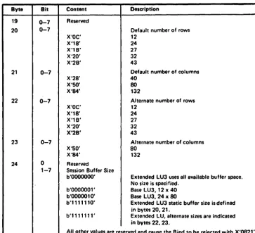
A 3178, 3276, 3278, or 3279 display operating as an LU type 2 requires the format shown
in Figure 1-8 as part of the bind operation.
If an Erase/Write Alternate command is received while bound, it is processed as a normal Erase/Write command. No state change occurs within the display. Default screen sizes are as follows:
3178 3278 3279 Default Screen Size Assumed with Model Model Model Byte 24
=
b'OOOOOOO'1 480 (12 x 40) Cl,C2 2 2A,2B 1920 (24 x 80) 3 3A,3B 1920 (24 x 80) 4 1920 (24 x 80)
Byte 81t Model Con1llnt Description
20 0-7 Default number of rows
1 X'01' - X'OC' 1-12 2 X'01' - X'1B' 1-24 3 X'01' - X'20' 1-32 4 X'01' - X'2B' 1-43 5 X'01' - X'1B' 1-27
21 0-7 Default number of columns
1 X'28' 40
1-5 X'SO' 80
5 X'84' 132
22 0-7 Alternate number of rows
1 X'01' - X'OC' 1-12 2 X'01' - X'18' 1-24 3 X'01' - X'20' 1-32 4 X'01' - X'2B' 1-43 5 X'01' - X'1B' 1-27
23 0-7 Alternate number of columns
1 X'28' 40
1-5 X'SO' 80
5 X'84' 132
24 0-7 Session screen size
0 All Reserved reserved
1-7 1-5 b'OOOOOOO' Base default (12 x 40 or 24 x 80) 1 b'OOOOOO1' Base Model 1 default (12 x 40) 2-5 b'OOOO010' Base Model 2 default (24 x 80) 1-5 b'111 1110' Extended default (size specified in bytes
20 and 21)
1-5 b'1111111' Extended alternate (size specified in bytes 22 and 23)
Note: Row values ourslde these ranges and column values other than those listed cause the Sind to be rejected with X'0821'.
1-14
Only a Modell display can be bound as b'OOOOOOl', a base LU type 2 with a 12 x 40 character screen. This coding of the Bind image is rejected with X'082 1 ' on Models 2, 3,4, and 5.
A Model 2, 3,4, and 5 display can be bound as b'OOOOOlO', a Base LU type 2 with a 24 x SO character screen. This Bind fonnat, if used for a Modell display, causes the Bind to be rejected with X'OS2l'.
When operating with a screen size of 4S0 characters, sequential buffer addresses map to the 12 x 40 screen fonnat in row major order. When operating in other screen sizes, sequential buffer addresses map to the defmed screen fonnat in row major order (Appendix B).
Byte 24 mllst be coded X'7E' or X'7F' to use displays in large-screen mode (2560 and 3440 characters) during the LU-LU session.
When bits 1 through 7 of byte 24 are coded X'7E', the screen size of the device is defmed in bytes 20 and 21 of the Bind image, and bytes 22 and 23 are ignored. The device operates with the defmed screen size during the entire session. An Erase/Write Alternate command is accepted by the device but is interpreted as an Erase/Write command. No state change occurs, and the screen size remains as defmed in bytes 20 and 21 of the Bind image. Valid codings of bytes 20 and 21 are as follows:
Modell Model 2 Model 3 Model 4
Byte Hex ~'OC' ~'IS' ~'20' ~'2B'
20 Row ~12 ~24 ~32 ~43
Byte Hex X'2S' X'50' X'50' X'50' X'50'
21 Col 40 SO SO SO SO
If the Bind specifies an invalid number of columns, or if the number of rows is greater than the maximum row specified ( above) for each model, the Bind will be rejected. Buffer wrap will occur at the end of the row specified in byte 20.
When bits 1 through 7 of byte 24 are coded b'Ollllll', a dynamic switch can be made during the session between a default screen size and an alternate screen size. When byte 24 is coded in this way, bytes 20 through 23 defme the default and alternate screen sizes.
Valid codings of these bytes are as follows:
Modell Model 2 Model 3 Model 4
Bytes Hex ~'OC' ~'lS' ~'20' ~'2B'
20 and Row ~12 ~4 ~2 ~43
22
Byte Hex X'2S' X'50' X'50' X'50' X'50' 21 and Col 40 SO SO SO SO 23
The Bind is rejected if an invalid number of columns is coded in the Bind image or if
the number of rows is greater than the maximum row value shown for each model (above). When in alternate-size mode, the display will wrap at the end of the row specified in byte 22 of the Bind image. When in default-size mode, the screen will wrap at the end of the row specified in byte 20 of the Bind image.
Once the Bind has taken place, the display is cleared and set to the default screen size and format. Request/Response Units (RUs) that contain SBA, RA, or EUA orders with addresses out of the range of the default screen size are rejected with -RSP (1005) (address out of range) response. Data will wrap at the default screen boundary whether input by the operator or from the outbound data stream, and wrapping will occur at the default screen boundary as dermed for all other 3270 operations (for example, Erase All Unprotected, Read Buffer).
The Erase/Write Alternate command dynamically switches the display to the specified alternate screen size. Note that, on a Model 2 display, the Erase/Write Alternate command performs no meaningful fv.nction.
If bound to dynamically switch, the device assumes the characteristics of a display with the alternate screen size, upon receipt of an Erase/Write Alternate command. RUs that contain SBA, RA, or EUA orders that have addresses out of the range of the vali