This content has been downloaded from IOPscience. Please scroll down to see the full text.
Download details:
IP Address: 161.112.232.221
This content was downloaded on 27/05/2014 at 13:53
Please note that terms and conditions apply.
CLARA conceptual design report
View the table of contents for this issue, or go to the journal homepage for more 2014 JINST 9 T05001
(http://iopscience.iop.org/1748-0221/9/05/T05001)
2014 JINST 9 T05001
PUBLISHED BYIOP PUBLISHING FORSISSAMEDIALAB
RECEIVED:January 21, 2014
ACCEPTED:March 25, 2014
PUBLISHED:May 9, 2014
TECHNICAL REPORT
CLARA conceptual design report
J.A. Clarke,a,b,∗D. Angal-Kalinin,a,bN. Bliss,aR. Buckley,a,bS. Buckley,a,b R. Cash,a
P. Corlett,a,bL. Cowie,a,bG. Cox,aG.P. Diakun,a,b D.J. Dunning,a,bB.D. Fell,a
A. Gallagher,a P. Goudket,a,b A.R. Goulden,a,b D.M.P. Holland,a,b S.P. Jamison,a,b
J.K. Jones,a,bA.S. Kalinin,a,b W. Liggins,a,bL. Ma,a,b K.B. Marinov,a,bB. Martlew,a
P.A. McIntosh,a,bJ.W. McKenzie,a,bK.J. Middleman,a,b B.L. Militsyn,a,b A.J. Moss,a,b
B.D. Muratori,a,bM.D. Roper,a,bR. Santer,a,b Y. Saveliev,a,bE. Snedden,a,b
R.J. Smith,a,bS.L. Smith,a,b M. Surman,a,bT. Thakker,a,bN.R. Thompson,a,b
R. Valizadeh,a,bA.E. Wheelhouse,a,b P.H. Williams,a,bR. Bartolini,c,d I. Martin,c
R. Barlow,e A. Kolano,eG. Burt,b,f S. Chattopadhyay,b,f,g,hD. Newton,b,gA. Wolski,b,g
R.B. Appleby,b,hH.L. Owen,b,hM. Serluca,b,h G. Xia,b,hS. Boogert,iA. Lyapin,i
L. Campbell,jB.W.J. McNeilj and V.V. Paramonovk
aSTFC Daresbury Laboratory, Sci-Tech Daresbury, Warrington, U.K.
bCockcroft Institute, Sci-Tech Daresbury, Warrington, U.K.
cDiamond Light Source, Oxfordshire, U.K. dJohn Adams Institute, University of Oxford, U.K.
eUniversity of Huddersfield, U.K.
fUniversity of Lancaster, U.K. gUniversity of Liverpool, U.K.
hUniversity of Manchester, U.K.
iJohn Adams Institute at Royal Holloway, University of London, U.K. jUniversity of Strathclyde, U.K.
kInstitute for Nuclear Research of the RAS, Moscow, Russian Federation
E-mail:[email protected]
ABSTRACT: This report describes the conceptual design of a proposed free electron laser test
fa-cility called CLARA that will be a major upgrade to the existing VELA accelerator test fafa-cility at Daresbury Laboratory in the UK. CLARA will be able to test a number of new free electron laser schemes that have been proposed but require a proof of principle experiment to confirm that they perform as predicted. The primary focus of CLARA will be on ultra short photon pulse generation which will take free electron lasers into a whole new regime, enabling a new area of photon science to emerge.
KEYWORDS: Accelerator modelling and simulations (multi-particle dynamics; single-particle
dy-namics); Beam dynamics; Accelerator Subsystems and Technologies; Instrumentation for FEL
2014 JINST 9 T05001
Contents
1 Introduction and motivation 5
2 Benefit to VELA 11
3 FEL design 14
3.1 Introduction 14
3.2 Parameter selection 15
3.3 Operating modes 16
3.3.1 Seeding mode 16
3.3.2 SASE mode 17
3.3.3 Ultra-short pulse mode 17
3.3.4 Multibunch mode 17
3.3.5 Electron beam stability requirements 18
3.4 FEL layout 19
3.4.1 Modulator section 19
3.4.2 Radiator section 20
3.4.3 Afterburner 21
3.5 FEL schemes 21
3.5.1 SASE 21
3.5.2 Generation of short pulses 22
3.5.3 Improving temporal coherence 27
3.5.4 Afterburner schemes 33
3.6 Scaling to short wavelengths 33
4 Accelerator design 35
4.1 Layout overview 35
4.1.1 Phase space linearisation 36
4.1.2 Energy at magnetic compressor 36
4.1.3 Variable bunch compressor 38
4.1.4 Diagnostic sections 38
4.2 Beam dynamics 40
4.2.1 Electron source 41
2014 JINST 9 T05001
4.2.3 Other operating modes 42
4.3 Tolerance studies 42
4.3.1 Beam based alignment strategy 43
5 Accelerator systems 46
5.1 Electron source 46
5.1.1 Baseline electron source 47
5.1.2 Advanced electron source 47
5.2 Radio frequency systems 51
5.2.1 Linac accelerating structures 52
5.2.2 High power RF systems 54
5.2.3 Low level RF system 55
5.3 Electron beam diagnostics 59
5.3.1 Bunch charge monitors 59
5.3.2 Strip line BPMs 59
5.3.3 Cavity BPMs 60
5.3.4 Screen diagnostic systems 60
5.3.5 Beam arrival monitors 61
5.3.6 Bunch compression and temporal profile monitors 61
5.3.7 Laser Arrival Monitors 61
5.4 FEL output diagnostics 62
5.4.1 Introduction 62
5.4.2 Spectral diagnostics 63
5.4.3 Temporal diagnostics 64
5.4.4 Photon flux and pulse energy monitoring 65
5.5 Optical timing and synchronisation 66
5.5.1 Synchronisation targets 66
5.5.2 Timing system architecture 66
5.5.3 RF Master Oscillator 68
5.5.4 Laser Master Oscillator 68
5.5.5 Optical clock distribution 68
5.5.6 Laser-to-laser synchronisation 68
5.5.7 Beam Arrival Monitors 69
5.5.8 Laser Arrival Monitors 69
5.5.9 Referencing of LLRF 69
5.6 Lasers 69
5.6.1 Seed lasers for FEL modulation 69
5.6.2 Photoinjector laser system 72
5.6.3 Lasers for FEL photon diagnostics 72
5.6.4 Laser synchronisation 73
5.7 Undulators 73
5.8 Control system 74
2014 JINST 9 T05001
5.8.2 Architecture 75
5.8.3 Controls hardware 75
5.8.4 Timing and synchronisation system 76
5.8.5 Interlock systems 76
5.8.6 Feedback systems 77
6 Radiation safety 78
6.1 Shielding requirements 78
6.1.1 Radiological classification of areas 78
6.1.2 Source and material data 78
6.1.3 Shielding calculations 79
6.2 Personnel safety system 80
6.2.1 Purpose 80
6.2.2 Design requirements 80
6.2.3 Implementation 81
7 Potential upgrades and future exploitation 82
7.1 Plasma accelerator research 82
7.2 Ultrafast Electron Diffraction 83
7.3 Compton photon production 84
7.4 Dielectric Wakefield Acceleration 84
7.5 Nonequilibrium electron rings 85
7.6 Exotic storage ring concepts 86
7.7 Industrial exploitation 86
Acknowledgments
2014 JINST 9 T05001
Chapter 1
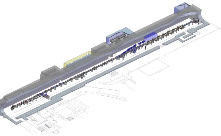
[image:6.595.106.486.280.515.2]Introduction and motivation
Figure 1.1.CLARA — the Compact Linear Accelerator for Research and Applications.
2014 JINST 9 T05001
Single-Spike SASEEmittance Spoiling Emittance Spoiling
Superradiant Pulse Shortening Laser Slicing
Mode-Locking + Modelocked Afterburner
Pre-bunching + Short Radiator
Laser Seeding
Self Seeding
Cavity FELs - RAFEL and X-FELO
Harmonic Cascades and Echo-Enabled Harmonic Generation High-Brightness SASE
HHG Seeding
U
L
T
R
A
S
H
OR
T
P
U
L
S
E
S
T
E
M
P
OR
A
L
C
OH
E
R
E
NC
E
Multicolour FELs Mode-Locking
Echo-Enabled Harmonic Generation
TA
IL
OR
E
D
P
U
L
S
E
S
All Seeding
Tapering Cavity FELs - RAFEL and XFELO
S
TA
BI
L
IT
Y
&
P
O
W
E
R
IN ROUTINE USE or WELL TESTED
PROOF-OF-PRINCIPLE
or NOT TESTED
Figure 1.2.Schematic representation of the FEL landscape in terms of potential improvements to particular output properties against progress to date.
Accelerator for Research and Applications), a dedicated flexible FEL Test Facility, which will be able to test several of the most promising of the new schemes. Figure1.1shows a three-dimensional representation of CLARA. The successful proof of principle demonstration with CLARA will be a vital stepping stone to the implementation of any new scheme on an existing or planned FEL facility.
2014 JINST 9 T05001
in figure 1.2. It is clear that whilst significant progress has been made recently in making FELsoperational, there are many major areas where the potential of FELs remains untapped. We aim to release this potential to open up further new fields of science for investigation and exploitation.
Our vision for CLARA is that it should be dedicated to the production of ultra-short photon pulses of high-brightness coherent light. Existing X-ray FELs are already capable of generating pulses of light that are only tens of femtoseconds in duration (tens of thousands of optical cycles) but FEL experts have proposed several schemes which have the potential to generate pulses that are two or three orders of magnitude shorter than this (hundreds or tens of attoseconds) [7–15] and a recent paper has even proposed a novel idea for sub-attosecond pulse generation from a FEL (a few optical cycles) [16]. The science which is enabled by ultra-short photon pulses was described in detail in the NLS Science Case [17] and reviews of science carried out using attosecond pulses are also available [18–20]. Many exciting applications of attosecond pulses have already been demonstrated, including coherent X-ray imaging, femtosecond holography, real-time observations of molecular motion and capturing the movement of electrons in atoms and molecules. Attosecond X-ray science could revolutionise how we understand and control electron dynamics in matter.
In order to achieve this vision for ultra-short pulse generation, CLARA must be able to imple-ment advanced techniques, such as laser seeding, laser-electron bunch manipulation, and femtosec-ond synchronisation. These can only be achieved by developing a state-of-the-art accelerator with the capability to drive current FEL designs. CLARA is therefore of direct relevance to the wider international FEL community and will also ensure that the UK has all the skills required should it choose to develop its own future FEL facility. This underpinning foundation requirement is shown in figure1.3.
In detail the goals, opportunities and benefits of CLARA will be:
• Proof-of-principle demonstrations of ultra-short ‘attosecond’ photon pulse generation (of order of the coherence length or less, typically less than 100 optical cycles) using schemes which are applicable to X-ray FELs (such as laser slicing, mode locking, or single spike Self-Amplified Spontaneous Emission (SASE)) and with extreme levels of synchronisation.
• The ability to test novel schemes for increasing the intrinsic FEL output intensity stabil-ity, wavelength stabilstabil-ity, or longitudinal coherence using external seeding, self seeding or through the introduction of additional delays within the radiator section.
• The ability to generate higher harmonics of a seed source using Echo Enabled Harmonic Generation (EEHG), High Gain Harmonic Generation (HGHG), or other novel schemes.
• The generation and characterisation of very bright (in 6D) electron bunches and the subse-quent manipulation of their properties with externally injected radiation fields, and the testing of mitigation techniques against unwanted short electron bunch effects.
tech-2014 JINST 9 T05001
Cathode Preparaon
Temperature Stability
Simulaon Codes
Underpinning Infrastructure
Vibraon Control
Environment Control
FEA Modelling
Vacuum Technology Transverse &
Longitudinal Diagnoscs
Photoinjector Laser
Normal Conducng RF Systems
Magnets and Undulators
Digital Low Level RF
Timing System
RF & Laser Master Clock Bunch
Compression Feedback Systems
Feed Forward Systems
RF Phase and Amplitude
Control
Trajectory Straightness
Accurate Alignment Transverse
Matching to FEL
High Peak Currents Energy Seed High Pulse
Laser
Long and Short Term
Stability
Low Emiance Electron Bunches Laser and
Electron Overlap
Electron Energy Modulaon with External Fields
Synchronisa-on of Laser & Electrons
Low Bunch
Timing Jier Harmonic Generaon
Single-Shot
FEL Photon Diagnoscs
Laser Seeding
ULTRA-SHORT PULSE GENERATION
U
N
D
E
RP
IN
N
IN
G
RE
Q
U
IRE
ME
N
T
S
U
LT
IMA
T
E
G
O
A
L
2014 JINST 9 T05001
niques. The potential to test the new generation of plasma-based accelerators as drivers ofFELs is also a significant consideration.
• The enhancement of VELA (Versatile Electron Linear Accelerator) [21], in terms of energy, beam power, and repetition rate, enabling additional industrial applications of electron beams that are currently excluded.
• A flexible, high quality, electron test accelerator available to the entire UK accelerator com-munity on a proposal-driven basis, enabling wide ranging, high impact accelerator R&D.
• The development and retention of vital skills within the UK accelerator community, includ-ing providinclud-ing excellent opportunities for attractinclud-ing the best PhD students and early stage researchers to work on a world class accelerator test facility.
• The possibility to use the high quality bright electron beam for other scientific research ap-plications such as ultra-fast electron diffraction experiments, plasma wakefield accelerators (as a witness bunch or a drive bunch), as the drive beam for a Compton scattering source of X-rays or gamma photons, and for other novel acceleration schemes such as dielectric wakefield accelerators and exotic storage rings.
We recognise the dynamic nature of FEL research and aim not just to demonstrate and study the novel concepts of today but also be well positioned to prove the novel concepts of tomorrow. For these reasons we have planned a number of different CLARA operating modes, each of which is designed to be appropriate for a different class of FEL experiments. The complete set of experi-ments discussed in this design report impacts on every area of the future FEL landscape presented in figure1.2. This flexibility of approach also extends to advanced technological aspects, such as retaining the ability to implement and test alternative RF systems in the future, for example C-band linac structures or even superconducting RF cavities, as required by the needs of the UK accelerator programme.
CLARA will be well placed to test emerging ideas for fifth generation light sources based on laser or electron driven plasma accelerators, such as those put forward by the FACET-II pro-posal [22]. The experimental testing of such advanced ideas, that scale well to larger projects, can result in leaps forward in capability.
The ability to simulate coherent light sources driven by plasma accelerators requires different computational models from those used to simulate light sources driven by conventional accelera-tors. A new simulation code has been developed by ASTeC in collaboration with researchers at the University of Strathclyde [23]. This is the only such code currently available and is generating significant international interest resulting in collaborations developing with international groups that wish to use both laser and electron beam driven plasma accelerators as FEL drivers.
These collaborations offer the potential for CLARA to develop into an international focal point for such research. The embedded excellence of ASTeC staff in the design of electron beam trans-port systems and start-to-end modelling capability would ensure that any plasma driven research towards a FEL would be internationally leading.
2014 JINST 9 T05001
CLARA. We believe that within 3 years of funding we could procure and install all of theequip-ment and commence beam commissioning.
International Context
Currently there are only four dedicated single pass FEL test facilities worldwide, one in the US (NLCTA), one in Asia (SDUV-FEL) and two in Europe (SPARC and MAX). We have assessed the capabilities and programmes of each of these facilities in turn and have confirmed that CLARA will offer unique capabilities and have a complementary programme to the other test facilities.
The NLCTAat SLAC is a low energy (120 MeV) test accelerator deliberately focussing on near term Research and Development (R&D). The main goal of this facility is the development and optimization of EEHG for the improvement of temporal coherence, indeed this facility was the first to demonstrate EEHG experimentally. The primary objective now appears to be the establishment of very high order harmonic generation with the EEHG scheme.
The SDUV-FELin Shanghai is the only dedicated test facility in Asia. They first observed SASE lasing in 2009 and this has been followed by seeded FEL experiments, EEHG, and other techniques for generating high harmonics from a seed laser, such as HGHG.
TheSPARCtest FEL at Frascati currently operates at 150 MeV with a planned upgrade to take it to 250 MeV. SASE lasing has been demonstrated and characterised, and direct High Harmonic Generation (HHG) seeding is being studied. SPARC has also carried out some short pulse experi-ments including energy chirped electron beams and undulator tapering and seeded superradiance.
The MAX-lab test FEL in Sweden will close at the end of 2013 after carrying out a final experiment exploring seeding by an HHG source at lower harmonics.
In summary, there are currently four FEL test facilities with similarities to CLARA. Improved temporal coherence using various seeding techniques dominate the programmes but one of the facilities has also carried out some promising experiments aimed at short pulse generation.
2014 JINST 9 T05001
Chapter 2
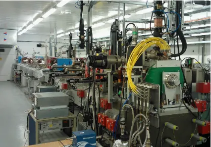
[image:12.595.87.513.281.578.2]Benefit to VELA
Figure 2.1.Photograph of the existing VELA facility at Daresbury Laboratory.
2014 JINST 9 T05001
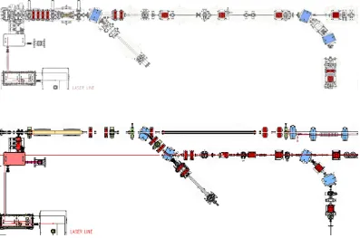
Figure 2.2. Engineering layouts of (top) the existing VELA facility and (bottom) VELA and the front end of CLARA once CLARA is fully installed.
commissioning and enabling accurate alignment of individual components on each module. Sec-ond, CLARA will be permanently installed parallel to VELA, spaced approximately one meter from the current VELA beam axis. This will mean that, with careful scheduling of installation activities, VELA will be able to continue to operate for users in parallel with CLARA installation. Indeed, the majority of CLARA is well away from VELA and this can be installed simultane-ously to VELA operations with no disruption at all. There will, of course, have to be a scheduled shutdown of VELA for final installation which will include: the reconfiguration of the radiation shielding into a single tunnel; the transfer of the photoinjector gun cavity across to the CLARA front end, along with modifications to the associated RF waveguide and photoinjector laser trans-port systems; breaking of the VELA machine vacuum to join the two facilities together with a short dogleg electron beam transport line between the CLARA beam axis and the existing VELA axis. This last aspect is another deliberate design choice which will mean that the VELA user areas will benefit from enhanced electron beam parameters post-CLARA installation.
2014 JINST 9 T05001
beam time. However, if the user demand for both facilities cannot be met, it would be relatively2014 JINST 9 T05001
Chapter 3
FEL design
3.1 Introduction
As discussed in chapter1 CLARA has been designed to be a dedicated flexible FEL test facility, which will be able to test several of the most promising of the new FEL schemes. The successful proof of principle demonstration with CLARA will be a vital stepping stone to the implementation of any new scheme on an existing or planned FEL facility.
In this chapter we discuss the main parameters for CLARA, before detailing a number of different CLARA operating modes each of which is designed to be suitable for a different class of FEL experiments. We then summarise the layout of the FEL systems before giving details of a selection of the FEL schemes we will be able to study on CLARA, including some predictions of the FEL output properties. We broadly divide the research topics into two main areas, each of which is intended to demonstrate new schemes for the improvement of FEL output beyond that available from the SASE process [25,26]. The first area is the generation of ultra-short pulses and the second area is improvement of temporal coherence. The physics of the FEL mechanism is not described in this report but is covered in a number of texts [27–29]. A number of review articles give a clear overview of the worldwide FEL status and future prospects [30–32].
CLARA has been designed and optimised so that the FEL wavelengths are in the visible and VUV. This has tremendous advantages for the operation of the FEL and diagnosis of the output. Our emphasis for the short pulse schemes is to generate pulses with as few optical cycles as possible with durations of the order of, or shorter than, the FEL cooperation length. These are our figures of merit and we aim to study the essential physics of the schemes which can often therefore be independent of the FEL wavelength.
2014 JINST 9 T05001
3.2 Parameter selection
The wavelength range chosen for the CLARA FEL is 400–100 nm, appropriate for the demonstra-tion of advanced FEL concepts on a relatively low energy accelerator. Key drivers for this choice are the availability of suitable seed sources for interacting with the electron beam, as required by many of the FEL topics we propose to study, and the availability of single shot diagnostic tech-niques for the characterisation of the FEL output.
We propose to study short pulse generation over the wavelength range 400–250 nm, where suitable nonlinear materials for single shot pulse profile characterisation are available. For schemes in this regime it is often necessary to produce a periodic modulation in the properties of the elec-trons along the bunch such that it can be arranged (using a variety of methods, depending on the scheme) that only some sections of the beam can lase. Often the scale length of each independent FEL interaction is given by the slippage in one gain length, known as the cooperation lengthlc, so
the modulation of the electron bunch properties should have a periodλM significantly longer than
this to enable an independent temporally-separated interaction for each period of the modulation. This means we requireλMlc. For the lasing wavelength range 400–250 nm for the short pulse
schemes this leads to the requirement that to cover most of the research topics the modulating laser should have wavelengthλ'20–50µm with the possibility of extending the wavelength to 120µm
later on.
For schemes requiring only spectral characterisation (for example producing coherent higher harmonics of seed sources, or improving the spectral brightness of SASE) the operating wavelength range will be 266–100 nm, with the possibility of output down to 80 nm at a later stage. For these schemes the most appropriate seed source (if required) is an 800 nm Ti:sapphire laser from which we can generate coherent harmonics up to the 8th harmonic, or 10th harmonic later on.
To operate at shorter wavelengths than 80 nm would currently offer little advantage, but many complications. The wavelength would in fact have to be significantly shorter than 80 nm to enable pulse profile characterisation and this would have to be done using photoionisation in gases as the nonlinear medium for the cross-correlation. Such a technique is complex and would not provide single-shot measurements, so is not acceptable. The photon diagnostic beamlines would also be more complex and require more floor space because low incidence angle optics would be necessary. Finally, the CLARA energy would need to be upgraded and the undulator beamline extended.
The required electron beam energy and undulator parameters depend on the required tuning range. The FEL wavelengthλris given by
λr=
λw
2γ2
1+K
2
2
whereλwis the period of the FEL undulator andγ is the electron energy in units of its rest mass.
2014 JINST 9 T05001
and a tuning range of 400–100 nm, this uniquely defines the required electron beam energy to beE=228 MeV and the undulator period to beλw=27 mm. However, we have designed the CLARA
accelerator to provide a maximum beam energy of 250 MeV. This allows sensible contingency in three areas. First, it allows the full wavelength tuning range to be achieved at a slightly reduced linac gradient. Second, it allows the linac cavities to be operated further off-crest for added flexi-bility. Third it allows us to push the FEL wavelength to around 80 nm with only a slight reduction in undulator parameter enabling us to generate even higher harmonics of the seed sources.
Table 3.1.Main parameters for CLARA operating modes.
Operating Modes
Parameter Seeding SASE Ultra-short Multibunch
Max Energy (MeV) 250 250 250 250
Macropulse Rep Rate (Hz) 1–100 1–100 1–100 1–100
Bunches/macropulse 1 1 1 16
Bunch Charge (pC) 250 250 20–100 25
Peak Current (A) 125–400 400 ∼1000 25
Bunch length (fs) 850–250 (flat-top) 250 (rms) <25 (rms) 300 (rms)
Norm. Emittance (mm-mrad) ≤1 ≤1 ≤1 ≤1
rms Energy Spread (keV) 25 100 150 100
Radiator Period (mm) 27 27 27 27
3.3 Operating modes
The approach we have adopted is to design a flexible, well-diagnosed facility for testing a variety of advanced FEL concepts. This flexibility will be built into the accelerator itself, as discussed in chapter 4and also incorporated into the systems specific to the FEL. We recognise the dynamic nature of FEL research and aim not just to demonstrate and study the novel concepts of today but also be well positioned to prove the novel concepts of tomorrow. For these reasons we have planned a number of different CLARA operating modes, each of which is designed to be appropriate for a different class of FEL experiments. The complete set of experiments discussed in this design report spans every area of the future FEL landscape presented in chapter1. The parameters for the different operating modes are summarised in table3.1.
3.3.1 Seeding mode
This mode is designed for any FEL scheme where a seed source interacts with the electron beam. For schemes at 100 nm wavelength the accelerator has been optimised to produce an electron bunch with a relatively flat-top current profile of duration'250 fs. The specification for the flatness of the current within this region isσI/I≤7%, as discussed in section3.3.5. The reason for the flat top is to
2014 JINST 9 T05001
400 A. These requirements lead to a necessary bunch charge of 250 pC of which approximately100 pC is within the flat top region and the remainder is in the head and tail.
For schemes where the beam is modulated with the long wavelength seed the bunch length must be longer. This is because of the slippage that occurs between the seed field and the electrons in the modulator undulator — every period of the undulator the electrons slip back one wavelength. For a 50µm seed interacting in a 4-period modulator the slippage time is'650 fs so the flat region
of the bunch must be at least this duration. Adding contingency for±100 fs temporal jitter the flat top region must be&850 fs duration. Fortunately, the gain length is shorter at longer wavelengths so the peak current to reach saturation in the same length of undulator as required for 100 nm operation is only 125 A. The charge in the flat top region is therefore 100 pC as before, so a total charge of 250 pC is well matched to the requirements.
In this mode it is important to keep the energy spread small so that the ratio between the energy modulation applied by the laser and the beam energy spread is as high as possible to enable strong bunching to be generated at high harmonics.
3.3.2 SASE mode
This mode is designed for operating the FEL in SASE mode. This is the ‘base’ FEL operation mode because no seed fields or optics are required but will be an essential mode of operation for validating the performance of the accelerator, the properties of the electron bunch and the alignment within the undulator sections. In addition, many of the schemes proposed for CLARA aim to improve the temporal coherence and/or stability of SASE so it is important to be able to use SASE as a control. The bunch charge and peak current have already been set by the requirements of the Seeding Mode so we adopt the same maximum charge and peak current for SASE mode. There is however, no requirement for a flat-top profile so this mode of operation will be easier to demonstrate. The SASE FEL performance is quite insensitive to energy spread at the 25–100 keV level so in this mode we allow the energy spread to be higher than in the seeding mode.
3.3.3 Ultra-short pulse mode
This mode is specific to research into ultra-short bunch generation and transport, and the use of such bunches for single spike SASE FEL operation, where the bunch length must be shorter than the typical SASE spike separation of 2πlc. The cooperation lengthlcdepends strongly on the peak
current, which itself of course depends on the bunch charge and bunch duration. To generate and transport very short bunches is only possible if the charge is quite modest. A study of the parameter space has led to the conclusion that a bunch charge of 20-100 pC is appropriate for single-spike SASE FEL operation at 100 nm wavelength with a peak current requirement of up to 1000 A.
3.3.4 Multibunch mode
This mode is designed to allow research into short-wavelength oscillator FELs, a topic currently undergoing a resurgence of interest within the FEL community for short wavelengths, with interest in the Regenerative Amplifier FEL (RAFEL) which is a low-feedback high gain oscillator [33–38], and also the high feedback low gain X-ray FEL Oscillator (X-FELO) [39,40].
2014 JINST 9 T05001
and make cost-neutral design choices which do not unnecessarily exclude this mode. The proposedscheme is to demonstrate a RAFEL for the generation of transform limited pulses at wavelengths as short as 100 nm. Such a system requires only a very low feedback optical cavity. Our initial studies show that the undulator length needs only be one third of the SASE saturation length, therefore even using only five of the seven radiator undulators we can afford to increase the gain length significantly and reduce the peak current to a modest 25 A. We also require that the electron bunch is longer than the slippage length giving required length of≈300 fs rms and hence minimum bunch charge of 15 pC.
The bunch repetition rate must be matched to the ≈17.5 m optical cavity round trip time (a 17.5 m cavity assumes the first and last radiators are removed and replaced with cavity mirrors and electron beam chicanes to divert the beam around the mirrors) giving f=8.5 MHz and bunch
spacing 120 ns. Typically 8 cavity round trips are required to reach saturation so the minimum macropulse duration is 1 µs. We therefore specify a macropulse duration of 2 µs to allow time
to diagnose the FEL output (and its stability) at saturation. The total charge in the macropulse is thus 250 pC which is consistent with other operating modes. The average power demands on the accelerator systems are therefore no greater than in any other operating mode.
3.3.5 Electron beam stability requirements
The stability of the FEL output will depend on the stability of the electron bunch parameters, par-ticularly the energy and the peak current. To develop a complete specification each FEL scheme needs to be studied in detail. For now we specify, as an absolute minimum, that the energy jitter in the electron bunch should translate to an rms FEL wavelength jitter of less than half the SASE bandwidth. This will allow practical characterisation of unseeded schemes and ensures that for seeded schemes, for which the seed wavelength jitter should be relatively small, the seed always falls within the gain bandwidth of the FEL. From time-dependentGENESIS 1.3[41] simulations of SASE operation at 100 nm the FWHM bandwidth at saturation is ∆λ/λ '5×10⁻³ so the
required wavelength stability is σλ/λ ≤2.5×10
−3. From the resonance condition, energy
jit-ter and wavelength jitjit-ter are related by∆E/E=∆λ/(2λ)so forσλ/λ ≤2.5×10
−3 we require
σE/E≤1.25×10−3.
We also state, in line with the specification proposed for the NLS [42], the requirement that the relative rms shot-to-shot FEL pulse energy jitter should be less than 10%. For SASE the pulse energy will fluctuate anyway due to the intrinsic nature of the process, but for schemes aiming to improve the temporal coherence of SASE the intrinsic SASE fluctuation will be removed. The FEL power scales with peak current asP∝I4/3 therefore to achieve 10% stability we require the
rms variation of the peak current to be better thanσI/I'7%. Equivalently, for a constant bunch
charge, we require the rms bunch length jitter to be better than 7%.
For seeding schemes the temporal jitter in the electron bunch will cause the seed to align longitudinally with different sections of the bunch. We therefore require that the temporal jitter is less than the flat-top region of the bunch, and that within this flat-top region the current variation is again less thanσI/I'7%.
2014 JINST 9 T05001
tolerance studies made of the accelerator systems. Further iteration will strengthen the stabilityspecification consistently with the predicted performance of the accelerator.
3.4 FEL layout
The schematic layout of the FEL systems is shown in figure3.1. The proposed research topics re-quire interaction with seed lasers in a modulator undulator then amplification in radiator undulators.
RAD IATORS MOD
ULA TOR
MAT CHING
QU ADS
CHIC ANE D
OG-LEG
AFTE RBU
RNERS
LASER 5 m
Figure 3.1.FEL layout.
3.4.1 Modulator section
Our initial studies have indicated that sufficient energy modulation can be obtained at 50µm using
only four undulator periods, assuming the pulse energy of the seed laser is 10–20 µJ. In order
to maintain a resonant interaction between a 250 MeV electron beam and seed lasers covering the range 120µm to 800 nm the undulator period should be around 200 mm with minimum gap
20 mm to allow the longest wavelength seed to be focussed at the centre of the modulator with an optimum Rayleigh length equal to half the modulator length and negligible diffraction loss on the internal vacuum vessel aperture. Hence the minimum modulator length is 1.0 m (this allows an extra period at each end for suitable termination of the field). Further study may indicate that at shorter wavelengths it would be useful and practical to utilise more periods in the modulator — in this case the design can be revised accordingly. A practical economic solution is to use an existing multipole wiggler which was previously installed on the Synchrotron Radiation Source (SRS) at Daresbury. This has length 1 m, period 200 mm and minimum gap 20 mm, so is quite well matched to CLARA requirements. For the present layout we assume the use of this device and intend to study its performance in this role in more detail. For schemes which require an additional modulator, for example EEHG which is discussed in section3.5.3, the first radiator can be replaced by a short modulator and chicane. We intend the engineering design to allow such configuration changes to be made quickly and conveniently.
2014 JINST 9 T05001
P [W]
109
108
107
106
105
104
103
102
z [m]
15 10
5 0
Gaussian bunch Start-to-end bunch
P [W]
4 x10⁸
3 x10⁸
2 x10⁸
1 x10⁸
0
s [µm]
140 120 100 80 60 40 20 0
Figure 3.2. Results of 100 nm SASE simulations. The left hand plot shows the evolution of power along the undulator lattice for the s2e and gaussian bunches, and the right hand plot shows the photon pulse longitudinal profiles for the s2e bunch after 7 undulator modules.
In some of the schemes proposed it is necessary to convert the imposed energy modulation into a density modulation. This will be done using a 4-dipole chicane immediately downstream of the modulator. The parameters for this chicane are dependent on the maximum required longitudinal dispersion (orR56). We anticipate that the EEHG scheme [43,44] will place the strongest demand on this chicane. A thorough study of EEHG applied to CLARA (section 3.5.3) has shown the maximumR56will be 40 mm, and this can be achieved with a four-dipole chicane of magnet and
drift lengths of 200 mm and peak field 0.7 T. The total footprint of this chicane (including magnet coil overhangs) is thus 1.5 m. Beyond the chicane are four quadrupoles for matching the Twiss parameters into the radiator section.
3.4.2 Radiator section
The radiator section comprises seven 1.5 m long radiator undulators of planar hybrid design with the arrays aligned vertically (so that the magnetic field on-axis is horizontal). In this way the polarisation of the FEL output is vertical allowing much improved transmission using horizontal reflections to the photon diagnostic beamline. The undulator modules are arranged within a Focus-Drift-Defocus-Drift (FODO) lattice, with a single quadrupole between each module. The gaps between undulator modules are 1.1 m to allow sufficient space for diagnostic and vacuum compo-nents and a compact 0.3 m electron beam delay/phase shifter with a maximum delay capability of 50µm. The period of the FODO lattice is therefore 5.2 m. A substantial study has been made to
2014 JINST 9 T05001
−3 −2 −1 0 1 2 3
445.5 446 446.5 447
γ
time (ps)
−0.5 0 0.5
0 10 20 30 40 50 60 70 80 90
time (ps)
power (MW)
average
Figure 3.3. (Left) Energy modulation given to the electron beam by a 50µm, 10µJ, 500 fs seed laser.
(Right) FEL power at saturation for 10 shot-noise seeds.
3.4.3 Afterburner
Beyond the final radiator we have allocated a space of 5 m for the installation of afterburner un-dulators. These can be used for generation of shorter wavelengths than the FEL resonance, to investigate novel methods for polarisation control, or as part of an exotic scheme for short pulse generation. Possible applications are discussed in section3.5.4. Allocation of this dedicated space will also allow CLARA to be an excellent facility for testing advanced undulator designs, as dis-cussed further in section5.7.
3.5 FEL schemes
In this section we present further details of a number of FEL research topics that could be studied using CLARA. We include simulation results of the schemes applied to CLARA to illustrate the flexibility of the accelerator and FEL systems and give indications of the expected FEL output. The schemes presented cover the full range of the FEL landscape as presented in chapter1. Of course unknown schemes lie beyond the horizon and we intend to maintain the long-term flexibility of CLARA to enable rapid study of future ideas proposed by the FEL community.
3.5.1 SASE
This is the base scheme, which we must be able to demonstrate in order to show the improvement over SASE available from the more advanced schemes. This scheme has been simulated, with the FEL operating at its shortest design wavelength of 100 nm, using the well-benchmarked standard FEL codeGENESIS 1.3. Electron bunch distributions from the simulation codes used to model the accelerator and beam transport have been imported into the FEL simulation. The simulation is therefore a complete ‘start-to-end’ (s2e) simulation.
2014 JINST 9 T05001
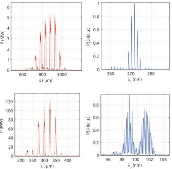
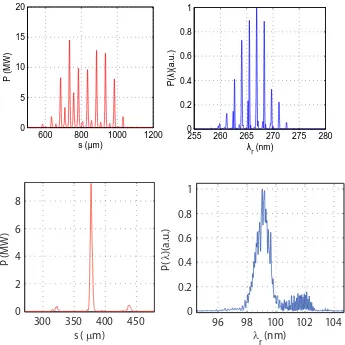
Figure 3.4.100 nm Single Spike SASE Pulses: Power and Spectrum.
values set to match that of the s2e bunch at the position of maximum peak current). The results of the simulations for these two electron bunches are shown in figure 3.2. The left hand plot shows the evolution of power along the undulator lattice for the s2e and gaussian bunches, and the right hand plot shows the photon pulse longitudinal profiles for the s2e bunch after 7 undulator modules. It is seen that both the s2e bunch and gaussian bunch reach FEL saturation before the end of the 7th undulator module at a distance of 16.5 m from the start of the radiator section. These results demonstrate that the electron bunch properties and undulator lattice design are sufficiently good. Many of the FEL schemes to be studied on CLARA will reach saturation earlier in the radiator section, either because they will be tested at longer wavelengths where the gain length is shorter, or because the electron bunch will enter the radiator pre-bunched due to manipulations in the modulator section and chicane.
3.5.2 Generation of short pulses
The generation of short pulses is one of the important research themes for CLARA. Our aim is to generate pulses with as few optical cycles as possible with durations of the order of, or shorter than, the FEL cooperation lengthlc. The cooperation length is the slippage in a gain length and
therefore an intrinsic scale length for the FEL process. It is therefore difficult to generate high intensity FEL pulses of duration less thanlc. The SASE process generates spikes of duration'πlc
with each SASE spike developing independently from the shot noise in the electron beam. Many of the short pulse schemes aim to slice out, or isolate, a single SASE spike and the duration of the output pulse is therefore typically no shorter thanπlc. One gain length in a FEL is typically
one hundred undulator periods, so the cooperation length is therefore typically 100 wavelengths and pulse durations possible from slicing schemes are of this order. In the first two parts of this section we discuss two schemes with this level of potential: Slicing and Single-Spike SASE. To generate shorter pulses than 'πlc requires fundamentally altering the FEL process. Two such
2014 JINST 9 T05001
Slicing schemes
One promising scheme for ultra-short pulse generation is the energy chirp plus tapered undulator scheme [13] and we have studied the implementation on CLARA in some detail [45] following earlier assessment for implementation on the UK’s NLS proposal [46]. In this scheme, a few-cycle seed laser is used to modulate the electron beam energy to an amplitude greater than the natural bandwidth of the FEL. By tapering the gap of the undulator, only the sections of the electron bunch where the energy chirp is correctly matched to the undulator taper will experience high FEL gain. The final FEL pulse therefore consists of a train of individual SASE spikes, each separated by the seed laser period. The number of spikes can be controlled by varying the number of cycles in the seed laser and periods in the modulator undulator — by using a single-cycle laser and a single period modulator a solitary spike can be generated which would be the ultimate aim for implementing this scheme at short wavelengths.
For CLARA it is not feasible to provide a single cycle seed of appropriately long wavelength and pulse energy but we can demonstrate the physics of the mechanism by generating a train of spikes. The scheme has been studied using a combination of elegant [47] andGENESIS 1.3 assuming Gaussian electron bunch distributions with parameters as given in table3.1.
Simulations were carried out for both 400 nm and 266 nm FEL wavelengths. For the 400 nm case, a seed laser of 50µm wavelength looks optimal, with a 500 fs/10µJ pulse providing suffi-cient energy modulation to restrict the growth of the SASE radiation spikes to the energy-chirped regions. For the 266 nm case, a similar seed laser pulse energy would be required, but the wave-length should be reduced to 40µm in order to give a good match between the length of the energy chirps in the electron bunch and the width of the SASE radiation spike ('πlc). Assuming these
conditions can be met, numerical simulations suggest FEL pulses of the order 50 MW peak power and 50 fs/15µm/55 cycles FWHM can be expected.
Figure 3.3 shows the calculated energy modulation given to the electron bunch, along with the FEL pulse profile at saturation for 10 different shot-noise seeds. The taper in radiator gap was applied in steps, with constant gap for each undulator module.
The EEHG scheme discussed later can also be used to control the length of the FEL pulse by varying the length of the second seed laser, keeping the electron energy modulation amplitude fixed. Studies of this option using a 40 fs FWHM laser indicate the scheme will work just as well as when using the 500 fs seed, generating a temporally coherent FEL pulse of >100 MW peak power and 25-40 fs FWHM duration at 100 nm.
Single spike SASE
The idea of the single-spike SASE scheme is simple. In a SASE FEL the spacing between the SASE spikes is∆s≤2πlc. If the electron bunchLb>2πlc then the number of SASE spikesNin
the FEL output will beN=Lb/2πlc[48]. If however the electron bunch is of lengthLb'2πlcthen
only one SASE spike can develop, hence the term single-spike SASE. For Lb<2πlc then again
only one SASE spike will develop, but the saturation power will be reduced because the radiation will slip out of the front of the electron bunch before it can be fully amplified.
2014 JINST 9 T05001
600 800 10000 1 2 3 4 5 6
s (µm)
P (MW)
260 270 280 0
0.2 0.4 0.6 0.8 1
P(
λ
)(a.u.)
λr (nm)
200 250 300 350 400 0
20 40 60 80 100 120
s (µm)
P
(MW)
96 98 100 102 104 0
0.2 0.4 0.6 0.8
P(
λ
)(a.u.)
[image:25.595.116.463.89.429.2]λr (nm)
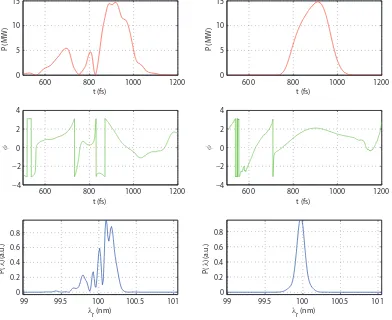
Figure 3.5. Mode-locked output pulses and spectra using the standard CLARA configuration, at 266 nm (top) and 100 nm (bottom).
Mode-Locking
2014 JINST 9 T05001
600 800 1000 1200
0 5 10 15 20
s (µm)
P (MW)
255 260 265 270 275 280
0 0.2 0.4 0.6 0.8 1
P(
λ
)(a.u.)
λr (nm)
300 350 400 450
0 2 4 6 8
s (µm)
P
(MW)
96 98 100 102 104
0 0.2 0.4 0.6 0.8 1
P(
λ
)(a.u.)
λr (nm)
Figure 3.6. Mode-locked output pulses in the second phase of the research. Output at 266 nm with
ex-tra delays within standard undulators (top) and single-spike mode-locked output at 100 nm with 120µm
modulation (bottom).
0 20 40 60 80 100 120 140 160 180 200 0
5 10 15 20
t [fs]
P [MW]
90 100 110 0
2 4x 10
4
λ [nm]
P(
λ
) [a.u.]
[image:26.595.125.470.90.435.2]3
Figure 3.7.Simulation results of the Mode-Locked Afterburner operating at 100 nm.
2014 JINST 9 T05001
the output spectrally. We would then reduce the wavelength to 100 nm and rely on the spectraldiagnostics only, looking for equivalent spectral profiles at 266 nm and 100 nm to prove the scheme. The simulation results at 266 nm and 100 nm are shown in figure3.5. A 50µm energy modulation
has been added to the beam, and the delays are set so that total slippage in undulator module and delay is also 50 µm. The results indicate that in this phase the scheme can be proven in
principle. For the results shown here, the FWHM pulse lengths (of individual pulses within the train) are 43 fs/13µm/50 cycles at 266 nm and 18 fs/5µm/50 cycles at 100 nm. For comparison πlc '20µm at 266 nm and πlc '10µm at 100 nm. The spectra show that the output is also
discretely multichromatic over a full 7% bandwidth which is far broader than the SASE bandwidth. In the second phase the aim would be to reduce pulse durations further to below the FEL cooperation length, using additional delays which would be inserted within the undulator modules — from the scalings given in [15] this would enable a broader gain bandwidth supporting more modes and thus the synthesis of even shorter pulses within the train. Simulation results of this setup, operating at 266 nm, are shown in figure3.6. The pulse length obtained is 17 fs/5µm/20
cycles, more than a factor of two shorter than possible with the standard configuration.
Another interesting possibility, also shown in figure3.6, is an extension scheme where it might be possible to generate isolated pulses. The modulation wavelength is longer here, at 120µm. The
motivation for this is by obtaining the correct ratio between electron bunch length and modulation period it is possible to preferentially amplify only a single pulse within the train. The pulse duration obtained here is 14 fs/4µm/40 cycles. Further study is required of this concept but the hope is to
eventually demonstrate the production of isolated mode-locked pulses. It may in fact be possible to do this with a 50µm beam modulation if the electron bunch is compressed to the appropriate
length.
Mode-Locked Afterburner
The Mode-Locked Afterburner scheme [16] is a development of the mode-locked amplifier FEL concept and promises to deliver ultra-short pulses. It retains the baseline radiator stage of the CLARA FEL, with short pulses generated in a relatively short ‘afterburner’ comprising several few-period undulators separated by chicanes. For CLARA the electron bunch would be modulated with period 3 µm using an Optical Parametric Amplifier (OPA) driven by the Ti:sapphire laser.
Simulation results using GENESIS 1.3 are shown in figure 3.7 using the following afterburner parameters: each undulator module has 8 periods and the chicanes comprise four 2.9 cm length, 0.25 T dipoles. FWHM pulse durations of 1.6 fs/0.5µm/5 cycles are predicted, with peak power
reaching'20 MW in 10 undulator-chicane modules, so the total afterburner length is just over 4 m. The spectrum shows clearly separated distinct wavelengths, over a broad bandwidth of∼13%.
Summary of pulse durations
For each scheme in this section the predicted pulse durations are summarised in table3.2in units of fs,µm, number of optical cycles and number of cooperation lengths. For reference the cooperation length lc '7 µm at 266 nm andlc '3µm at 100 nm. It is seen that the Slicing/Taper, EEHG
2014 JINST 9 T05001
shorter (but in a train) of around 50 cycles or just less than 2 cooperation lengths. With theMode-Locking scheme upgraded in Phase II pulses would come down to around 20 cycles (in the train) or less than one cooperation length, or for the case where an isolated pulse could be produced about double this number of cycles. Finally, the Mode-Locked Afterburner may produce pulses of only 5 cycles, nearly an order of magnitude less than the cooperation length.
Table 3.2.Predicted pulse durations for CLARA Short Pulse Schemes.
FWHM Pulse Duration
Scheme Pulse Type Wavelength (nm) fs µm #cycles #lc
Slice/Taper Single 266 50 15 56 2.2
EEHG Single 100 25 8 75 2.6
Single-Spike SASE Single 100 23 7 70 2.3
Mode-Locking Phase I Train 266 43 13 49 1.9
Train 100 18 5.3 50 1.8
Mode-Locking Phase II Train 266 17 5.1 20 0.7
Single 100 14 4.1 41 1.4
Mode-Locked Afterburner Train 100 1.6 0.5 5 0.16
3.5.3 Improving temporal coherence
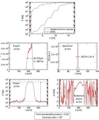
Currently the full potential of X-ray FELs is not realised because they operate in SASE mode for which the temporal coherence is relatively poor. For this reason, their spectral brightness is typically two orders of magnitude lower than that that of a transform limited source. Improvement of SASE FEL temporal coherence would greatly enhance scientific reach and allow access to new experimental regimes. There are a number of methods for improving SASE coherence, many of which have been tested or are already in routine use. Existing methods fall into two classes. In the first class, an externally injected seed source of good temporal coherence ‘seeds’ the FEL interaction so that noise effects are reduced. This seed field may be either at the resonant radiation wavelength, where available, or at a subharmonic which is then up-converted within the FEL. These methods, which include HGHG [51–54] and EEHG [43,44], rely on a synchronised external seed at the appropriate wavelength, pulse energy and repetition rate. In the second class, the coherence is created by optical manipulation of the FEL radiation itself, for example by spectrally filtering the SASE emission at an early stage for subsequent re-amplification to saturation in a self-seeding method [55–58], or via the use of an optical cavity [33–40]. Methods in this class rely on potentially complex material-dependent optical systems which limit the ease and range of wavelength tuning. If an optical cavity is used, the electron source repetition rate should also be in the MHz regime to enable a practical cavity length. A third, more recently proposed class of methods, rely on artificially increasing the slippage between FEL radiation and electron bunch to slow down the electrons which extends the coherence length [59–61] or even completely ‘delocalises’ the FEL interaction allowing the radiation coherence length to grow exponentially [62].
2014 JINST 9 T05001
Figure 3.8. Simulation results for the seeded harmonic cascade scheme, showing peak power along the radiator compared to an equivalent SASE case (top), and the pulse properties at saturation (bottom).
Seeded harmonic cascade
When using injected seed sources to improve FEL temporal coherence, an important aspect is to extend the seeding effect beyond the wavelength range of available seed sources towards the much shorter wavelengths achievable with FELs. Methods to do this involve operating the FEL in stages, with harmonic up-conversion to shorter wavelength at each stage. The use of multiple such stages is termed a ‘seeded harmonic cascade’, and is a key underlying technique of the recently commissioned FERMI@Elettra facility [6] and also for the proposed UK NLS project [42,63].
2014 JINST 9 T05001
0 50 100 150 200
0 0.05 0.1 0.15 0.2 0.25 0.3
time (fs)
initial b
unching
0 50 100 150 200
0 100 200 300 400
time (fs)
power at saturation (MW)
97 98 99 100 101 102 103
0 1 2 3 4 5x 10
11
wavelength (nm)
p
ower at sa
turati
o
n (arb.
uni
ts)
0 50 100 150 200
−3 −2 −1 0 1 2 3
time (fs)
p
h
a
se at satur
a
ti
o
n (r
a
d
)
SASE (0m) EEHG (0m)
SASE (13.5m) EEHG (6.5m)
SASE (13.5m) EEHG (6.5m)
[image:30.595.131.453.88.320.2]SASE (13.5m) EEHG (6.5m)
Figure 3.9.EEHG: comparing the final FEL pulse to a standard SASE simulation, the FEL pulse generated using EEHG shows a more uniform peak power at saturation, reduced bandwidth and constant radiation phase, combined with a substantial reduction in saturation length.
100 nm FEL operation. The seed imprints a sinusoidal energy modulation on the electron beam within the modulator undulator, then chicanes convert this into a density modulation (or ‘bunching’) containing higher harmonic components. The induced energy spread must be sufficiently low to allow FEL lasing in the final stage.
A two stage harmonic cascade could be demonstrated with the baseline CLARA layout by using the first radiator undulator as a modulator. GENESIS 1.3simulations were carried out and the results are shown in figure 3.8. An 800 nm seed with 200 fs FWHM duration and 0.5 MW peak power was used in the modulator to apply an energy modulation∆γ/σγ≈1. The chicane was
set forR56≈200µm, giving a bunching factor of∼2% at 400 nm. This is deliberately less than
optimum — the first radiator stage used as a modulator resonant at 400 nm is relatively long, so the relatively low bunching factor acts to keep the induced energy spread sufficiently low in this stage. Energy modulation of ∆γ/σγ ≈6 was applied, giving∼20% bunching factor at 100 nm, using
the inter-module electron delay chicanes to apply a relatively low compression (R56≈60 µm).
The remainder of the radiator is resonant at 100 nm and the FEL saturates after only two undulator modules with excellent temporal coherence and contrast ratio over the SASE background, as shown in figure3.8.
2014 JINST 9 T05001
600 800 1000 1200
0 5 10 15
t (fs)
P (MW)
600 800 1000 1200
−4 −2 0 2 4
φ
t (fs)
99 99.5 100 100.5 101
0 0.2 0.4 0.6 0.8
P(
λ
)(a.
u
.)
λ r (nm)
600 800 1000 1200
0 5 10 15
t (fs)
P (MW)
600 800 1000 1200
−4 −2 0 2 4
φ
t (fs)
99 99.5 100 100.5 101
0 0.2 0.4 0.6 0.8
P(
λ
)(a.
u
.)
[image:31.595.98.490.111.431.2]λ r (nm)
Figure 3.10.Results of 100 nm RAFEL simulations. The left hand column shows the control case without an optical cavity, i.e. normal SASE, whereas the right hand column shows the effect of adding the feedback — the output pulse is cleaned up both spectrally and temporally. The pulse is shown after 11 cavity round trips.
Echo-enabled harmonic generation
The EEHG scheme has been proposed as a way to improve the temporal coherence of FEL pulses, and works by combining two energy modulation stages with two chicanes to induce a fine-structure density modulation in the electron bunch [43]. The electron bunch is then sent through a radiator section resonant at the density modulation wavelength, ultimately generating a temporally coherent FEL pulse at a wavelength many times shorter than the initial seed lasers. Initial studies of this scheme [68] assumed both modulators were identical, with 65 mm period and 1 m total length but for implementation on CLARA the first radiator would be replaced by an additional short modulator and weak chicane. We expect performance to be similar in this configuration.
2014 JINST 9 T05001
achieved using seed lasers of up to 100 µJ pulse energy with 500 fs rms pulse duration. Themaximum requirements placed on the two chicanes would beR56 values of 41 mm and 0.5 mm respectively.
To complement the analytical studies, numerical simulations have been carried out atλFEL =
100nm (8th harmonic) usingelegantfor the two modulator and chicane sections, andGENESIS 1.3for the radiator section. The tracking inelegantwas carried out with and without coherent and incoherent synchrotron radiation emission in the chicane dipoles. In the simulations, a 250 fs long section of the electron bunch was studied, with sufficient particles to account for the indi-vidual electrons (>590M particles). The seed laser pulse energy was 10µJ. Comparing the final
FEL pulse to a standard SASE simulation, the FEL pulse generated using EEHG shows a more uniform peak power at saturation, reduced bandwidth and constant radiation phase, combined with a substantial reduction in saturation length, as shown in figure3.9.
For the study of coherent bunching at very high harmonics, i.e. at wavelengths shorter than 100 nm where it will not be possible to demonstrate lasing, methods for generating coherently enhanced radiation from the electron beam may be used as a diagnostic. This is a subject for further study.
RAFEL
Simulations have been done of a RAFEL driven by CLARA operating in multibunch mode, with electron bunch parameters given in table3.1. The one-dimensional FEL oscillator simulation code FELO [69] was employed. Although this code does not model the radiation propagation in the cavity, employing instead a simple radiation feedback factor, its predictions of the longitudinal radiation characteristics and build up from shot noise have been shown previously to agree well with fully three-dimensional simulations of RAFEL systems using GENESIS 1.3and dedicated optical propagation codes [70].
Only five of the seven radiator undulators are required. The radiation feedback factor F to maximise the output power and longitudinal coherence [38] is given byF=25 exp(−√3G)where
G=4π ρNw with ρ the usual FEL parameter and Nw the number of undulator periods. For the
electron bunch parameters as listed in table3.1it is found thatF=1.8×10⁻³showing that only a very small fraction of the emitted radiation needs to be fed back via the optical cavity to the start of the undulator. The scheme is in effect a self-seeded FEL rather than an oscillator FEL because there is no requirement to build up a stable optical mode in the resonator.
The simulation results are shown in figure3.10where the RAFEL has reached saturation after 11 cavity round trips. The left hand plot shows the control case for these parameters without an optical cavity, i.e. normal SASE, whereas the right hand plot shows the effect of adding the feedback — the output pulse is cleaned up both spectrally and temporally with time bandwidth product(∆λ/λ2)c∆t=0.58 which is close to that of a transform limited pulse. Simulations for 266 nm and 400 nm output also show near transform limited output using optimum feedback factors ofF=4.5×10⁻⁶andF=3.5×10⁻⁷respectively.
2014 JINST 9 T05001
Figure 3.11.HB-SASE: the spectra (in scaled frequency ¯ω= (λ−λr)/2ρ λr) of four statistically indepen-dent 100 nm SASE pulses on the top row, and the spectra of four statistically indepenindepen-dent HB-SASE pulses on the bottom row.
High-brightness SASE schemes
A recently proposed class of methods rely on artificially increasing the slippage between FEL ra-diation and electron bunch to enhance the SASE FEL longitudinal coherence and hence improve the spectral brightness. This can be done by using chicanes to apply a series of unequal delays to the electron bunch as it propagates though the undulator [59]. Variations of the scheme have been studied in some detail and named High-Brightness SASE (HB-SASE) [62] and Improved SASE (iSASE) [72]. For CLARA the delays can be applied via magnetic chicanes between un-dulator sections, using the same hardware as required for the Mode-Locking scheme discussed in section3.5.2. A proof-of-principle experiment to demonstrate the concept has already been done successfully at the LCLS using detuned undulator sections as delays, but this only allowed a limited slippage enhancement [73]. Another proposal called purified SASE (p-SASE) [61] suggests using subharmonic undulators as ‘slippage-boosted’ sections. Theoretical work on HB-SASE and iSASE has shown that by using magnetic chicanes to delay the beam and optimising the delay sequence it may be possible to significantly extend the radiation coherence length. Further advantages are that the efficiency of a taper can be much enhanced and that the shot-to-shot stability of the out-put power in the presence of electron beam energy fluctuation should be improved compared to a self-seeding scheme using optics [60].
2014 JINST 9 T05001
3.5.4 Afterburner schemes
A number of schemes which use afterburner undulators could be tested:
Short wavelength generation. This is done by exploiting the electron beam bunching at har-monics which are higher than the FEL resonance. This harmonic bunching occurs naturally within the beam due to the FEL interaction. By propagating the beam into a short afterburner which is tuned to this harmonic the beam can be made to emit a pulse of coherently enhanced radiation at a wavelength shorter than the FEL wavelength. This burst of radiation undergoes a sharp initial power growth (quadratic with distance through the afterburner) which rapidly saturates — the en-ergy spread induced in the beam by the previous FEL interaction prohibits exponential growth and lasing, but the emitted power can still be orders of magnitude greater than incoherent spontaneous undulator emission. Such afterburner schemes are of interest to many FEL facilities as a way of extracting useful short wavelength radiation from an otherwise ‘spent’ beam. The research interest is in the use of compact novel undulators for this purpose.
Exotic short pulse generation. A proof of principle experiment could be done for the ‘mode-locked’ afterburner concept, which is a new proposal for generating FEL pulses in the zeptosecond regime from existing X-ray FELs via a compact afterburner extension. This idea was explained further in section3.5.2.
Polarisation control. To generate circularly polarised radiation via the crossed undulator scheme. This requires two undulators as the final FEL radiators with orthogonal linear polarisation [77]. Al-ternatively a single variably polarised undulator could be used as the final radiator to demonstrate high intensity variably polarised emission from an electron beam strongly bunched in the pre-vious planar undulators [63].
3.6 Scaling to short wavelengths
The CLARA wavelength range, in the visible and VUV, has been chosen to enable easy diagnosis of the output. For many schemes we are concerned only with the underlying physics of the mecha-nism which is often wavelength-independent — the wavelength only becomes an issue when con-sidering those factors specific to the scheme in question which may mitigate performance at shorter wavelengths. However, scalability to shorter wavelengths is important to understand because the R&D done at CLARA will be applied at FELs which operate at shorter wavelengths than CLARA can access. This will benefit UK scientists whether they are current users of short-wavelength FEL facilities abroad or future users of a short-wavelength FEL facility in the UK.
2014 JINST 9 T05001
For example, in many schemes one or more magnetic chicanes are used, either tolongitudi-nally shear the electron bunch or delay it with respect to the radiation. Often some wavelength-specific tolerances on the stability of these chicanes have been determined in the original papers (see for example [15]). Sometimes more specific issues have been raised which need further study, such as: the effect ofR51leakage smearing the imparted modulation in EEHG; the degrading ef-fect of Coherent Synchrotron Radiation (CSR) emission in the chicanes; the washing out of FEL induced microbunching during beam transport; the discrepancy between the EEHG model, which assumes each harmonic has a δ-function linewidth, and reality where the harmonics all have a
width which depends on laser pulse length, chirp, laser phase noise and electron beam shot noise. All of these effects will become relatively more significant for the finer beam manipulations and structures required at shorter wavelengths. Using CLARA we will be uniquely placed to actively study the impact of these effects by progressively changing the input parameters and carefully as-sessing the FEL performance. For example we can add errors to magnet angles, add jitter to mag-net power supplies, adjust the laser heater settings to control the beam microbunching, propagate bunched beams over variable distances before diagnosing the bunching degradation via Coherent Optical Transmission Radiation (COTR) screens, adjust the laser chirp and pulse duration, and so on. In this way we can obtain invaluable data which can be used to prioritise schemes for future implementation at X-ray wavelengths.
As a last comment, we consider how the pulse durations for the CLARA short pulse schemes would scale if implemented on an X-ray FEL. For the Slice/Taper scheme and the Single Spike SASE scheme the pulse duration would be expected to scale with the cooperation timetc=lc/c. An
estimate fortcat 0.15 nm wavelength istc'80 as, so from table3.2which gives the pulses lengths
2014 JINST 9 T05001
Chapter 4
Accelerator design
4.1 Layout overview
Figure 4.1.CLARA layout overview.
The design approach for CLARA is to build in flexibility of operation, enabling a wide ex-ploration of FEL schemes. To this end a range of possible accelerator configurations have been considered. A major aim is to test seeded FEL schemes. This places a stringent requirement on the longitudinal properties of the electron bunches, namely that the slice parameters should be nearly constant for a large proportion of the bunch length. In addition, CLARA should deliver high peak current bunches for SASE operation and ultra-short pulse generation schemes, such as ve-locity compressed bunches. This flexibility of delivering tailored pulse profiles will allow a direct comparison of FEL schemes in one facility.
2014 JINST 9 T05001
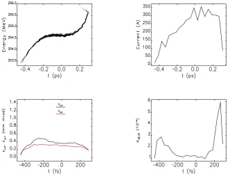
Figure 4.2.(1) Laminarity (black/red) in the 10% of charge slice containing the peak current with sion at 70 MeV/130 MeV (for an indicative layout). (2) Longitudinal phase space (black/red) with compres-sion at 70 MeV/130 MeV.
A fourth harmonic linearising X-band cavity (11994 MHz) [79] is situated before the mag-netic compressor to correct for longitudinal phase space curvature. A variable magmag-netic bunch compressor is then followed by the first dedicated beam diagnostics section, incorporating trans-verse deflecting cavity and spectrometer, enabling measurement of emittance, bunch length and slice properties. Linacs 3 & 4 (each∼4 m long) accelerate to 250 MeV. These are followed by a second diagnostics section. It has also been proposed to divert this high energy beam for other applications. The beamline then passes a dogleg, offsetting the FELs from the linacs transversely by∼50 mm to enable co-propagation of long wavelength laser seeds. Immediately following the dogleg is the FEL modulator undulator and chicane. A dedicated matching section ensures that periodic optics is achievable in the radiators for the entire wavelength range. Seven FEL radiators and a space for a FEL afterburner complete the accelerator and the beam is then dumped.
4.1.1 Phase space linearisation
Magnetic compression of electron bunches requires that some attention be given to the removal of the curvature imposed on the longitudinal phase space of the bunch by the accelerating RF. For CLARA, a harmonic linearising cavity was compared with non-linear magnetic correction in the chicane [80]. The additional complication of a harmonic cavity was shown to be justified by the ability to predictably tailor the longitudinal phase space.
4.1.2 Energy at magnetic compressor
2014 JINST 9 T05001
Table 4.1.Specification of variable bunch compressor.
Value Unit
Energy at compressor 70 - 150 MeV Min. : Max. bend 0 : 200 mrad Bend magnetic length 200 mm
Max. bend field 0.5 T
Min. : Max. offset 0 : 300 mm Separation of dipoles 1 & 2 1500 mm Separation of dipoles 2 & 3 1000 mm Max. bellows extension 260 mm Min. : Max.R56 0 : -72 mm
Beam size fromδE (±6σ) 0 : 20 mm
Beam size fromβx(±6σ) 3.0 mm
space-charge effects. T