2017 2nd International Conference on Information Technology and Industrial Automation (ICITIA 2017) ISBN: 978-1-60595-469-1
Method of Controlling Movement of the
Multi-Degrees of Industrial Robot’s Joint
Eryou West
ABSTRACT
Multi-degrees industrial robot has many joints; every joint is controlled by a servo motor. In order to let mechanical hand of a robot move from one point to another, every joint must move in special method. It elaborates a method of controlling robot’s joints starting and stopping at the same time. Programmed in motion controller with this method, not only can realize starting and stopping at same time of every joint of robot, but also adjust the moving speed of every joint of the robot, finally, let the robot of using the technology suitable in various production applications.
INTRODUCTION
Robot technology is a technology which combined with computer technology and automation technology. After more than half century of development, the robot technology has widely used in industrial production field, it greatly improved the production quality and liberated the man labor. As a high technology in one of the cutting-edge technology, robotic technology has the important role for academic research, industrial upgrading, cultivating creative consciousness, safeguarding national security and leading the future economic and development. At present, the breakthrough of some relevant technology, provide support for the academic
________________________
research of robot technology and broadens the scope of application of industrial robot.
FOREIGN INDUSTRIAL ROBOT DEVELOPMENT HISTORY AND CURRENT SITUATION
The first commercially produced robot was developed in 1959. In 1962, the first industrial robot to be used on a production line was installed by GM. A major step forward in robot control occurred in 1973 with the development of the T-3 industrial robot by Cincinnati Milacron.
Through a variety of automation techniques, including robots, Japanese manufactures, beginning in the 1970s, were able to produce better automobiles more cheaply than U.S manufactures. Consequently, in order to survive, U.S manufacturers were forced to consider any technological development that could help improve productivity. It became imperative to produce better products at lower costs in order to be competitive with foreign manufactures. Other factors such as the need to find better ways of performing dangerous manufacturing tasks contributed to the development of industrial robots. However, the principal rationale has always been, and it still, improved productivity.
THE STRUCTURE AND PARAMETER OF A ROOT
An Industrial Robot Structure
An industrial robot includes parts describe as follows:
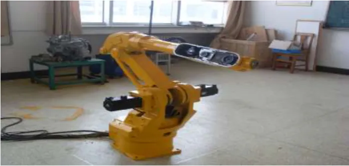
THE MAIN BODY OF THE ROBOT
Figure 1. Six degree industrial robot.
ENDING EXECUTOR
Manipulator is fixed at a robot’s last joint; it acts on the task parts and is the all appellation of the robot’s hand part, grasp framework, paw and tools fixed on the ending arm. Usually, the movement of the ending executor is controlled by the robot’s controller.
DRIVER
Driver is a manipulator’s “muscle”. At present, a manipulator’s driving way include air driving, hydraulic pressure driving and servo motor. Servo motor driving has the advantage of using conveniently and easily control. Consequently, servo motor is widely used by industrial robot.
SENSOR
Sensor is used for collect information coming from the inner and outer of the robot. Inner state sensor is used for check the position of every joints and their moving speed; Outer state sensor is used for check some state variables involved with robot and its surroundings, such as distance, approaching degree, etc. The purpose of using sensor is to guide the robot to make necessary reaction3.
CONTROLLER
SOFTWARE
The software used for robot includes three parts: the first part is operation system which is used for operating computer, the second part is robot software, it computes according to robot’s moving equation and then guides every joints’ movement. at last, transfers all the information to controller; the third part is the software developed for some outer equipment. The software developed for the robot mentioned in this paper is programmed using Otostudio.
INDUSTRIAL ROBOT TECHNICAL PARAMETER
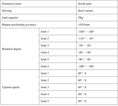
[image:4.612.101.492.324.676.2]Every joints of an industrial robot should rotate independently, but has some limitation, some joints’ rotation degree is big, some small. A very important index is the motion repeat accuracy and this index is guaranteed by mechanical and electrical controlling system2.
TABLE I. 6 DEGREE INDUSTRIAL ROBOT’S TECHNICAL PARAMETER.
Framewor form Serial joint
Driving Servo motor
load capacity 5Kg
Repeat positioning accuracy ±0.01mm
Rotation degree
Joint 1 -160°~ 160°
Joint 2 -135°~ -45°
Joint 3 -70°~ 50°
Joint 4 -90°~ 90°
Joint 5 -90°~ 90°
Joint 6 -180°~ 180°
Upmost speed
Joint 1 60° / S
Joint 2 60° / S
Joint 3 60° / S
Joint 4 60° / S
Joint 6 120° / S
height 820 mm
weight 50Kg
Operating way Teaching/playback
INTRODUCTION OF THE CONTROLLER
The CPAC programmable develop platform produced by Googoltech company is based on Goolgoltech’s GUC800 8 axis motion controller. It’s a programming software called OtoStudio. OtoStudio is combined with the function of program developing, program debugging and program demonstrating. It also meet the standard of IEC61131-3, PC standard ( JB/T 8384-1996 ) and PLC standard (GB/T 15969.2-1995), it has passed many tests by EMC, it also pass the authentication of CE. It has the advantage of real time motion controlling, I/O control function, prolific human-machine interface programmable, etc.
INTRODUCTION OF THE CONTROLLING METHOD
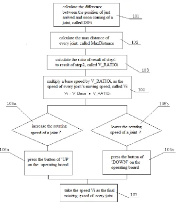
Figure 2. Controlling flow chart.
Show in fig. 2, the method of controlling multi degree industrial robot’s servo motor speed are described as follows steps:
Step1:calculate the difference between the position of just arrived and soon coming of a joint, called DIFi, If a joint’s movement is beginning, DIFi is equal to the soon coming coordinate.
Step2:calculate the max distance of every joint, called MaxDistance.
Step5:if want to increase the rotating speed of a joint, press the button of ‘UP’ on the operating board; if want to lower the rotating speed of a joint, press the button of ‘DOWN’ .
Step6:take the speed Vi as the final rotating speed of every joint.
CONCLUSIONS
In the study of robotics, the complex motion of multi-degree robot has important research value and practical significance. The method mentioned in this paper is programmed using googol motion controller. By running the program, realized not only the motion way of starting and stopping at the same time but also the motion speed adjust freely, increased productivity. After long time running, it proved the method is reliable. A invention pattern based on this method has been applied.
REFERENCES
1. Cai Z X. Developing trends of robot technology in 21st century[J]. Journal of Nanjing University of Chemical Technology, 2000, 22(4): 73-78.
2. Wei H X, Chen Y D, Tan J D, et al: Sambot: A self-assembly modular robot system[J]. IEEE/ASME Transactions on Mechatronics, 2011, 16(4): 745-757.
3. Siegwant R, Nourbakhsh I R. Introduction to autonomous mobile robots [M]. Massachusetts, MA, USA: MIT Press, 2004.