2017 2nd International Conference on Software, Multimedia and Communication Engineering (SMCE 2017) ISBN: 978-1-60595-458-5
Analysis and Verification of Core Factors in
Radio Wave Propagation Loss
Na ZHENG
The State Radio Monitoring Center, Beijing, 100037
Keywords: Radio wave propagation, Field strength coverage, Electromagnetic compatibility analysis, Propagation model.
Abstract. Radio wave propagation prediction can calculate the radio frequency link parameters such as field strength coverage and reception of power, which is an important foundation of electromagnetic compatibility (EMC) analysis and frequency coordination. This paper reviews the advances in the research of radio wave propagation by the International Telecommunication Union (ITU) and the International Radio Science Consortium (USRI), analyzes the core influencing factors related to the propagation of radio waves, including the propagation environment and the propagation model used in the calculation which EMC analysis system has been verified. The related content can provide reference for electromagnetic compatibility analysis and the border coordination.
Introduction
The electromagnetic environment in the border area is becoming more and more complicated, and the radio service has been widely used in communication, broadcasting, national defence, transportation, aviation, fishery and other industry sectors. However, due to the characteristics of radio wave propagation are not subject to administrative regions, national boundaries, signal transitions or radio interference phenomenon is very common[1]. There are various effects on the propagation path of the signal, such as the effects of high-altitude ionosphere, the influence of mountains, lakes, oceans, ground buildings, vegetation and the Earth's surface[2]. These factors are the key parameters to estimate the radio propagation loss, affecting the communication distance of the radio system and the range of radio interference, and it is necessary to carry out the relevant research. With the International Telecommunication Union (ITU), the International Radio Science Union (USRI) and other research institutions in the field of radio wave exploration, radio wave research has developed by considerable development. This paper analyzes the research status and progress of ITU-R Study Group 3 (SG3) and USRI in the field of radio wave propagation, and also includes the observation and research of radio wave environment in China Radio Wave Propagation Institute. Secondly, from the propagation environment (geographical climate and terrain). Finally, the electromagnetic compatibility (EMC) analysis system is used to simulate the loss of radio wave propagation in different terrain and different propagation modes. Finally, the electromagnetic interference (EMC) analysis system is used to analyze the influence of radiation propagation on different transmission modes, which verifies the influencing factors of the wave propagation loss and provides a scientific and accurate basis for the border coordination to determine the coverage of the radio station.
Research on Radio Propagation in International and Domestic Organizations
speed[7]; and secondly the radio wave propagation prediction method[8], generally have been revised by a few or even a dozen versions , the specific content is in Table 2.
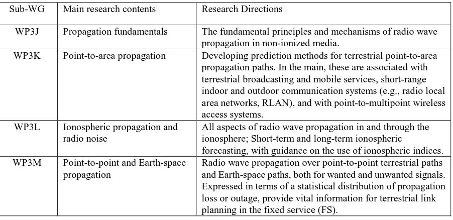
Table 1. Introduction of ITU-R SG3.
Sub-WG Main research contents Research Directions
WP3J Propagation fundamentals The fundamental principles and mechanisms of radio wave propagation in non-ionized media.
WP3K Point-to-area propagation Developing prediction methods for terrestrial point-to-area propagation paths. In the main, these are associated with terrestrial broadcasting and mobile services, short-range indoor and outdoor communication systems (e.g., radio local area networks, RLAN), and with point-to-multipoint wireless access systems.
WP3L Ionospheric propagation and radio noise
All aspects of radio wave propagation in and through the ionosphere; Short-term and long-term ionospheric
forecasting, with guidance on the use of ionospheric indices. WP3M Point-to-point and Earth-space
propagation
[image:2.595.75.526.122.341.2]Radio wave propagation over point-to-point terrestrial paths and Earth-space paths, both for wanted and unwanted signals. Expressed in terms of a statistical distribution of propagation loss or outage, provide vital information for terrestrial link planning in the fixed service (FS).
Table 2. The radio wave propagation prediction method.
Number Recommendations Research contents Frequency bands
1 P.452-16 Prediction procedure for the evaluation of interference between stations on the surface of the Earth at frequencies above about 0.1 GHz
100MHz-50GHz
2 P.1546-5 Method for point-to-area predictions for terrestrial services in the frequency range 30 MHz to 3 000 MHz
30MHz~3000MHz
3 P.840-6 Attenuation due to clouds and fog Above 10GHz
4 P.530-16 Propagation data and prediction methods required for the design of terrestrial line-of-sight systems
50MHz~100GHz
The International Union of Radio Science (URSI) is one of the scientific organizations directly under the International Council for Science (ICSU). There are 10 committees, which are related to radio communication. The F committee "wave propagation and remote sensing" and G committee "ionospheric radio wave propagation" are related to radio waves[9]. The main research contents of the G Committee include the propagation of planets, neutral earth and surface waves, the interaction of planetary surfaces (land, sea and ice) and sub-surfaces with radio waves, affecting the environmental characteristics of fluctuations. The G Committee studied ionospheric radio and propagation and provided extensive awareness of space and terrestrial radio systems.
Radio wave propagation research is also carried out by agencies such as the Britain Office of Communications (Ofcom), NASA and Rutherford Appleton (RAL)[10].
Core Influencing Factors of Radio Wave Propagation
on the signal level with the estimated propagation model used together, which affect the loss prediction accuracy from transmission antenna to receiving antenna.
The Impact of the Propagation Environment on the Radio Wave Propagation
In the general interference analysis, for a wide range of areas, select the appropriate value for the scene; for special stations, select the station parameters in the database to calculate[11]. In the calculation of radio wave propagation loss, the Earth's equivalent radius, meteorological parameters, radio climates, terrain and surface database, ground cover are factors to consider:
a) Earth equivalent radius
Under vacuum condition, the radio waves travel in a straight line. In the atmosphere, radio waves spread through the gas, the density changes with height. At this time we should consider refraction. In order to facilitate the calculation of engineering[12], considering the impact of atmospheric refraction on the radio wave propagation, in the calculation of path loss, we usually use the equivalent earth radius coefficient K = 4/3 of the standard refraction[13].
b) Geographical climate and meteorological parameters
The influence of complex meteorological changes on the radio wave propagation is relatively large. The research of ITU-R SG3 for geographic climate and meteorological parameters is shown in references[14] [15][16] [17] [18] [19] ,such as water vapour, surface temperature and so on.
c) Radio climates
According to Recommendation ITU-R P.620[20], the world is divided into four basic radio climates, defined as: area A1 is a coastal land and coastal area, area A2 is all land other than coastal land and coastal areas defined in A1, area B is cold sea, ocean and large inland waters (except Mediterranean and Black Sea), area C is warm sea, ocean and large inland waters, as well as the Mediterranean and the Black Sea. The combination of area B and C is simple sea. If necessary, it is referred to the Recommendations in Tab.1 in order to obtain radio climates for specific locations with clear latitude and longitude. Such as the propagation model ITU-R P.452 is applicable to scenes across multiple regions. These area informations can be downloaded from the ITU BRIFIC CD-ROM, such as Digital World Map (IDWM), which has a resolution of 30 radians (approximately 1 km on the equator). NASA engaged in a Synthetic Aperture Radar (SAR) mission in 2000, it can produce higher resolution (3 radian seconds) of the topographic map, also with the height and some cluster data, which is more close to the actual situation.
d) Terrain and surface database
The actual situation of earth model is very complex whether it is spherical or flat sphere, such as hills and valleys, especially buildings and vegetation. There are two types of databases: terrain and surface, to define these features. In estimating the propagation model loss, we must have terrain knowledge. Different types of terrain are: ocean, other water bodies, deserts, dense forests, forests, rural areas, suburbs and urban areas. The surface database includes buildings and vegetation.
e) Classification of ground cover
Due to some limitations of the surface database, it is expensive to extract building height and density by large area modeling, and it requires additional information and models to identify how signal strength is achieved across each pixel. Due to the large extent of the land category, Recommendation ITU-R P.1058 - Terrain Database for Dissemination Studies[21] gives the coding scheme for terrestrial coverage categories.
Effect of Propagation Model on Propagation Loss Estimation
propagation model is based on a defined range (such as frequency, height, percentage of time, etc.) and monitoring, and sometimes including physical concepts and curve fitting. In many applications where spectrum analysis and frequency assignment are required, propagation is simplified to assess the loss.
EMC Analysis System
EMC analysis system includes field strength calculation, interference analysis and other methods, the propagation model covers almost the propagation of ITU Recommendation model, and it make the results of analysis scientific by adding station data and antenna model. In this paper, the typical free space and the ITU-R P.1546 propagation model are analyzed for the proposed 382 MHz cluster station. The station signal coverage area includes mountains, plains and waters areas. In the case of setting the same geographical parameters, signal characteristics, RF antenna system, we select 14161 vector points, which covers up to 13,300 square kilometers to calculate the field strength, comparing the difference between the propagation environment and the propagation model.
(1) Parameters
ITU-R P.1546: 10% Time Probability, 50% Location Probability Equivalent omni-directional radiated power: 32dBW
Latitude and longitude: longitude 122°12'05.62 ", latitude 40°15'58.61" Transmitting antenna height: 50 meters
receiving antenna height: 3 meters (2) Influence factors
We select different propagation models and set different colors to indicate the field strength threshold, field strength is shown in Figure 1,2. In the center circle area of Figure 1, field strength value is between 80-120dBμV/m, the edge value 40dBμV/m. In the center circle area of Figure 2, field strength value is 40dBμV/m, the edge value only 10dBμV/m.
[image:4.595.235.490.452.586.2] [image:4.595.95.279.453.585.2]Figure 1. Field Strength in Free Space. Figure 2. Field Strength in ITU-R P.1546.
In the free space propagation model without terrain factor, the calculation only considers the emission frequency and the propagation distance, which is independent of the terrain and geomorphological factors. Under the ITU-R P.1546 propagation model, there are mountains in the 40°-180° north of the station, the impact of the terrain on field strength is obvious. It can be seen that radio signal propagation is better in the flat area, in the uneven distribution of complex terrain, the field strength attenuate soon. It can be seen that in different propagation patterns, the propagation loss is different, and the radio wave propagation model also includes the influence factors of the environment.
Table 3. Comparison of field strength values.
Vector point topographic map(dBuv/m) geomorphic map(dBuv/m)
1 11.29 11.5
2 11.57 13
3 11.84 13.2
4 12.11 10.1
︙ ︙ ︙
3042 28.72 38.5
︙ ︙ ︙
14160 13.74 12
14161 13.65 10.6
Table 4. Mean and standard deviation of field strength (ITU-R P.1546 ).
Map mean(dBuv/m) standard deviation topographic map 22.15 11.30 geomorphic map 25.70 12.95
In order to further study the effect of geomorphic data on field strength, we plot the distribution of field intensity in the calculation area. As shown in Figure 3, the field intensity difference is characterized by chromaticity bar.
Figure 3. Field strength difference of 382MHz station in the calculation area.
It can be seen that the field strength is affected by the geomorphic features, and the difference in field strength is small in the flat area, larger in the waters (the upper left part of the figure). In the complex terrain with uneven distribution, field strength difference is also larger. The above analysis fully proves the influence of propagation environment and propagation model in estimating the propagation loss of radio waves.
Summary
calculation platform with EMC analysis system, and analyzes the influencing factors qualitatively and quantitatively. This is the basis, designed to effectively support the border coordination.
Acknowledgement
This research was financially supported by the Natural Science Foundation (61139001).
References
[1] Li Pengpeng, Fang Jian, Mang Ge. Frequency Coordination Method of Terrestrial Radio Service in Border area[J].National Conference on Wireless and Mobile Communications[C]. Beijing: the People's Posts and Telecommunications (2014)297-299.
[2] XI Yujiu. Wave propagation mode and the use of each band [J]. Electronic World, (2000). [3] Information on http://www.itu.int/en/ITU-R/study-groups/rsg3/Pages/default.aspx
[4] SUN Gang, WENG Ningquan, XIAO Liming, MA Chengsheng.Structural Constants Distribution and Analysis of Atmospheric Refractive Index in Different Regions [J]. April 2005.
[5] ITU-R Sector. ITU-R Recommendation P.676-10, Attenuation by atmospheric gases [S]. [6] ITU-R Sector. ITU-R Recommendation P.833-8, Attenuation in vegetation [S].
[7] Lin Leke, Zhao Zhenwei, Lu Changsheng, Zhang Xin, LI Na.Several problems in modeling rain attenuation of ground-air path [J] .Chinese Journal of Radio Science, 2016, 31(3).
[8] Information on http://www.itu.int/rec/R-REC-P/en. [9] Information on http://www.ursi.org/en/commissions.asp
[10] Liu Zhimin. Introduction of Rutherford Appleton Laboratory [J]. Radio and Antenna, 1994, 05. [11] John Pahl. Interference Analysis: Modelling Radio Systems for Spectrum Management[M]. Transfinite Systems Ltd, UK.
[12] Xiong Hao, Wang Ailing. Concept and Definition of Equivalent Earth Radius [J]. Journal of Radio Science, March 1997.
[13] SU Jian-feng, LI Xiao-zhen. Discussion on Equivalent Earth Radius Coefficient α in Calculation of Wave Propagation. [J] Journal of Time and Frequency, June 2010.
[14] ITU-R Sector. ITU-R Recommendation P.453-11, The radio refractive index: its formula and refractivity data [S].
[15] ITU-R Sector. ITU-R Recommendation P.835-5, Reference Standard Atmospheres [S].
[16] ITU-R Sector. ITU-R Recommendation P.836-5, Water vapour: surface density and total columnar content [S].
[17] ITU-R Sector. ITU-R Recommendation P.837-6, Characteristics of precipitation for propagation modelling [S].
[18] ITU-R Sector. ITU-R Recommendation P.838-3, Specific attenuation model for rain for use in prediction methods [S].
[19] ITU-R Sector. ITU-R Recommendation P.1510-0, Annual mean surface temperature[S].
[20] ITU-R Sector. ITU-R Recommendation P.620-6, Propagation data required for the evaluation of coordination distances in the frequency range 100 MHz to 105 GHz [S].